Creating Levels, Grids, Layout and model elements for a residential unit using REVIT
Challange-2: Creating Levels, Grids, Layout and model elements for a residential unit using REVIT.
1) What is BIM? Summarize the features of BIM and benefits of using BIM over 2D CAD tools.
ANS: BIM stands for Building Information Modeling and is a workflow process. It's based around models used for the planning, design, construction, and management of building and infrastructure projects. BIM software is used to model and optimize projects by planning, designing, building, and operating BIM models.
BIM is a process in which all the information of the 3D building models is linked and incorporated to produce a comprehensive 3D model. Therefore, Revit is one of the software which supports BIM by creating the data-based model of architectural design, structural design, and MEP design.
Features of BIM:
Building Information Modeling (BIM) is so much more than a technology it’s a complex design and construction process that helps architects create innovative buildings of the future. There are five significant benefits of BIM in the design and construction process:
- Cost and resource savings
- Greater efficiency and shorter project lifecycles
- Improved communications and coordination
- More opportunities for prefabrication and
- modular construction Higher quality results
When you work with an architecture firm that uses BIM during the construction process, your resources may go further. If you want to build a dynamic structure as efficiently as possible, take a closer look at what BIM construction can do.
Advantages of BIM over CAD:
There are multiple advantages working with the BIM methodology some are mentioned below.
- Time saving
- Drastic reduction of Errors
- Simplicity at its best
- Integration with other design aspects
- 3D BIM software
2) Understand the concept of Categories, Families, Elements, Instances in Revit. Go to Insert Tab, choose a category. Pick a family and element. Understand the instances and insert it to Revit model ?
Aim: To Understand the concept of Categories, Families, Elements, Instances in Revit.
Tools Used: Insert toolbar, Load Family.
Procedure:
To load families in the drawing then following procedure is mentioned below.,
- Click Insert tab then Load from Library panel (Load Family).
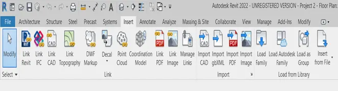
- In the Load Family dialog, double-click the category of the family that you want to load. In this case use us Family.
- Preview any of the families in the category: To preview a single family, select it from the list. At the top right of the dialog, under Preview, a thumbnail image of the family displays.
- To display a thumbnail image in the list for all families in the category, at the top right corner of the dialog, click Views
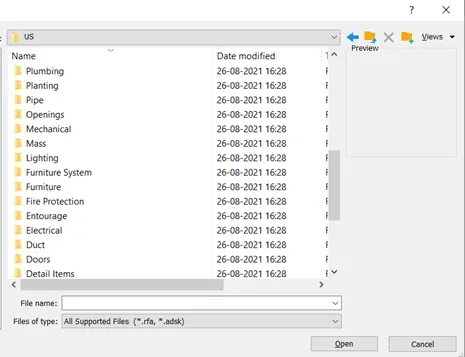
- Select the family that you want to load, and click Open.
- The family type is now available to place in the project. It displays in the appropriate category under Families in the Project Browser.
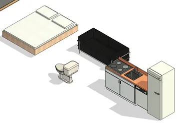
Result: Different Categories, Families, Elements, Instances in Revit is Discussed and images are attached.
3) Setting up a Project – Open a project file with architectural template. Save the file with appropriate name. Set up the project units to Imperial / Metric based on your convenience of modelling. Complete the project information under Manage tab. Set up the maximum backups for project file to 3 ?
ANS:
Aim: To Understand the concept of Categories, Families, Elements, Instances in Revit.
Tools Used: Save, Manage toolbar, Project information etc.
Procedure:
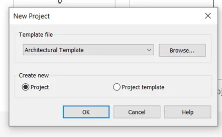
- In Revit, click the File Ribbon tab, hover the mouse over New, and then select Project.
- Select the Architectural template is in list of Project Templates, click Browse.
- In the Choose Template dialog box, navigate to the. rte file you've been working in.Click OK.
- The new "project" and give name as project 2
- Save the project.
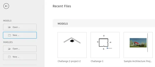
- Create the project. Use a project template provided or use a default template.
- Specify project information, from manager bar and Enter the client’s name, project name, number, and address.
- Define positioning.
- Create construction phases.
- Thus a file is now created and saved with proper information.
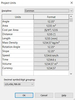
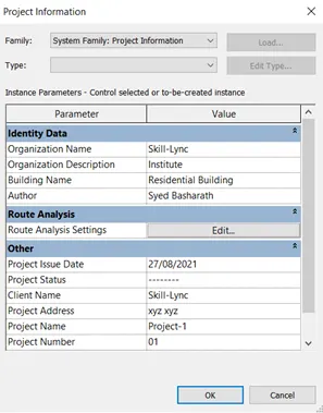
Result: A new File is Created and Project information is filled and saved.
4) Understand the concept of Levels and Grids. Follow the naming and conventions. Create the following Levels: ( Convert to metric equivalents if metric is your units)
Ground Floor @ 0’
First Floor @ 10’
Second Floor @ 20’
Roof @ 30’
Grids Transverse Grids A, B,C,D, E @ 10’ spacing
Longitudinal Grids from 1 to 10 @ 20’ spacing
ANS:
Aim: To Understand the concept of Levels and Grids in Revit.
Tools Used: Save, Manage toolbar, Project information etc.
Procedure:
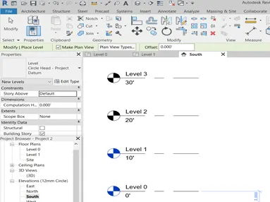
- Open the section or elevation view to add levels to.
- On the ribbon, click (Level). Architecture tab Datum panel (Level)

- Place the cursor in the drawing area and click.
- Draw level lines by moving the cursor horizontally.
- Click when the level line is the correct length that is 10'
- similary do it for other level.
- On the ribbon, click (Grid). Architecture tab, Datum panel(Grid), Structure tab Datum panel (Grid)
- Click Modify | Place Grid tab Draw panel and select a sketch option.
- Use (Pick Lines) to snap the grid to an existing line, such as a wall.
- (Optional) Click Modify | Place Grid tab Draw panel(multi-Segment) to sketch grids requiring more than one segment.
- Click when the grid is the correct length.
- Revitautomatically numbers each grid. To change the grid number, click the number, enter the new value, and press ENTER.
- You can use letters for grid line values. If you change the first grid number to a letter, all subsequent grid lines update appropriately.
- As you draw grid lines, the heads and tails of the lines can align to one another.
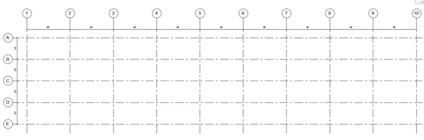
- If grid lines are aligned and you select a line, a lock appears to indicate the alignment.
- If you move the grid extents, all aligned grid lines move with it as shown above.
Result: Levels and grids are Created and marked.
5) 3D modelling of residential unit – From looking at your house / or a place you aspire. Create a conceptual layout of the residential unit. You can measure using a tape or
you can access your residential plan to create a similar layout
ANS:
Aim: Creating a conceptual layout of the residential unit. in Revit.
Tools Used: Architecture toolbar, Wall, Trim, Join etc.,
Procedure:
- Open a floor plan view or a 3D view.
- Click Architecture tab then Build panel then Wall drop-down
- If you want to place a wall type other than the one displayed in the Type Selector, select a different type from the drop-down.
- You can use the bottom part of the Properties palette to modify some of the instance properties for the selected wall type before you start placing instances.
- On the Options Bar, specify the following:
- (3D views only) Select a level for the wall’s base constraint. You can choose a non-story level. See levels.
- Select a level for the wall’s top constraint, or enter a value for the default setting of Unconnected. See height and width.
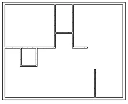
- Draw the wall: Use the default Line tool to place a straight wall segment by specifying both a start point and an endpoint in the drawing.
- Alternatively, you can specify the start point, move the cursor in the desired direction, and then enter a value for the wall length.
- Other tools on the Draw panel let you sketch rectangular, polygonal, circular, elliptical or arced layouts. For detailed descriptions of these tools, see elements.
- As you are drawing a wall with these tools, you can press the Spacebarto flip the interior/exterior orientation of the wall in relation to its location line.
- Place the wall along an existing line: Use the Pick Lines tool to place wall segments along lines you select in the drawing.
- The lines can be model lines, reference planes, or edges of elements, such as roofs, curtain panels, and other walls.
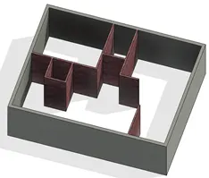
Result: residential unit is Created and 3d view is shown.
6) In the layout created draft the level of details you are planning to include – Dimensions of room, components you plan to add in the residential unit.
ANS:
Aim: Creating and Adding Dimensions to the residential unit. in Revit.
Tools Used: Architecture toolbar, Wall, Door, Window, Join etc.,
Procedure:
After Creation of walls in the drawing now inserting of window and doors,
- In the Architecture tab > Build panel, click Door and windows.
- To insert a tag with each door or window, verify that Tag on Placement is toggled on. You can specify the tag options using the Options Bar.
- Load door families.
- Use the Type Selector to change door types.
- Place doors in the model.
- Use the space bar to change the swing of the door before placing the door.
- Use the flip controls to change the orientation of the door after placing it.
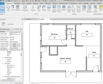
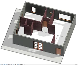
Result: Residential unit is Created, Doors and Windows are installed and 3d view is shown.
7) Identify the residential model elements such as Door, Windows, Tables, Chair, Couch, Bed, Lamps from the library and insert them to the model .
ANS:
Aim: Creating and installing Doors, Windows, Tables, Chair, Couch, Bed, Lamps to the residential unit.
Tools Used: Architecture toolbar, Wall, Door, Window, Insert toolbar, Load Family.
Procedure:
After fixing of doors windows etc now insert furniture,
To load families in the drawing then following procedure is mentioned below.,
- Click Insert tab then Load from Library panel (Load Family).
- In the Load Family dialog, double-click the category of the family that you want to load. In this case use us Family.
- Preview any of the families in the category: To preview a single family, select it from the list. At the top right of the dialog.
- under Preview, a thumbnail image of the family displays.
- To display a thumbnail image in the list for all families in the category, at the top right corner of the dialog, click Views
- Select the family that you want to load, and click Open.
- The family type is now available to place in the project. It displays in the appropriate category under Families in the Project Browser
- The /images are shown below of different elevations.
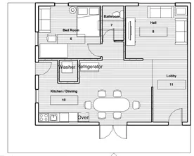
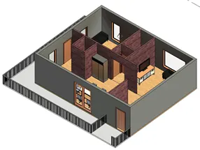
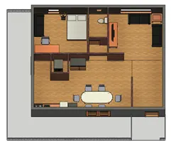
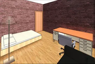
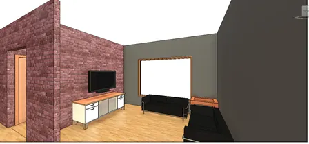
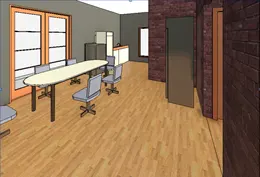
Result: Residential unit is Created, and Installed fully with Furnitures etc and 3d view is shown.