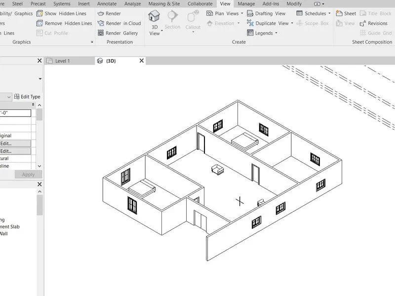
Creating Levels, Grids, Layout and model elements for a residential unit using REVIT
1.BIM
- BIM is a process in which all the information of the 3D buildings Models are linked and incorporated to produce a comprehensive 3D model.
- The BIM is supports to Revit by creating the data based model of architectural designs, structural designs and MEP designs.
Features of BIM
- Revit is a single application built the Building information Modeling with features for Architectural design by using the link of 3D modeling of BIM.
- It enables to understand relationships between spaces, materials, and various system within a physical structure.
- BIM can be used for every step of the process , from planning to design to construction.
- Generative designs, quickly produce design alternative based on goals and constraints your define.
- Parametric components.
- Add ins and Annotation.
- Dynamo for revit.
Benefits of using BIM
- It helps to revolves the issues for convert or creates a 3D from base of 2D , its covered of issues for between of 2D and 3D.
- If we have one model, from which can extract other drawings by using the 3D modeling links.
- Its improve the Onsite collaboration and communication.
- Improving scheduling of designs and drafting.
2.Concept of categories
- It controls the organization, visibility, graphical representations, and scheduling options of families within the project.
- It helps to create a model object tab of the objects styles dialog under category and if we need any groups or family to cover it .
Families
- For this , grouping of 2D or 3D information that serves to represent a discrete building or documentation element in the project.
- And more it helps to design the current model of parametric, graphical, and documentation requirements.
Elements
- The elements is also similar to referred to as families.
- The family contains the geometric definition of the elements and the parameter used by the elements.
- Each instance of an element is defined and controlled by the family.
- Each element you place in a drawing is an instance of a family type.
Instance
- An item from a catalog that is installed in your facility where the properties for that asset are unique to its installation.
3.Creating a project
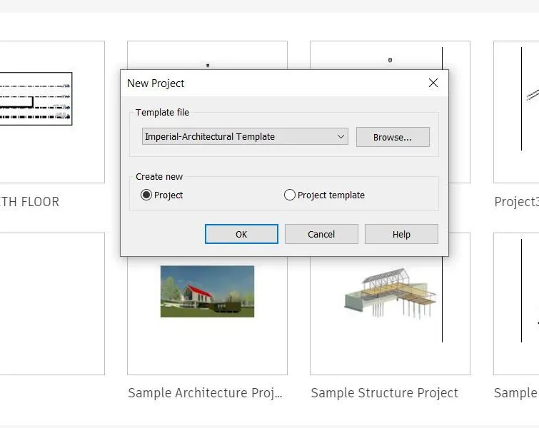
- Click , NEW ‘’ to create a new page with the selection of IMPERIAL ARCHITECTURAL .
- Then, to Save the file with our appropriate name.
- Here, I choose the file name is Residential_floor_plan.
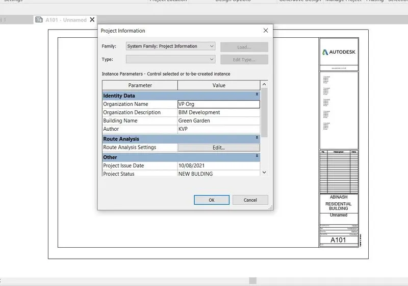
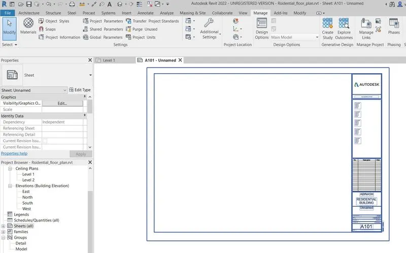
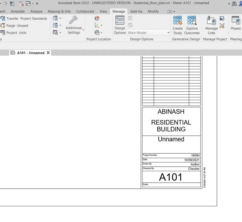
- Take , MANAGE ‘’ tool from the main tool bar, purpose of filling the details of the building.
- Choose , Project information’’ to insert the all data of our project in drawing sheet.
- Its covered the project details and client details.
- Main thing to have all file to get a backup for maximum 3 numbers, after completing the drawing.
4.Concept of Levels and Grids
- GRID - Grid lines are finite planes. This allows you to determine whether grid lines appear in each new plan view that you create for a project.
- LEVEL – Levels are horizontal planes that act as reference for level-hosted elements, such as Roofs, floors and ceiling.
- To create a new page with Imperial architectural .
- To save file at appropriate name.
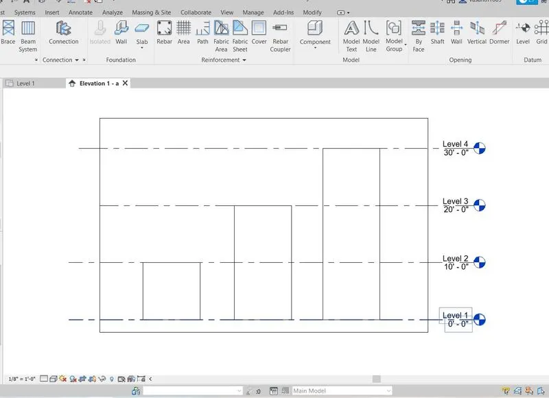
- And then to choose wall Architectural to draw the wall at 10 feet , 20 feet and 30 feet.
- Take toolbar , VIEW’’ to give the elevation of the wall.
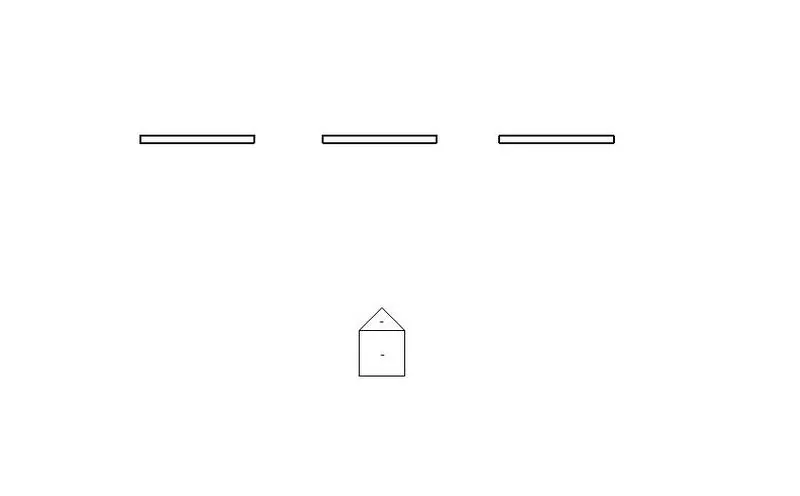
- Go to project browser and to select the Elevation-a, then to view the wall at different height.
- Choose ,, STRUCTURE’ to select the Levels for given the each and every wall top at from the base measurement follows 10 feet, 20 feet and 30 feet.
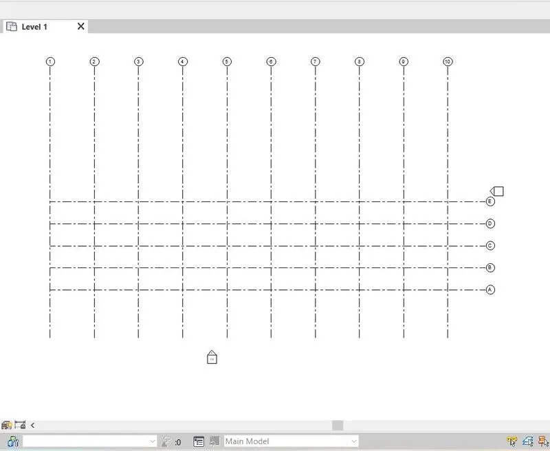
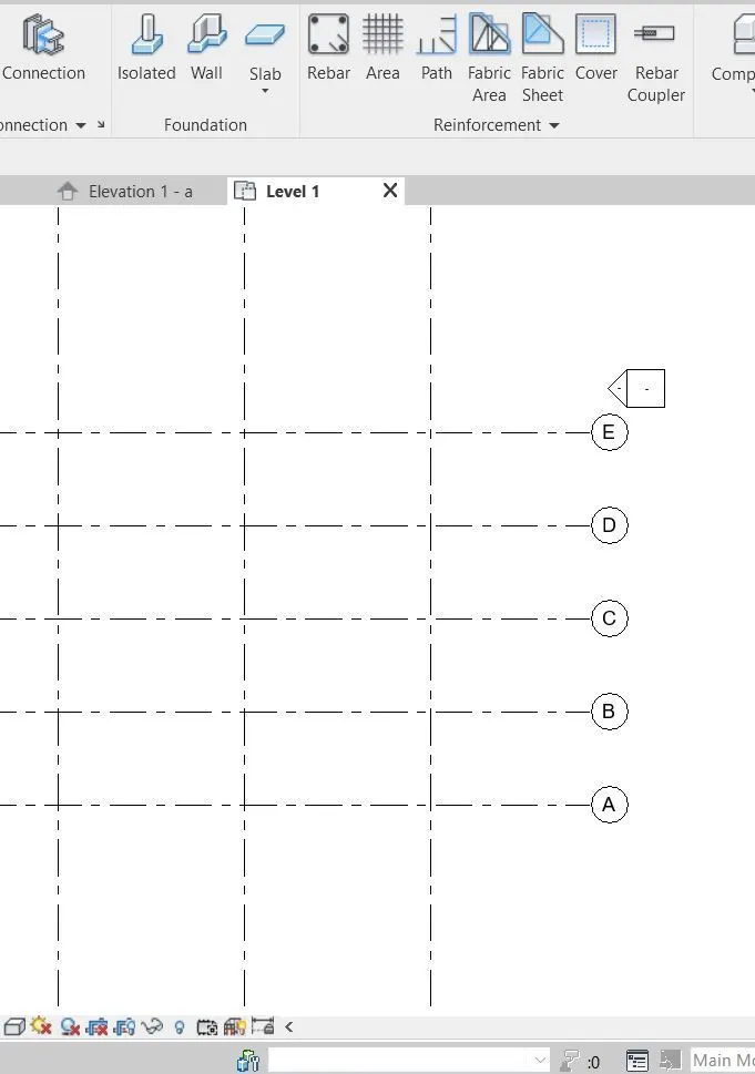
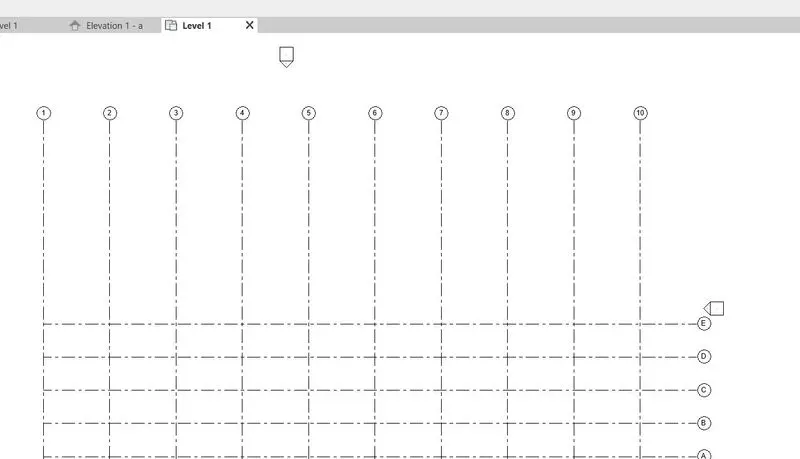
- Similarly, have to select the ‘GRID ‘ to making the construction layout for plan.
- Here, we given Grids in Transverse of the name in A,B,C,D,E @ distance of 10’
- Similarly to Longitudinal Grids from 1 to 10 @ 20’.
5.3D Modeling of Residential unit
- To create a new page with Imperial architectural .
- To save file at appropriate name.
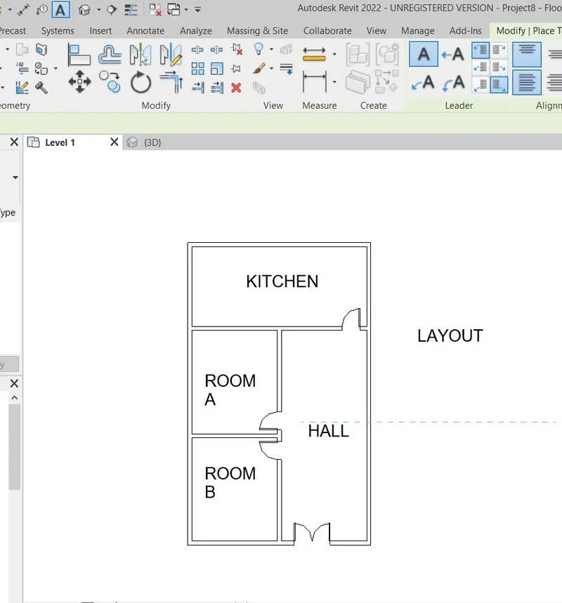
- To create a conceptual layout of residential unit of our plan.
- First to desire the acquired land area of site and to measure the layout area of entire residential area.
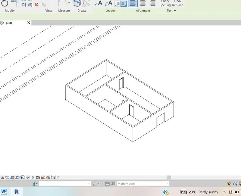
- After creating the layout, then to project browser follow to select the elevation view or to choose from tool bar option of 3D VIEW.
6.Layout of Residential plan
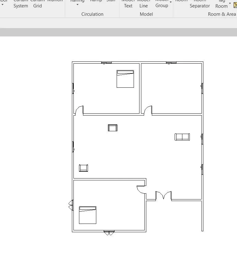
- To create the layout of the residential building with the detailed level of designed building.
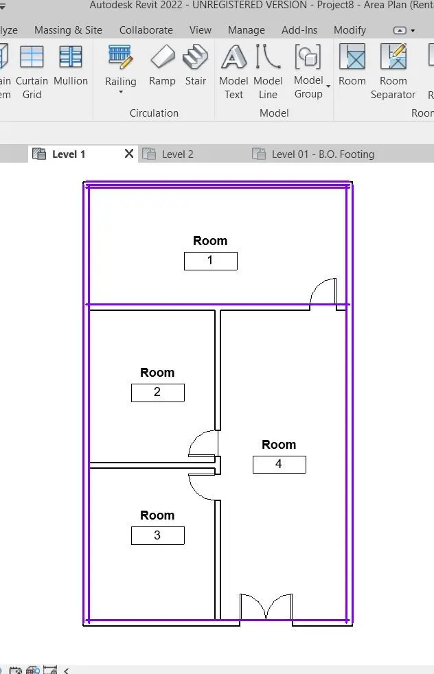
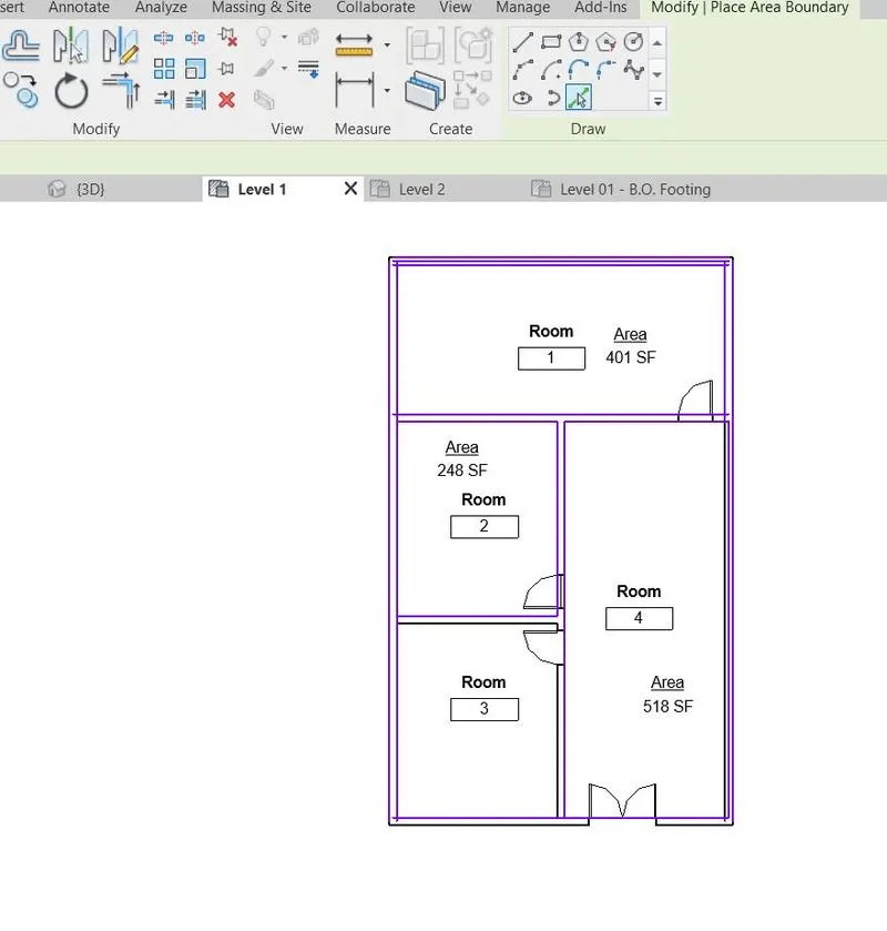
- Through architecture, to create the room with appropriate and to separate the area of the particular area to splitted.
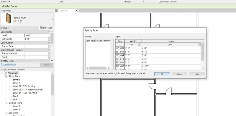
- Choose , Door to add the particular plan for wherever we want for single flush door .
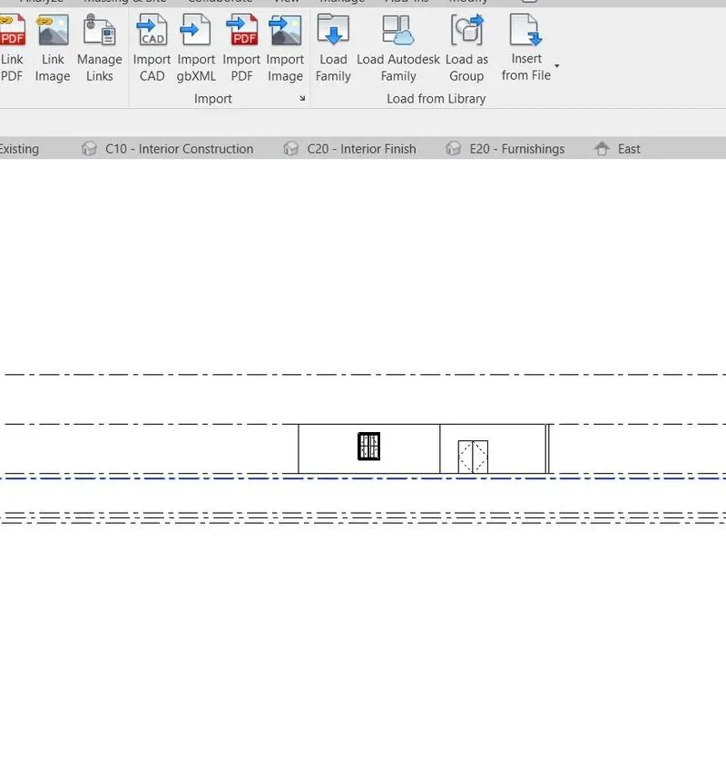
- If we want Double flush door, from to get the templates from our storage of comments at the tool of LOAD FAMILY.
- To select , AREA’ tool to get the area of particular boundary area.
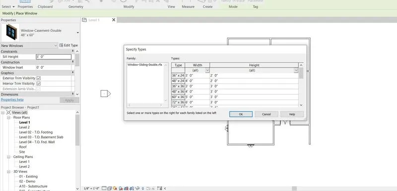
- To select Window to create the window of the wall from where we need it.
7.Residential Model Elements
- To create a layout of plan.
- Then, to add the components of required particular objects.
- To choose Door to want the opening of room, kitchen, etc..,
- If we need Double Flush Door for the main door of residential from LOAD Family templates of content.
- Similarly, to add the Door, Window, Furniture, Lamp, etc.. from library of family elements.