Creating Levels, Grids, Layout and model elements for a residential unit using REVIT
1. What is BIM? Summarize the features of BIM and benefits of using BIM over 2D CAD tools.
Revit platform for building information modeling is a design and documentation system that supports the design, drawings and schedules required for the building project.
Two things lie at the heart of BIM:-
- Collaboration
- Sustainability
Revit building elements are of three types:-
- View elements
- Model elements
- Annotate elements
- Annotation elements
- Datum elements
BIM:-
- BIM is a holistic process of creating and managing information for a built asset. Based on intelligent model an enable by cloud platform bim integrates structed and multi- disciplinary data to produce a digital representation of asset across its life cycle from planning and design to construction operations.
- BIM is a virtual representation of the physical and functional characterstics of a facility from inception onwards. As such, it serves as a shared information repository for collabration throughout a facility's life cycle.
- BIM are computer files (often but not always in proprietary formats and containing proprietary data) which can be extracted, exchanged or networked to support decision-making regarding a built asset. BIM software is used by individuals, businesses and government agencies who plan, design, construct, operate and maintain buildings and diverse physical infrastructures, such as water, refuse, electricity, gas, communication utilities, roads, railways, bridges, ports and tunnels.
- BIM consists mainly of 3D modeling concepts in addition of information database technology and interpolate software in a desktop computer in a enivinorment such as engineer, architect and contractors can be used to set a facilities and simualtes construction. This technology allows members of the project team to generate a virtual model of the structures and allows the system in 3D information in each other.
- BIM allows you to bring all your designs, including CAD models, into a single database. Using the cloud, BIM provides access to this database to all project members. You’ll all work on the same models, which allows for quick changes as needed. When used correctly, BIM helps the entire team visualise the project. In fact, this is one of the main benefits of BIM in construction. The team can spot project issues before construction even starts. That’s because of the sustainability aspect of BIM. The methodology allows you to design every aspect of a building. In addition to the building itself, BIM models feature electrical wiring and other important aspects of design. This creates a more realistic digital representation of the final product.
FEATURES OF BIM:-
- Easy acess to information:- It is the physical representation and functional characterstics of the building process that provide very minute detail of the project.
- Making the process more expensive:- Making the process more expressive. CAD software allows the user to work accurately in 3D dimensions that is length, depth and breadth. However, BIM modeling services provide us allow to work in 5 dimensions that is time and cost. Apart from length, breadth and depth. BIM allows us to work in 5 dimensions that is time and cost. Thus, they provide accurate cost and material estimates. Precise time schedule of the project even the design is been developed.
- Comprehensive view of the project:- It represents the 3D geometry of the structure. They provide the more comprehensive view of the entire building process. Actually it covers every component of the process from geometrical aspects of the design to spacial relationship from light analysis to provision of various services from topographical information to quantities and properties and so on.
BENIFITS OF BIM OVER 2D CAD TOOLS:-
- Complete Representation:- BIM offers a more complete representation of a building’s design. It takes more than the building’s core components into account. For example, BIM allows you to design electrical and HVAC systems, as well as the building itself. This means the project team can take full advantage of the space and resources available.
- Instant Updates:- BIM allows us to provide instant updates of whole the components. BIM pulls your documents into a single database. Several people can work on the same model and save it to the cloud. This allows for instant updates, so you won’t waste time searching for documents when you need to make changes.
- Time Constraints:- BIM allows us time constraint. A BIM model will allow you to prefabricate important components ahead of time. You won’t have to adjust them based on the building design. Instead, such components are part of the initial design.
- Resource Tracking:- Resource tracking is a key component of BIM models. You’ll be able to figure out how much of each resource you need during the design stage. This improves the flow and efficiency of construction. You can provide much more to your clients using BIM than you could with CAD. The models you give to your clients update constantly as you work on your project. Your client can check in any time, which leads to quicker approval for milestones and more efficient project development.
__________________________________________________________________________________________
2. Understand the concept of Categories, Families, Elements, Instances in Revit. Go to Insert Tab, choose a category. Pick a family and element. Understand the instances and insert it to Revit model.
CATEGORY:-
- Category is a revit element hierarchy. Actually it controls the organization, visibility, graphical representations and scheduling options of families within project.
FAMILY:-
- A Family is a grouping of 2D and/or 3D information that serves to represent a discrete building or documentation element in the Project. It defines parametric, graphical, and documentation requirements.
TYPE:-
- Type is a specific representation in a family defined by distinct parametric, graphical and documentation characterstics which make it unique from other types in the family.
INSTANCES:-
- An Instance is an individual representation of a Type in the Project defined by unique parametric, graphical, and documentation characteristics which makes it unique from other Instances in the Project. Tool bar from which we will load family that is either category, family, type and instances.

- In REVIT 2023, we can't directly load family. To work with categories, families, types and instances at first we have install load families version content from Autodesk Revit.
- To install it first go to HELP / F1 - on right side downloads shown click on it - After that the next windows gets opened - Scrool down - Click on the link called US English content family labraries in Imperial and metric and then download it.
- After the installation start extracting.
- After the extraction process completed then click on finish and then click on exit.
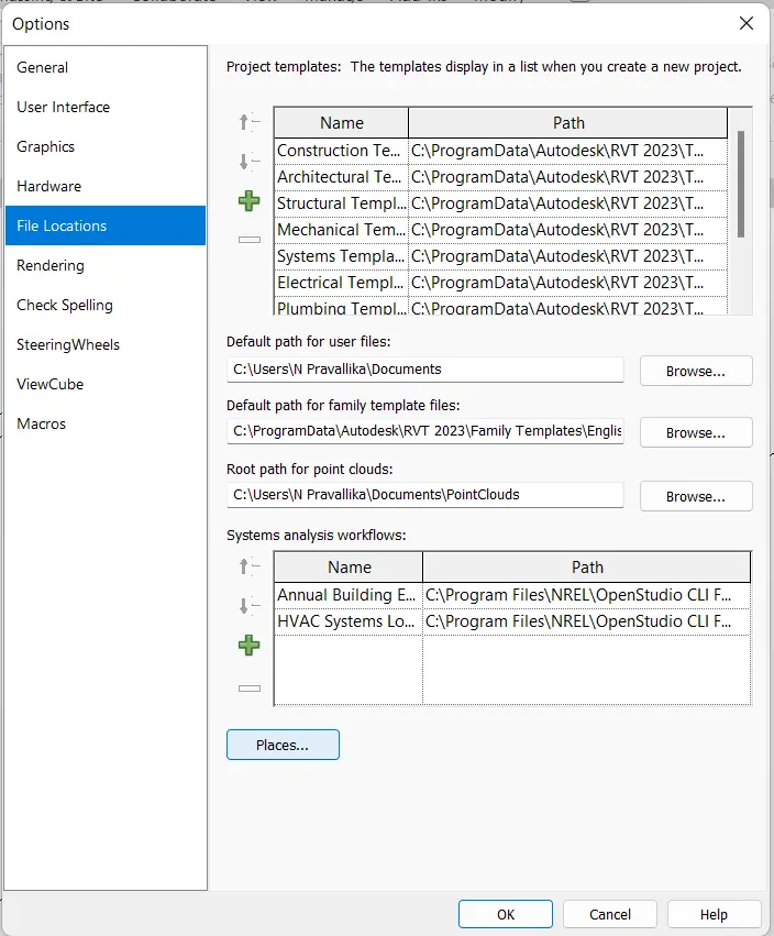
- Now open REVIT 2023, Check wheather load family is working or not. If not then go to files and then click on options. A window get opened as shown below.
- Next click on File location. In the same window bottom side there is a option called places click on it.
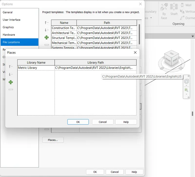
- After that a window is opened in which labraries are present. Check wheather the year shown is 2022 are not if not change the year from 2023 to 2022. Now the path is going to change. Now, we can work it load family tab.
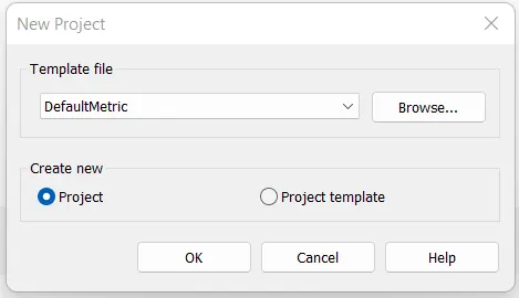
- Again exit from the window and Open the new template that is default one which we can get by browsing it.
- Go to Architecture tab - Click wall and draw the with assume lengths in rectangle shape.
- To attach door use the tab called load family.
- Next on RVT 2022 - Library - English imperial - US - Next obtained tab is shown below.
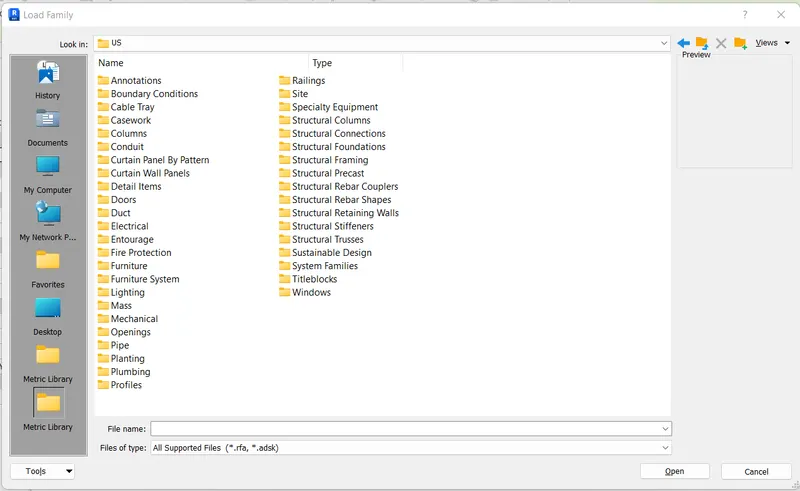
- Whatever displayed in the above window those are termed as Category.
- Whatever displayed in Category is termed as Family. That is either in Door, window or annotate etc. Family windows are shown below.
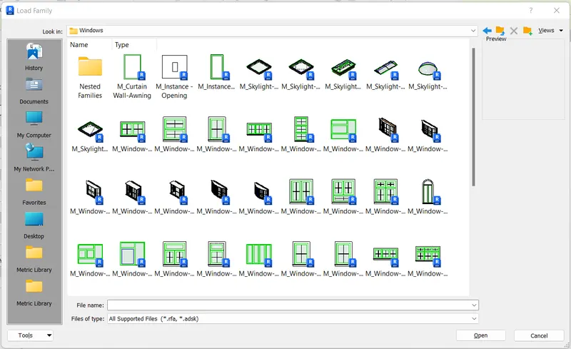
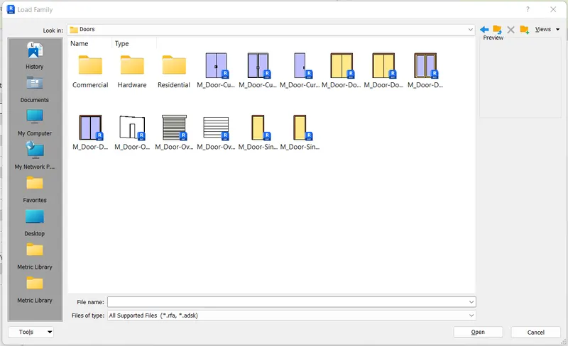
- Types are the building blocks of a 3D model.
- They represent the real-world components that a designer adds to the model.
- Some elements such as walls, windows, and beams are 3D and appear in all views.
- You can think of these elements as components that exist in a building.
- Other elements such as tags, dimensions, or other annotations appear only in the view in which they are placed.
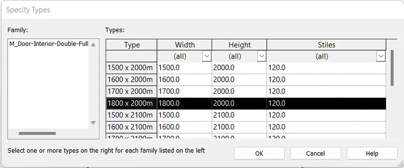
- For example we select the family from the door catagory, after selecting the family the new tab will visible.
- Next there will be different sizes of door is there, select any one of them.
- Next that element is applied to the 3d model, and it will appears in the properties tab at the left side of the screen, as shown below.
- Instances are individual graphical/geometric elements placed in a Revit model e.g. a single Wall, or a single Door, or any other single element.
- As a subset of Revit Elements, Instances inherit a series of Parameters from their Category and Type and might have instance parameters as well that only belongs to that single instance.
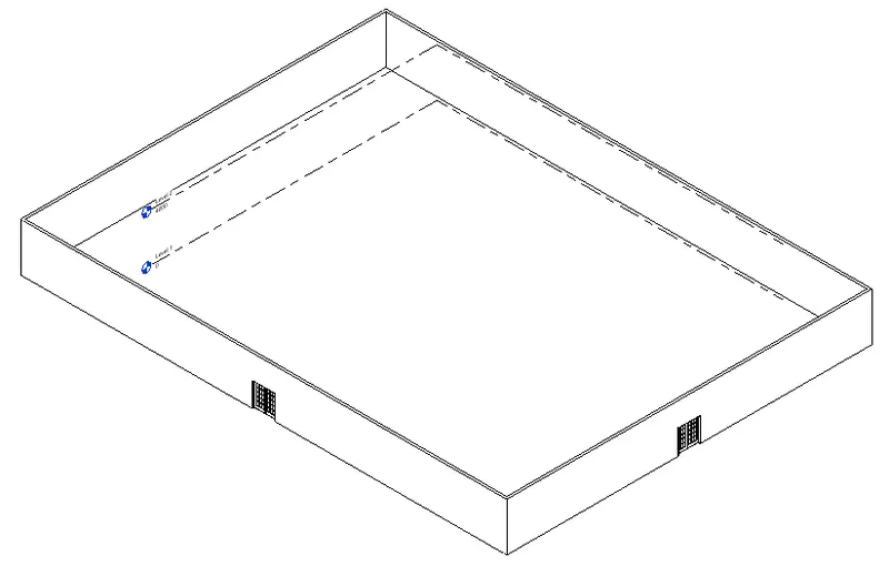
- The single element attatched to the wall is door, that door we call as instance, as shown below in result.
__________________________________________________________________________________________
3. Setting up a Project – Open a project file with architectural template. Save the file with appropriate name. Set up the project units to Imperial / Metric based on your convenience of modelling. Complete the project information under Manage tab. Set up the maximum backups for project file to 3.
AIM:-
- To Set up a Project
- To Set the template of Project file with architectural
- To save the file with approriate name
- To set up the project unit to Imperial / Metric
- To set up Project information under manage tab.
- To set up 3 Backup file in a project.
INTRODUCTION:-
- Specify project information such as project name, status, address, and more. Click Manage tab Settings panel Project Information. In the Instance Properties dialog, specify the following: Energy Settings.
- Click Manage tab Settings panel Project Information.
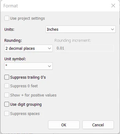
- To change units in Revit you will need to use the Project Units dialog to set project units. Project Units. In the Project Units dialog, select the discipline. Select the value in the Format column to change the display value for that unit type.
- Each time you save locally and synchronize to the central model a backup file is created. Your local backups folder will generally be saved in your documents folder on your machine. The backups folder for the central file will be in the same folder as the Revit model file.
PROCEDURE:-
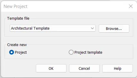
- For setting a project. we need to select the architectural template for modeling the architectural plan.
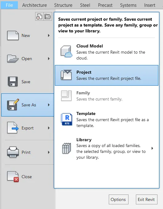
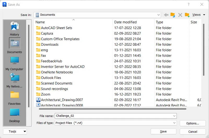
- If we save the file with appropriate name, the name will be saved to the particular folder as shown below.
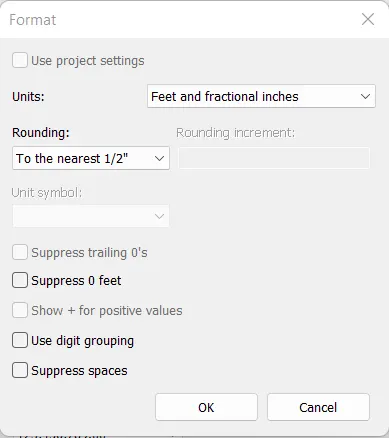
- The project units toolbar is used to set the project units, that applies to the whole project.
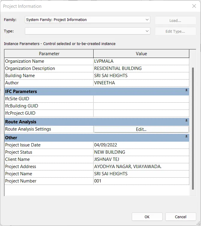
- To open the project information tab, first go to manage tab, in that is there is a option called project information.
- The project information option is used to save the information of the project, by entering the project name, project issue date, project status, project address etc.
- To setup backup files, go to save as option and in file tab.
- Then, a save as dialog box will be appearing on the screen.
- On right side bottom there tab called option.
- Click on it to set the backup files.
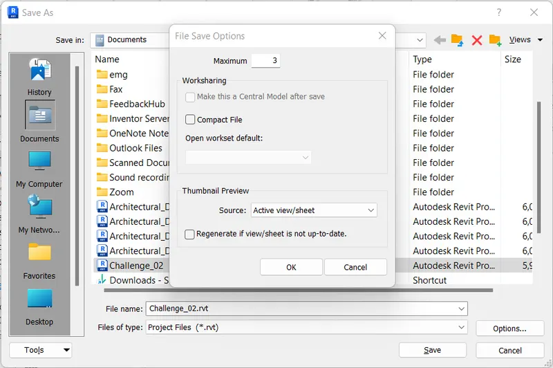
- Here the maximum backup files taken is 3 as per mentioned.
- Click on ok.
RESULT:-
- Project set up is done
- The template of Project file with architectural is done
- The file name is saved with approriate name
- The project unit is changed to Imperial / Metric
- The Project information under manage tab is done.
- The 3 Backup file in a project is done.
__________________________________________________________________________________________
4. Understand the concept of Levels and Grids. Follow the naming and conventions. Create the following Levels: ( Convert to metric equivalents if metric is your units)
Ground Floor @ 0’
First Floor @ 10’
Second Floor @ 20’
Roof @ 30’
Grids Transverse Grids A, B,C,D, E @ 10’ spacing
Longitudinal Grids from 1 to 10 @ 20’ spacing
AIM:- To create the grids and levels using the given details.
INTRODUCTION:-
- Levels and grids are finite planes that help to define project context. Add levels. Create a level for each known story or other reference needed for the building design.
- Use the Level tool to define a vertical height or story within a building. You create a level for each known story or other needed reference of the building (for example, first floor, top of wall, or bottom of foundation). To add levels, you must be in a section or elevation view.
- Grid lines are datums that are used as references or guidelines for a building model. Creating a framework of grid lines early in the project can help you as you develop your model. To place a grid line, on the Architecture tab, click Grid.
- As we start to construct our 3D model, we need some method of controlling the vertical height of our elements- be it floor heights, the base and top of columns, window cill heights, etc. This is where Levels come into play. In order to create an effective and efficient model, it is crucial that you understand the use of Levels. The correct use of Levels will ensure that your model can readily be adjusted with the minimum of effort.
PROCEDURE:-
STEP1:- To create the levels
- Open REVIT 2023, Click on new to create a revit model and then a 'New Project' dialogue box is opened to create the template file as per requirement.
- In this challenge the template opted is 'Architectural Template' and then click on project and then click on OK.
- For creating the levels, first we select the 'Level 1' and followed by double click on 'East' in (Elevations Building) in the project browse.
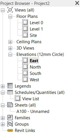
- Now, two basic levels will be displayed on the screen.
- Keep the bottom most level and delete the second level.
- In Architecture tab there is a option called level.
- The project units toolbar is used to set the project units, that applies to the whole project.
- Below Ribbon there is a option called offset. Enter the offset value as 10' and then in ribbon right side there is option called pick point.

- Click on pick point and then click on level to offset the respective level in that direction.
- Give offset in same way in the same direction with the offset distance as 10', 20' and 30'.
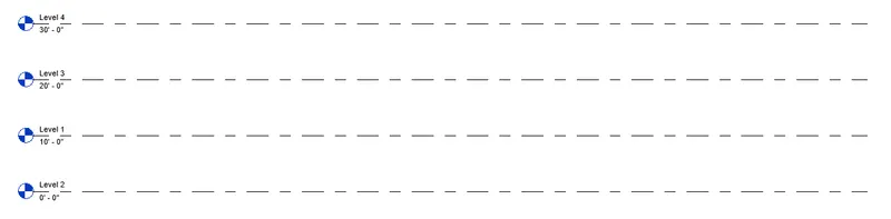
- Now rename the levels as ground floor, first floor, second floor and roof.
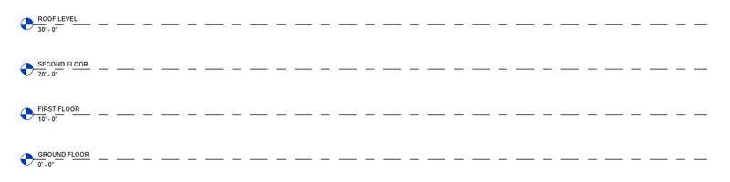
- The renamed layers are ground floor, first floor, second floor and roof. The made figure is shown in the result.
- Levels and grids are created as per the given details.
STEP2:- To Create the grids
- Open REVIT 2023, Click on new to create a revit model and then a 'New Project' dialogue box is opened to create the template file as per requirement.
- In this challenge the template opted is 'Architectural Template' and then click on project and then click on OK.
- The project units toolbar is used to set the project units, that applies to the whole project.
- Change the units to inches.
- In Architecture tab there is a option called grids.
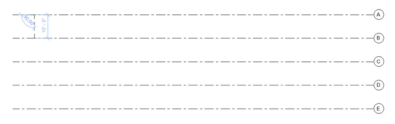
- Next we draw the grid lines horizantally, indicating the grids with the name A, B, C, D, E.
- Below Ribbon there is a option called offset. Enter the offset value as 10' and then in ribbon right side there is option called pick point.
- Offset with same distance that is 10' for 5 times.
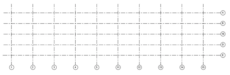
- Next we draw the grid lines vertically, over the horizontal grid and then indicate the grids with the name 1 to 10.

- Below Ribbon there is a option called offset. Enter the offset value as 20' and then in ribbon right side there is option called pick point.
- Offset with same distance that is 20' for 10 times.
RESULT:-
- Levels are created and attached as follows.
- Grids are created and attached as follows.
__________________________________________________________________________________________
5. 3D modelling of residential unit – From looking at your house / or a place you aspire. Create a conceptual layout of the residential unit. You can measure using a tape or
you can access your residential plan to create a similar layout.
AIM:- To create a conceptual layout of the residential unit in the revit.
INTRODUCTION:-
- Three-dimensional (3D) models represent a Physical body using a collection of points in 3D space, connected by various geometric entities such as triangles, lines, curved surfaces, etc.
- Being a collection of data, 3D models can be created manually, or by scanning.
- Their surfaces may be further defined with texture mapping.
PROCEDURE:-
- First we have to draw the residential layout with the standard dimensions with the help of wall tool in architectural tab.
- The outer wall thickness is opted as 150mm and the inner wall thickness as 200mm.
- While drawing architectural residential layout use trim/extand command trim the wall whereever it is required and extend command to extend the wall whereever it is required.
- To trim/extend the wall, select the wall which is not need trim, then other side will automatically trimmed off.
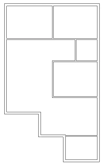
- In Architectural tab, click on floor tool using line command draw the outer line to make floor.
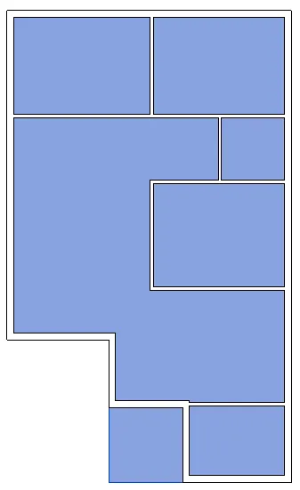
- Next add dimensions to the layout plan, shown below in the result.
- Windows and doors are attached from Architectural tab using windows and doors tool.
- After placing windows and doors the figure is shown in the result.
RESULT:-
The conceptual layout of the residential unit in the revit is created and figure is shown below.
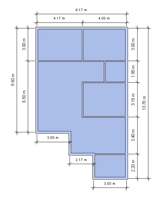
__________________________________________________________________________________________
6. In the layout created draft the level of details you are planning to include – Dimensions of room, components you plan to add in the residential unit.
AIM:- To draft the level of details which include dimensions of room, components to add in the residential unit.
INTRODUCTION:-
- Dimensioning on a floor plan usually requires two or three continuous dimension lines to locate exterior walls, wall jogs, interior walls, windows, doors, and other elements.
- Exterior walls of a building are dimensioned outside the floor plan. The outermost dimension line is the overall building dimension.
- The next dimension line, moving toward the plan, indicates wall locations and centerlines to doors and windows.
- Other miscellaneous details in the plan are located on a third dimension line.
PROCEDURE:-
- From the previous drawn residential unit, we put the dimensioins for the rooms, as shown below.
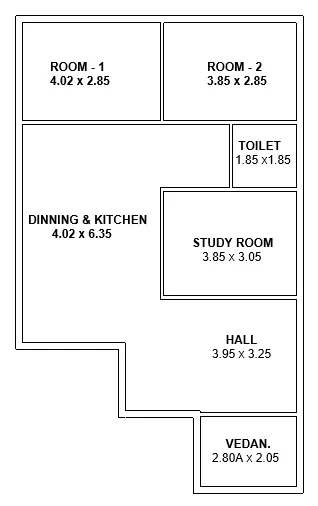
- Next we need to add the doors to the layout using the door option in the architecture toolbar.
- Next we need to add the windows to the layout using the window option in the architecture toolbar.
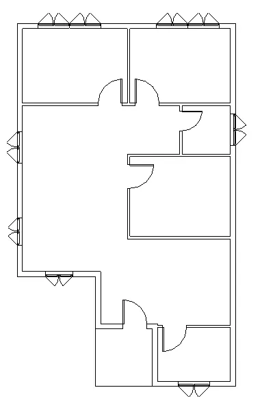
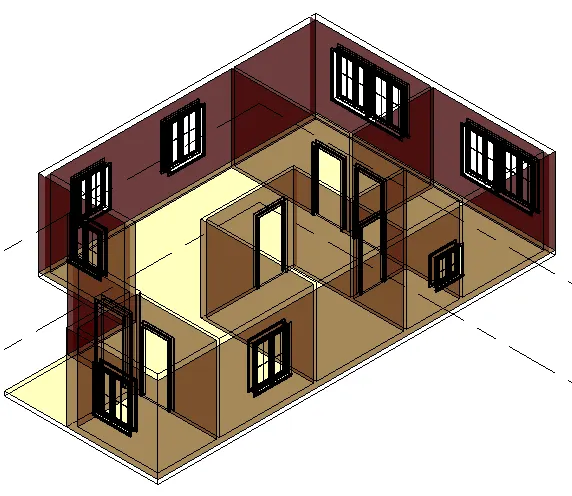
- Next the residential unit is changed to the three dimensional view, as shown below in result.
RESULT:-
- Next the residential unit is changed to the three dimensional view, as shown below.
- The level of details which include dimensions of room, components are successfully added in the residential unit.
_________________________________________________________________________________________
7. Identify the residential model elements such as Door, Windows, Tables, Chair, Couch, Bed, Lamps from the library and insert them to the model . Save the project for use,for Assignment 3
AIM:- To insert the residential model elements such as Door, Windows, Tables, Chair, Couch, Bed, Lamps from the library to the model. Need to save the project for use.
INTRODUCTION:-
- The residential model elements are door, windows, chair, couch, bed, lamps.
- These elements are very important in the building model for construction.
- Comming to the 3d modeling in the revit, these elements are present in the library and we need to insert them into the model.
PROCEDURE:-
- After the doors and windows added to the layout using the door option and window option in the architecture toolbar.
- Next from the insert tab in the toolbar. By using load family tool load the furniture whereever is required.
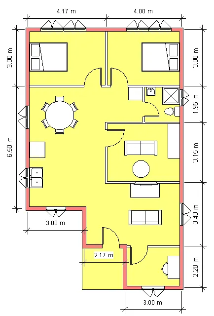
- Change the plan to 3d view.
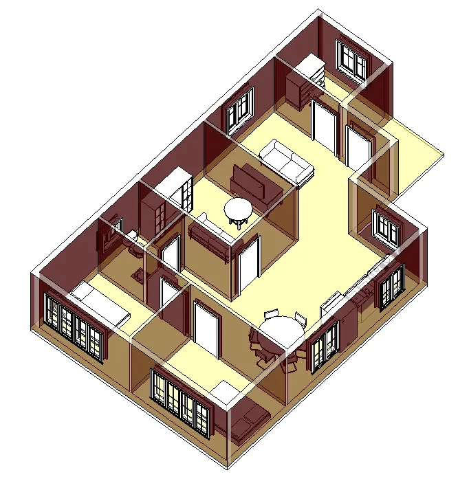
- The all model elements are inserted successfully and the layout plan is turned to the different views, as shown below.
- For better visibility the 3d view cutted in to 2 views as shown below.
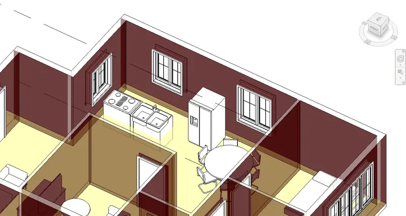
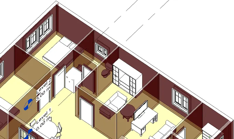
RESULT:-
The residential model is created and then elements are added such as Door, Windows, Tables, Chair, Couch, Bed, Lamps from the library and inserted them to the model.
_________________________________________***THE END***____________________________________