Drafting of various geometries using Chamfer, Fillet tool in AutoCad
Q. Drafting of various geometries using Chamfer, Fillet tool in AutoCad
AIM:- To draft given sketches in autocad using various tools.
INTRODUCTION:-
Autocad offers various tools to perform different tasks. The various tools which are used for drafting in this project are briefly described.
COMMANDS USED:
- Line
- Circle
- Chamfer
- Fillet
- Offset
- Rotate
- Object Snap
- Trim
- Extend
- Lengthen
- Mirror
- Join
- Arc
- Points
- Construction Line
LINE:
- Line is a handy key in autocad which is used frequently. It creates a series of contiguous line segments. Each segment is a line object that can be edited seperately.
- Type command "l" in command box and then click on enter to get a line. To specify first point-Sets the starting point for the line and click a point location with object snaps or grid snaps turn on, then place the point precisely. We can also enter the coordinates based on the requirement.
- That is how a new line starts. To specify the endpoint of line segment. We can also use polar and object snap tracking together with direct distance entry or from any one the coordinate methods.
- If we use line to create a polygon then there is a command "C" enter (Close) used to connect the first and last segments.
- If not there is a command which is displayed on cammond box while working with line tool that is undo whic is used to remove the most recent segment of a line sequence.
CIRCLE:
- To create a circle type the command "c".
- Specify the centre point to create a circle based on the requirement centre point is defined either by radius or diameter. That is enter the value to specify a point that is coordinate (x,y) and then the value, or specify the next point.
- There are different ways to create a circle.
- 3P (Three points)
- Tan, Tan, Tan
- 2P (Two points)
- TTR (Tangent, Tangent, Radius).
CHAMFER:
- To create a chamfer type the command "cha".
- An angled line that meets the endpoints of two straight 2D objects.
- It is sloped transition between two surface. In order to get the surface as chamfered the specify the horizontal and veritical distance or specify the distance and angle.
- Select the objects in such way that the requirement is reached.
FILLET:
- To create a fillet type the command "f".
- The fillet tool helps form round corners between any two entities that form a sharp vertex. A round or fillet can be created between two objects of the same or different object types: 2D polylines, arcs, circles, ellipses, elliptical arcs, lines.
- If the two selected objects are on the same layer, the arc defined is created on that layer. Otherwise, the arc is created on the current layer. The layer affects object properties including colour and line type.
OFFSET:
- To create a offset type the command "o".
- Specify the offset distance through which it is required. Select the object to offset.
- The offset command in AutoCAD is used to create parallel lines, concentric circles, and parallel curves.
- The offset objects can also be modified further according to the requirements. Here, modification of offset object means that we can apply trim, extend, and other methods on it.
ROTATE:
- To rotate an object type the command "ro".
- Select the objects you wish to rotate and press Enter to accept the selection.
- Specify the base point around which you want to rotate them.
- Type an angle to rotate the objects by or use the cursor to indicate an angle.
OBJECT SNAP:
- Object snaps provide a way to specify precise locations on objects whenever you are prompted for a point within a command.
- The command used is "os" - object snap or F3 function key.
- We can use object snaps to create a line from the centre of a circle to the midpoint of another line. The available options are endpoint (end), midpoint (mid), centre (cen), geometric centre (cen), nearest (nea), quadrant of a circle (quad), intersection, perpendicular, tangent, parallel, extension, apparent intersection, nodes, insertion points etc.
TRIM:
- To trim a object the command used is "tr"
- In general trim is used to trim edges and that is possible only if there is intersection.
- There are two modes that is quick mode and standard mode.
- Quick Mode:- To trim objects, select the objects to be trimmed individually, press and drag to start a freehand selection path, or pick two empty locations to specify a crossing Fence. All objects automatically act as cutting edges. Selected objects that can't be trimmed are deleted instead.
- Standard Mode:- To trim objects, first select the boundaries and press Enter. Then select the objects to be trimmed. To use all objects as boundaries, press Enter at the first Select Objects prompt.
EXTEND:
- To extend the object the command used is"ex".
- Extends objects to meet the edges of other objects.
- To extend objects, first select the boundaries. Then press Enter and select the objects that you want to extend. To use all objects as boundaries, press Enter at the first Select Objects prompt.
LENGTHEN:
- To lengthen the object the command used is "lengthen".
- Changes the length of objects and the included angle of arcs.
- We can specify changes as a percentage, an increment, or as a final length or angle. LENGTHEN is an alternative to using TRIM or EXTEND.
MIRROR:
- To mirror the object the command used is "mi".
- Create a mirrored copy of selected objects.
- We can create objects that represent half of a drawing, select them, and mirror them across a specified line to create the other half.
JOIN:
- To join the object the command used is "j".
- Joins the endpoints of linear and curved objects to create a single object.
- Combines a series of finite linear and open curved objects at their common endpoints to create a single 2D or 3D object. T
- he type of object that results depends on the types of objects selected, the type of object selected first, and whether the objects are coplanar.
ARC:
- To create arc of an object the command used is "a or arc ".
- To create an arc, you can specify combinations of centre, endpoint, start point, radius, angle, chord length, and direction values.
- Arcs are drawn in a counter clockwise direction by default. Hold down the Ctrl key as you drag to draw in a clockwise direction.
POINTS:
- To create point of an object the command used is "ptype or dpptype".
- Creates a point object. Point’s objects can act as nodes to which you can snap objects.
- We can specify 2D and 3D locations for a point.
- The current elevation is assumed if you omit the Z coordinate value.
- The PDMODE and PDSIZE system variables control the appearance of point objects.
CONSTRUCTION LINES:
- To create construction line of an object the command used is "xl".
- Construction lines (also known as xlines) are temporary linework entities that can be used as references when creating and positioning other objects or linework.
- Construction lines are either circles or straight lines that extend to infinity in both directions.
Q1.
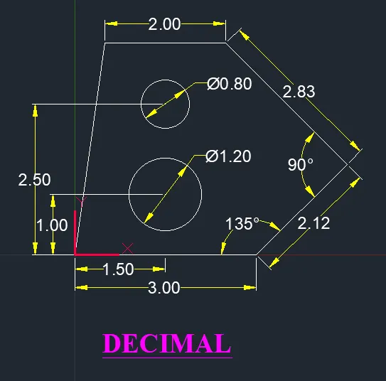
AIM:- To draft the following using decimal system of units.
PROCEDURE:-
- Create a new sheet.
- Change units to decimal, click on the precision to 0.00 and the dimension to meter and then ok.
- Change the limits from (0,0) to (420,120).
- Zoom-All
- Select the line and draw the length, specify the first point as (0,0) and followed by (@3<0) to get the base line.
- Specify the next point as (@2.12<45), (2.83<135), (@2<180) and close it using closing command.
- To sketch the circle, select the circle command and then draw the circle by specifying the coordinate as (1.5,0) and specify the diameter as 1.20 units.
- Similarly, draw another circle with the coordinate as (1.50,2.50) and followed by diameter 0.80 units.
- Annotate and give dimension to the line segments and circles.
- Change the Dimension style based the requirement.
- Use the command as mtext to create the text.
RESULTS:-
The given sketch is drafted in autocad and attached below as shown:
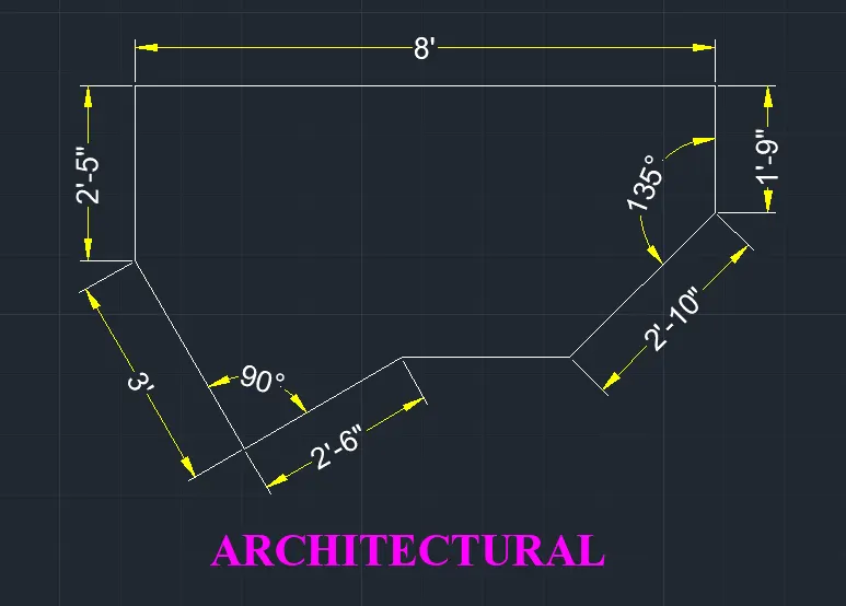
AIM:- To draft the following using architectural system of units.
PROCEDURE:-
- Create a new sheet.
- Change units to architectural, click on the precision to 0'-0" and the dimension to feet and then ok.
- Change the limits from (0'-0",0'-0") to (12'-0",10'-0").
- Zoom-All
- Select the line command and draw the length, specify the first point as (0'-0",0'-0") and followed by (@8'<0) to get the base line.
- Place the cursor at (0'-0",0'-0") and specify the next point as (@2'-5"<270) and Place the cursor at (@8'<0) and specify the next point as (1'-9"<270).
- Place the cursor at (@2'-5"<270) and specify the next point as (@3'<120) and (2'6"<30).
- Press Esc to come out of the command box.
- Select the line command and Place the cursor at (1'-9"<270) to draw the length (2'10"<225) and close it using closing command.
- Annotate and give dimension to the line segments and circles.
- Change the Dimension style based the requirement.
- Use the command as mtext to create the text.
RESULTS:-
The given sketch is drafted in autocad and attached below as shown:
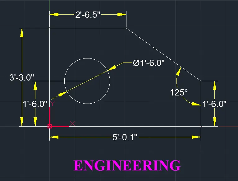
AIM:- To draft the following using architectural system of units.
PROCEDURE:-
- Create a new sheet.
- Change units to engineering, click on the precision to 0'-0" and the dimension to feet and then ok.
- Change the limits from (0'-0",0'-0") to (12'-0",10'-0").
- Zoom-All
- Select the line command and draw the length, specify the first point as (0'-0",0'-0") and followed by (5'-0.1") to get the base line.
- Place the cursor at (0'-0",0'-0") and specify the next point as (@3'-3.0"<90), (2'-6.5"<180)
- Place the cursor at (5'-0.1") and specify the next point as (@1'-6"<90), ortho off and close it using closing command.
- Select the circle commnd and draw the circle with the coordinates (1'-3.0",1'-6.0") and the specify the diameter as 1'-6.0"
- Annotate and give dimension to the line segments and circles.
- Change the Dimension style based the requirement.
- Use the command as mtext to create the text.
RESULTS:-
The given sketch is drafted in autocad and attached below as shown:
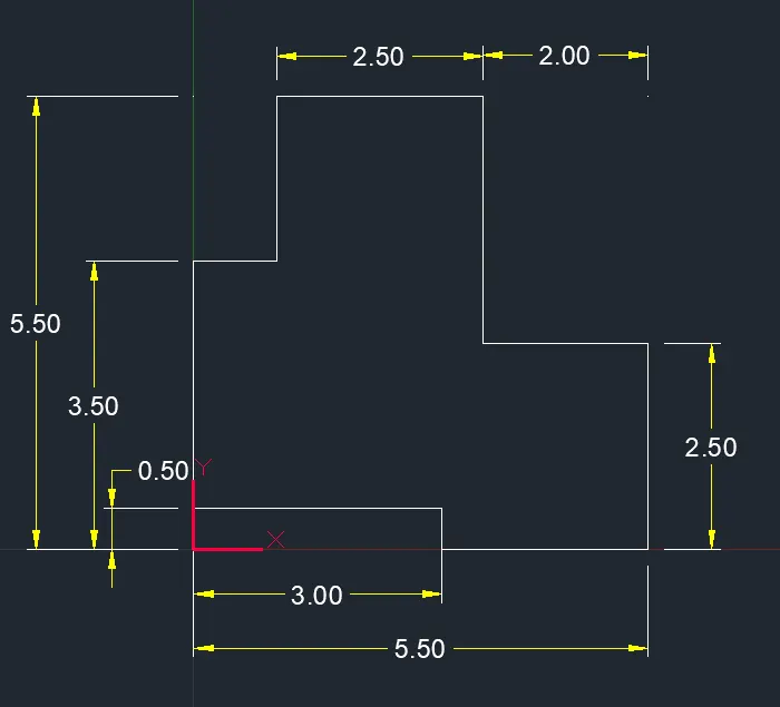
AIM:- To draft the following using decimal system of units.
PROCEDURE:-
- Create a new sheet.
- Change units to decimal, click on the precision to 0.00 and the dimension to meter and then ok.
- Change the limits from (0,0) to (420,120).
- Zoom-All
- Select the line and draw the length, specify the first point 2.50 units to get the base line. Press Esc to come out of the command.
- Place the cursor at left side of line segment of length 2.50 units. Specify the next point as (@2.00<275), (0.5<180), (@3.50<270), (@3.0<0), (@0.50<270), (@2.50<0), (@2.50<90), (@2.00<180) and close it using closing command.
- Annotate and give dimension to the line segments and circles.
- Change the Dimension style based the requirement.
- Use the command as mtext to create the text.
RESULTS:-
The given sketch is drafted in autocad and attached below as shown:
AIM:- To draft the following using decimal system of units.
PROCEDURE:-
- Create a new sheet.
- Change units to decimal, click on the precision to 0.00 and the dimension to meter and then ok.
- Change the limits from (0,0) to (420,120).
- Zoom-All
- Select the "rec" command and draw rectangle 11.5*6.0. Press Esc to come out of the command Type Ex command, select rectangle to explode it.
- Select the "o" command to offset, select the vertical length 6.0 units of offset at a distance 3.0 units on both sides of the rectangle. Press Esc to come out of the command.
- Select the "o" command to offset, select the vertical length 6.0 units of offset at a distance 2.75 units. Press Esc to come out of the command.
- Select the "o" command to offset, select the horizontal length 11.50 units of offset at a distance 3.00 unit. Press Esc to come out of the command.
- Select the circle commnd and draw the circle with the coordinates (1.50,3.0) and the specify the diameter as 2.0 units. Again the select the circle command with same coordinate and specify the the diameter for inner circle is 1.0 units.
- Select "co" command to copy the circle and paste at the coordinate (10.0,3.0) that is at the mid point.
- Select the circle commnd and draw the circle with the coordinates (5.75,3.0) and the specify the diameter as 3.0 units.
- Annotate and give dimension to the line segments and circles.
- Change the Dimension style based the requirement.
- Use the command as mtext to create the text if required.
RESULTS:-
The given sketch is drafted in autocad and attached below as shown:
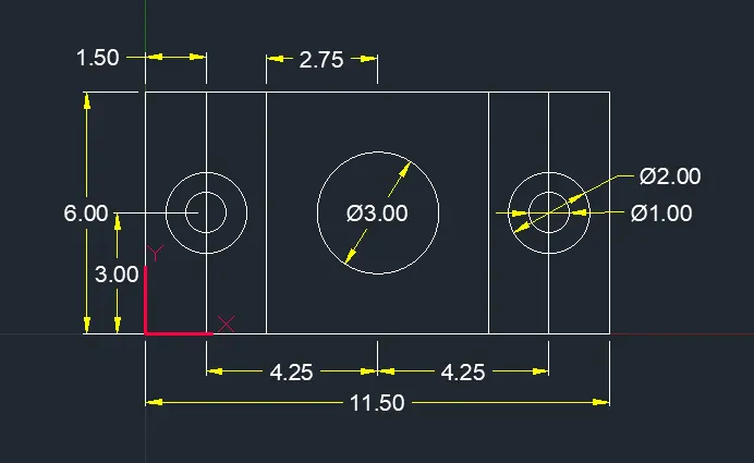
AIM:- To draft the following using decimal system of units.
PROCEDURE:-
- Create a new sheet.
- Change units to decimal, click on the precision to 0.00 and the dimension to meter and then ok.
- Change the limits from (0,0) to (420,120).
- Zoom-All
- Select the line and draw the length, specify the first point as (0,0) and followed by (1.5,0) to get the base line.
- Select the "o" command to offset the base line made to the distance 0.50 unit and to 1.50 unit. Press Esc to come out of the command.
- Select "l" command to draw the boundary line as required. Again select the offset command 1.0 unit to obtain the same to get the three segments
- Select "l" command to draw the length 2.0 units at top right of the section. Specify the next point as (@1.5<90),(@2.0<180) and C enter to close the command.
- Select the "o" command to offset the vertical length to distance 0.50 unit and to 1.50 unit. Press Esc to come out of the command. Press Esc and again select offset command offset the horizontal distance 1.5 units to the distance 0.5 units(twice).
- Select the line command and draw the length 2.0 units and specify the next point as (@1.50<90), (@0.5<180), (@1<270),(@1<180) and (@0.5<270). Press Esc and again select the line command to draw the slant line joining two points as shown.
- Change the Dimension style based the requirement.
- Use the command as mtext to create the text.
RESULTS:-
The given sketch is drafted in autocad and attached below as shown:
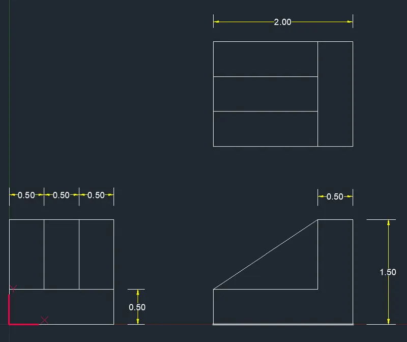
AIM:- To draft the following using decimal system of units.
PROCEDURE:-
- Create a new sheet.
- Change units to decimal, click on the precision to 0.00 and the dimension to meter and then ok.
- Change the limits from (0,0) to (420,120).
- Zoom-All
- Select line command and draw a line of base 210 units, now give the line command 100 units vertical line on left side, since arc has radius of 35 units draw line of 70 units towards right side. Press Esc
- now give the line command 70 units vertical line on right side, since arc has radius of 25 units draw line of 50 units towards left side. Press Esc
- Select the command arc and from start, end and radius an arc of radius 35 units on left side and repeat the same process on right side with the arc radius as 25 units.
- Select circle command, from mid point of 70 units horizontal line on left side draw a circle of diameter 50 units and 30 units on right side.
- Select the command offset and offset 210 units line at a distance of 60 units.
- Select the command fillet and fillet radius 15m on top right and left and radius of 20 units on inner left and radius of 6units on inner right.
- Select the command offset and offset 210 units line to 100 units and 75 units line to 20 units.
- Select the command rectangle and draw a rectangle of length 70 units and 30 units width from offset line on both sides.
- Use trim command to remove unwanted lines from the drawing as shown.
RESULTS:-
The given sketch is drafted in autocad and attached below as shown:
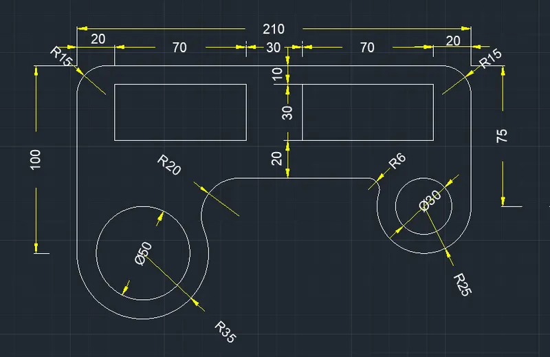
AIM:- To draft the following using decimal system of units.
PROCEDURE:-
- Create a new sheet.
- Change units to decimal, click on the precision to 0.00 and the dimension to meter and then ok.
- Change the limits from (0,0) to (420,120).
- Zoom-All
- Select the command circle and draw a concentric circle of diameter 5.00 units and 4.00 units.
- Select the commmand line and draw a line of 4.275 units from the center point on both sides.
- Select the command circle and draw a circle of dia 0.90 units on both sides.
- Select the command arc and from start, end and radius draw an arc of radius 0.90 units on both sides.
- Select the line command to make the line tangent.
RESULTS:-
The given sketch is drafted in autocad and attached below as shown:
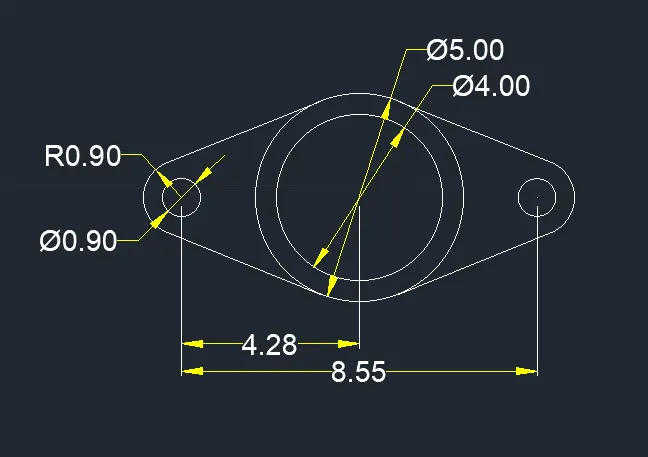
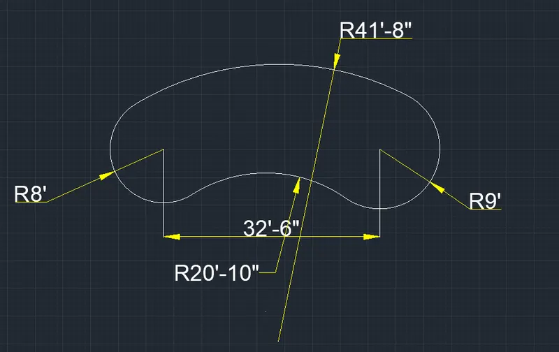
AIM:- To draft the following using decimal system of units.
PROCEDURE:-
- Create a new sheet.
- Change units to decimal, click on the precision to 0.00 and the dimension to meter and then ok.
- Change the limits from (0,0) to (420,120).
- Zoom-All
- By using direct entry method, a line is drawn.
- Select the Line command and pick up the first point and give dimension as 32-’6” for the next point
- Select circle from Ribbon and pickup starting point of the line as center point of the circle and give radius as 8’ to form the smaller circle and with the same center point and procedure give radius as 33-’8” to form outer circle
- Select circle from Ribbon and pickup end point of the line as center point of the circle and give radius as 9’ to form a circle and with the same center point and procedure give radius as 32’-9” to form outer circle.
- Again, enter C in the command pickup bottom intersection points of the two bigger circle as center point of the circle and give radius as 41’8” to form a circle which gives the top arc of the given geometry.
- Select circle command Ribbon and select Tangent, Tangent, Radius option
- Pickup Tangent point from both smaller circle and give radius as 20’-10” to form the bottom arc of the geometry
- Now select Erase and erase both bigger circles
- Select Trim command and select crossing and trim the other shaps which is other than the given geometry.
RESULTS:-
The given sketch is drafted in autocad and attached below as shown:
AIM:- To draft the following using decimal system of units.
PROCEDURE:-
- Create a new sheet.
- Change units to decimal, click on the precision to 0.00 and the dimension to meter and then ok.
- Change the limits from (0,0) to (420,120).
- Zoom-All
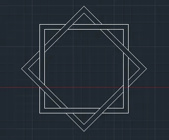
- Select Rectangle tool from the Ribbon, Select a starting point and give dimension length as 10 units and width as 10 units to form a square.
- Select offset and select the object, rectangle and give offset distance as 0.5 to form offset lines.
- Select Copy tool and select whole geometry and click a base point and copy it nearby.
- Select rotate command and pick up a base point and give rotate angle as 45 and press enter.
- Select Move command, select rotated object and pick up the center point of it and move to the middle point of the first square.
- Select Trim command the trim the object which is other than the geometry.
RESULTS:-
The given sketch is drafted in autocad and attached below as shown:
AIM:- To draft the following using decimal system of units.
PROCEDURE:-
- Create a new sheet.
- Change units to decimal, click on the precision to 0.00 and the dimension to meter and then ok.
- Change the limits from (0,0) to (420,120).
- Zoom-All
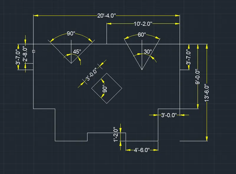
- By using direct entry method, the lines are drawn.
- Select Rectangle tool and specify the starting point and give dimension length as 20’-4” and width as 13’-6” to form a rectangle.
- Select L command in the command line and pickup the midpoint of the length of the rectangle and draw a perpendicular line.
- Select L command and pick up the right corner point of the rectangle and move <90 and give dimension length as 4’-6”
- Move cursor to the <180 and give dimension length as 3’.
- Move cursor to the <270 and give dimension as 4’-6.
- Move cursor to the <90 and give dimension as 1’-2” and close the line to the perpendicular middle line.Select Mirror command and select the line other than the rectangle which drawn earlier and pick the bottom point of the rectangle as base point and move it to to top to form the mirror image.
- Select Polar tracking in the status bar.
- Select L command and pick middle point of the top right half of the rectangular and draw a line dimension of 3’-7” and move cursor to the <270From that point track <60 and draw a line meeting the rectangle.
- Again, from the same point track <120 and draw a line touching rectangle.Select L command and pick middle point of the top left half of the rectangular and draw a line dimension of 2’-8”” and move cursor to the <270.
- From that point track <45 and draw a line meeting the rectangle.
- Again, from the same point track <135 and draw a line touching rectangle.
- Select L command and pick left corner point of the rectangle as starting point and move cursor to the <270 and enter dimension as 6’-9”.
- Move cursor to the <0 and draw line dimension of 20’-4”.
- Select rectangle command and pick the random point out side the rectangle and draw a rectangle of dimension length as 3’ and width as 3’.
- Select Rotate command and select the small rectangle and enter rotate angle as 45..
- Now pick the center of the rotated rectangle and move to the intersecting point of middle line of rectangle and horizontal center line by the Move command.
- Select Trim command and trim all other objects other than the given geometry.
RESULTS:-
The given sketch is drafted in autocad and attached below as shown:
________________________________________________________________________***THE END***_________________________________________________________________