Creating Levels, Grids, Layout and model elements for a residential unit using REVIT
1) What is BIM? Summarize the features of BIM and benefits of using BIM over 2D CAD tools.
Ans 1: BIM is a visual representation of the physical and functional characteristics of a facility from inception onwards. As such, it serves as a shared information repository for collaboration throughout the facility’s lifecycle. It can be used from the start of planning of project to completion of the project.
Benefits of the BIM and features are as follows
- Easy access to information. It provides all the details of project
- Making process more expressive. It helps working in 5 dimensions, 3D plus time and cost factor.
- Comprehensive view of the project. It helps visualise the complete project by showing all the services
- Complete representation. It can represent the details from all disciplines.
- Instant updates. It reveals instant changes and updates of all the disciplines.
- Time constraint. It helps proper planning of all the services and help track project.
- Resource tracking. The estimation of resources required for various activities can be worked out.
2) Understand the concept of Categories, Families, Elements, Instances in Revit. Go to Insert Tab, choose a category. Pick a family and element. Understand the instances and insert it to Revit model
Ans.2. The following concepts define, documentation graphical and parametric characteristics of the elements
Category- It controls the organization of families in Revit for 2D or 3D elements and helps in scheduling activities. Example : Door is a category
Family – It is group of 2D or 3D elements which represents the different elements. Example : Single Flush door is a Family
Type – It is specific representation of the elements in the family. EXAMPLE: Specific size of the Single flush door
Instances-It is individual representation of the elements in type. EXAMPLE: A door placed in the drawing wall
INTRODUCTION: Familiarizing with the Category, Family, Elements and Instances
AIM: To choose Category, load Family, select Elements and insert the Instances in the Revit Project drawing using Insert tab.
PROCEDURE:
- Go to Insert tab and select Load Family
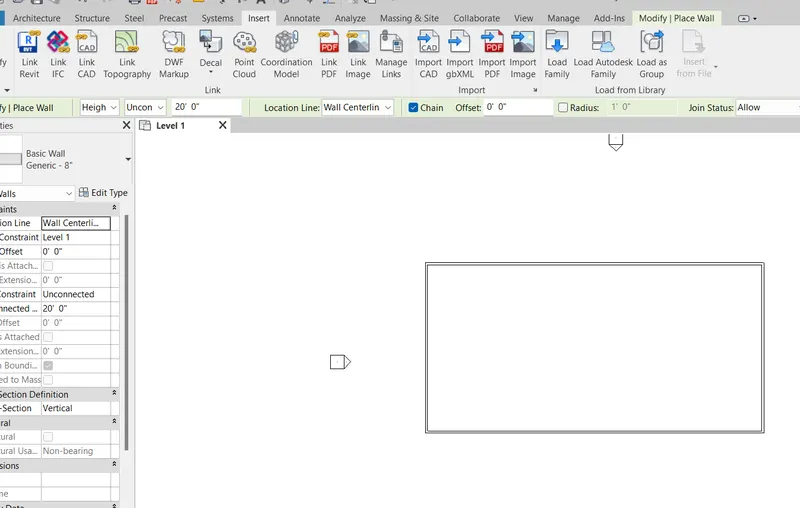
- Load Family in the current file
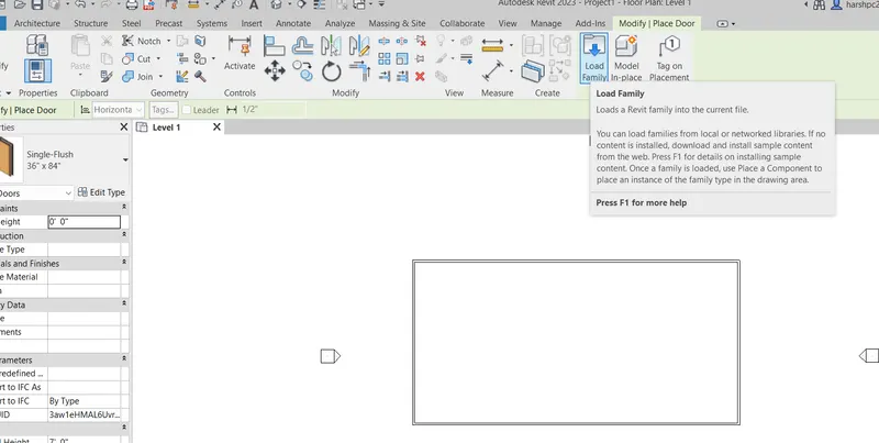
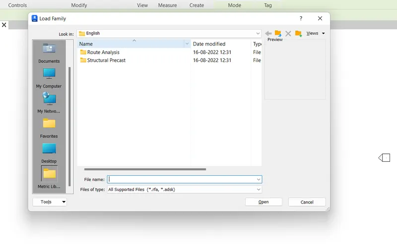
- From Drop Down list select the required Family to be loaded
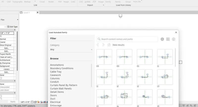
- If the required family is not available, seek from the Autodesk website by Revit Content Library
- The Categories will be listed as shown below
- Category of Door shown below and Family of Single Flush door as shown below
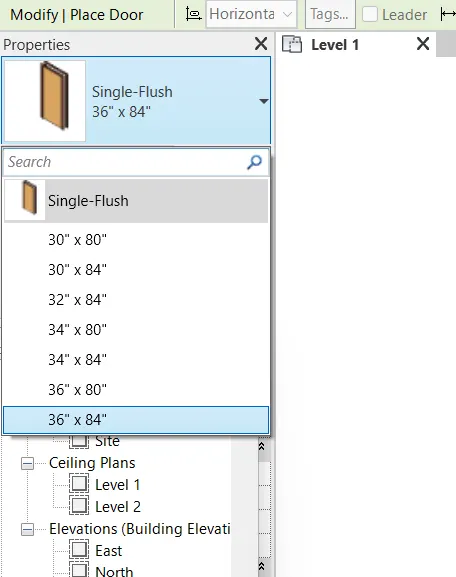
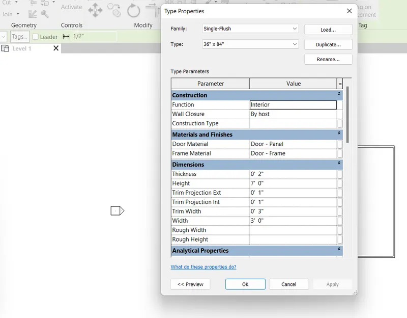
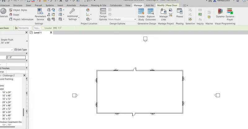
- Flush door element of size 36" x 84" shown below
- Instances of Door and Window elements inserted in the drawing
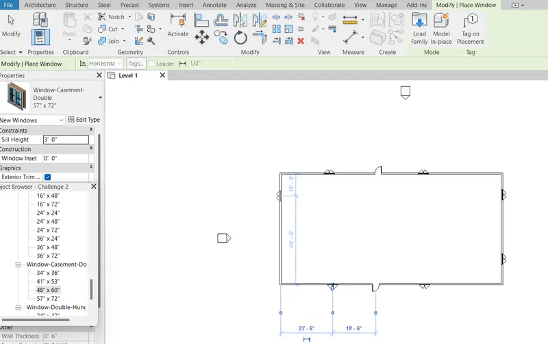
CONCLUSION: Thus using the various Revit tools we have carried out the task of understanding and using the Category, Family, Elements and Instances in the Project.
3) Setting up a Project – Open a project file with architectural template. Save the file with appropriate name. Set up the project units to Imperial / Metric based on your convenience of modelling. Complete the project information under Manage tab. Set up the maximum backups for project file to 3
Ans 3:
Introduction : Project file setting up and using various features learned.
AIM: To open a project file with architectural template and saving the file with appropriate name. Setting up the project units to Imperial / Metric as per requirement. Completing the project information using Manage tab. Setting up the maximum backups for project file to 3
PROCEDURE:
- Open the Revit file from the architectural template created earlier and saved as Challenge 2
- The default units is selected to Imperial from the Program files.
- However the individual units can be changed to required Metric or Imperial from Manage tab and clicking on the Project units in settings and changing the units for individual parameters as required
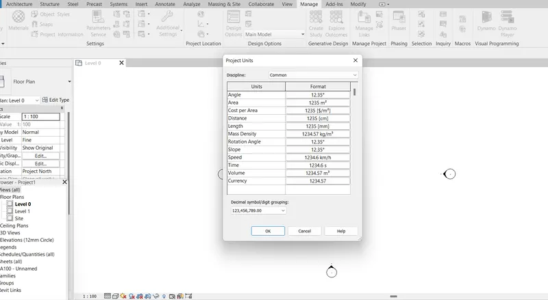
- For setting up the Project information, Click on Manage tab
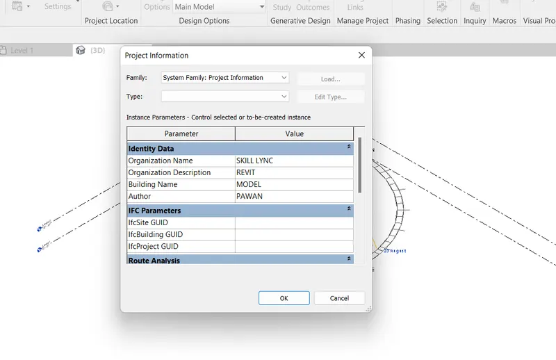
- Click on the Project Information icon in Settings
- Project information can be entered as shown below
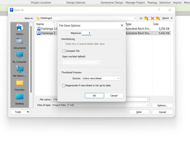
- From File Menu, click on Save as tab
- The window will pop up prompting for the Save in location and File name location
- Click on the Options tab.
- In File Save Options change the setting of maximum saves to 3 back ups
- Click Ok
- Then click on Save, the file is saved with the given name and in the required folder selected.
CONCLUSION: Thus we have opened a project file with architectural template and saved the file with appropriate name. We have set up the project units to Imperial / Metric as per requirement. We have Completed the project information using Manage tab and Set up the maximum backups for project file to 3 as shown in the screenshots
4) Understand the concept of Levels and Grids. Follow the naming and conventions. Create the following Levels: ( Convert to metric equivalents if metric is your units)
Ground Floor @ 0’
First Floor @ 10’
Second Floor @ 20’
Roof @ 30’
Grids Transverse Grids A, B,C,D, E @ 10’ spacing
Longitudinal Grids from 1 to 10 @ 20’ spacing
Ans 4:
INTRODUCTION: Creating Levels and setting up of Grids
AIM : To create the 4 levels GF, FF, SF & Roof of 10' height each and providing the transverse and longitudingal grids as required.
PROCEDURE:
- Open the project file.
- Go to the Elevation tab in the Project browser
- Default 2 levels are visible
- Change the level 2 to 10'
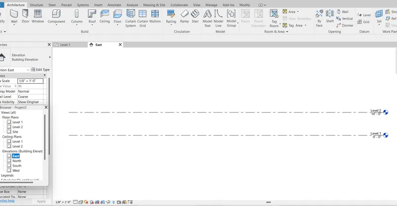
- Click on Level 1 and rename it to Ground floor and level as 0'
- Click on Level 2 and rename it to First floor and ensure that level is 10'
- Click on the Level icon in the ribbon to add a level and enter value of offset as 10'
- Click on upper side of First floor level
- Level 3 will be created
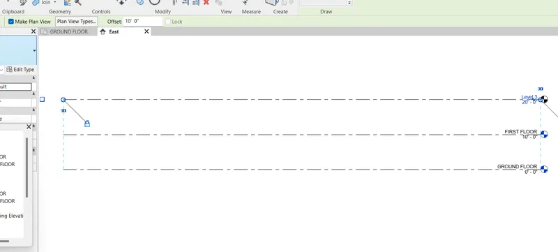
- Rename level 3 to Second Floor
- Create one more level at 10' offset and rename it to Roof
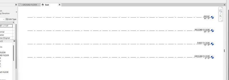
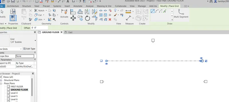
- Go to floor plan at Ground floor
- Click on Grid and create a horizontal grid line for transverse grid
- Click again on grid to create more grid line and offset by 10'
- Similarly create 5 transverse grids from top to bottom and rename the grids to A to E from top to bottom
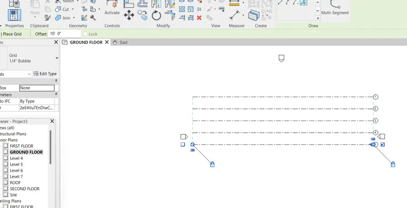
- Again click on the grid and create a vertical grid on the left side of the horizontal grid lines
- Create further more grids with 20' offset to create 10 vertical or longitudinal grids
- Rename the grids from 1 to 10 from left to right
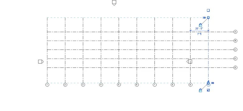
CONCLUSION: Thus we have created 4 levels as required in the challenge as given details and created the transvers and longitudinal grids as per the given details and configure transverse grids from top to bottom and longitudinal grids from left to right for numbering sequence.
5) 3D modelling of residential unit – From looking at your house / or a place you aspire. Create a conceptual layout of the residential unit. You can measure using a tape or
you can access your residential plan to create a similar layout.
Ans 5.
INTRODUCTION: Creating 3D model of residential unit by creating a Conceptual layout of residential unit.
AIM: To create a conceptual layout of the residential unit with appropriate dimensions, providing floor levels for the residential unit and further use to create 3D model of the residential unit.
PROCEDURE:
- Open a new Revit project file with Architectural template.
- Save the file with name for project and the required back ups.
- Create a floor plan for the residential unit
- Draw walls with required height for the residential building
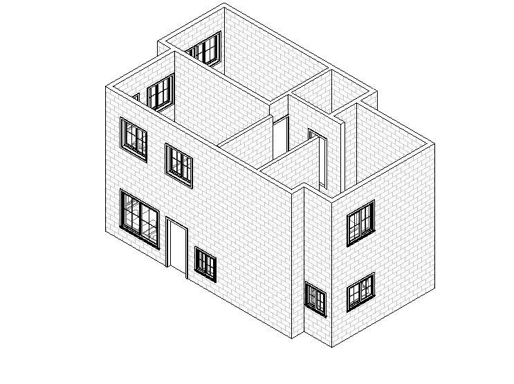
- Click on the 3D icon on the top of ribbon to see the 3D view of the drawng floor plan details.
- The detailed levels and components are added in the next solution and 3D view shown in solution of next answer to question 6.
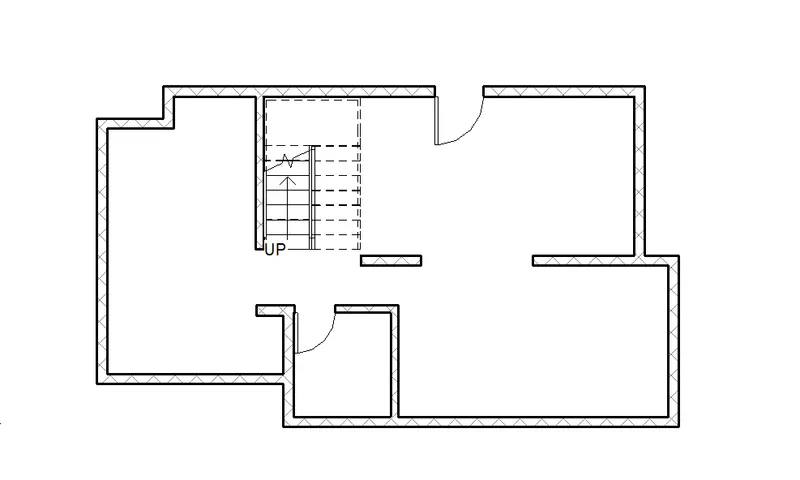
CONCLUSION: Thus conceptual layout of the residential unit is created at ground floor for creating the 3D model of the residential unit.
6) In the layout created draft the level of details you are planning to include – Dimensions of room, components you plan to add in the residential unit.
Ans 6.
INTRODUCTION: Creating 3D model of residential unit by creating a Conceptual layout of residential unit.
AIM: To provide levels to the conceptual layout of the residential unit created in previous task. Providing dimensions to the plan of residential unit created and adding components to the the residential unit
PROCEDURE:
- In the previously created floor plan for residential unit, click on the elevation and create levels for First floor and Roof as shown below.
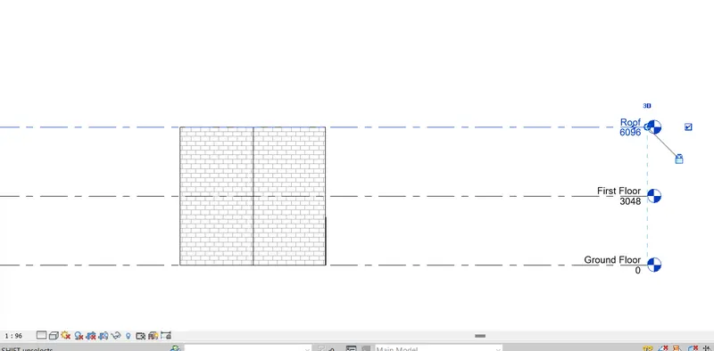
- Provide the dimensions to the room detail plan using Annotate tab.
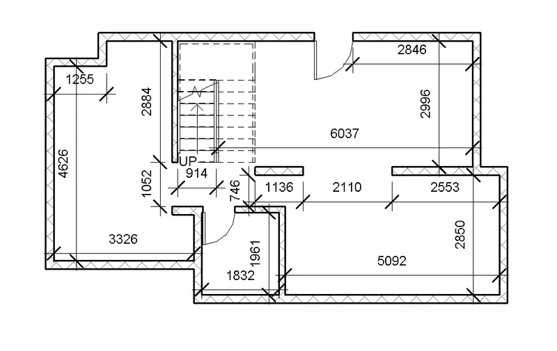
- Provide the room tags by selecting the room boundaries and name the rooms and room number is created.
- Add the Windows and doors elements of appropriate size as requred to the floor plan by assiging proper sill levels to the windows.
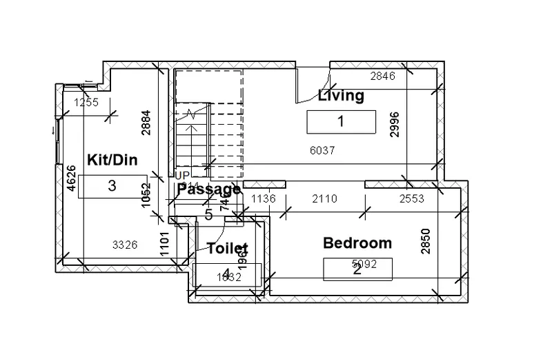
CONCLUSION: Thus we have provided levels to the conceptual layout of the residential unit created in previous task. We have also shown dimensions to the plan of residential unit created and added components to the the residential unit.
7) Identify the residential model elements such as Door, Windows, Tables, Chair, Couch, Bed, Lamps from the library and insert them to the model . Save the project for use
for Assignment 3
Ans 7.
INTRODUCTION: Creating 3D model of residential unit by creating a Conceptual layout of residential unit.
AIM: To provide the residential model elements such as Door, Window and furniture elements into conceptual layout of the residential unit created in previous task by inserting from the library to model. Saving the project for use.
PROCEDURE:
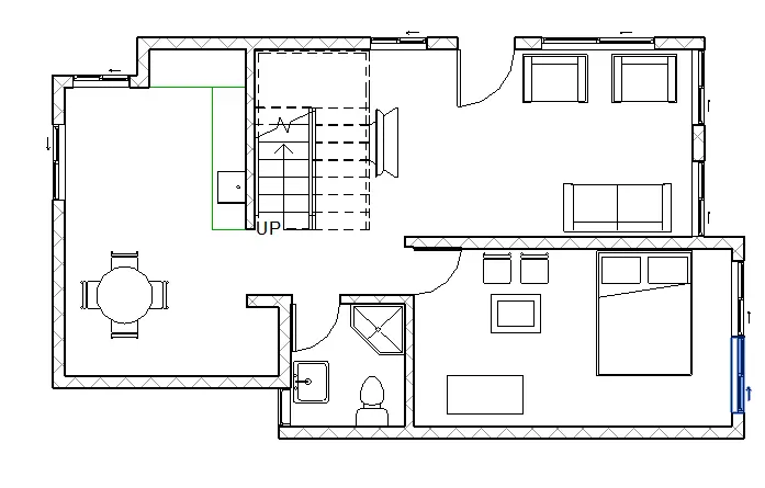
- In the floor plan select the Architectural components of Doors and Windows.
- Load the furniture and other components from the Load Family from Library for use in the project.
- Select the required door, window size and the require furniture type and size and insert in the layout appropriately
- The orientations can be changed by using Spacebar.
- Below is the conceptual plan with the doors, windows and furniture
- Below is the 3D view of the residential unit created for reference which can be further be provided with the floor details, roof details and ceiling details
CONCLUSION: Thus we have provided the residential model elements such as Door, Window and furniture elements into conceptual layout of the residential unit created in previous task by inserting from the library to model. The project is saved for further use.