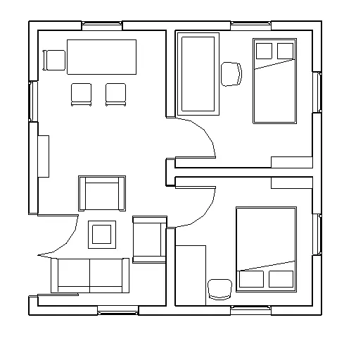
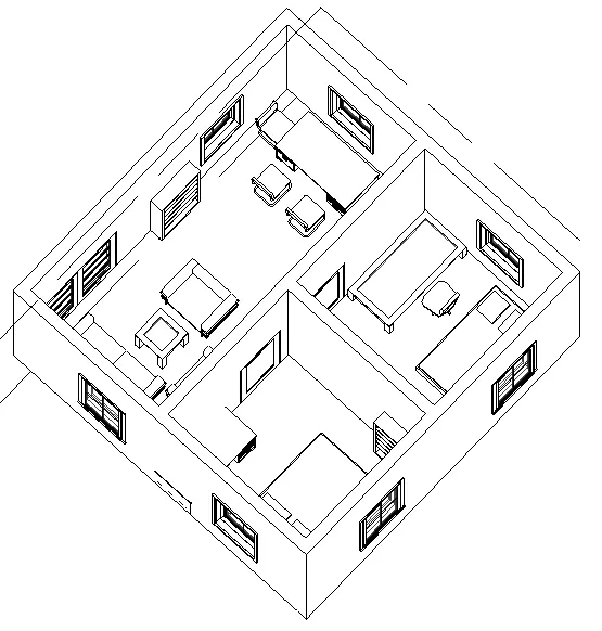
Creating Levels, Grids, Layout and model elements for a residential unit using REVIT
1) The Building Information Modeling (BIM) is an intelligent, 3D model-based process that is the foundation of digital transformation. Civil engineers can create and manage all the information surrounding design assets ensuring improved collaboration, shared data, and project delivery that is on time and on budget. Infrastructure projects today have become more complex. Implementing BIM facilitates project team collaboration; reducing errors, increasing cost predictability, and improving understanding.
Features of BIM are:-
- Easy access to information: BIM is a physical representation of the physical and functional characteristics of the building process, that provides every minute detail of the project. Every stakeholder makes their discipline-specific input to make it a comprehensive shared information resource about the structure. One can easily access the right information at the right time that provides a reliable basis for decision making during a structure’s entire lifecycle.
- Making the process more extensive: CAD software enable users to work accurately in 3 dimensions- length, breadth and depth. However, BIM Modeling servicesproviders are allowed to work in five dimensions, time and cost being the additional dimensions. They are thus able to produce accurate cost and material estimates and precise time schedules of the project even as the design is being developed.
- More comprehensive overview of the project: BIM models not only present 3D geometric view of the structure, they provide a more comprehensive overview of the entire building process. It covers every component of this process from geometrical aspect of the design to spatial relationships, from light analysis to provision of various services, from topographical information to quantities or properties of building components, and so on.
- Lifelike views: BIM design tools allow you to obtain various views from a building model and produce high-quality, accurate drawings. These views are based on a single definition of each object and thus gives a more realistic and accurate idea of the final structure.
Benefits of using BIM over 2D CAD tools are:-
- BIM could save time by an ease of modification: In CAD each part of the project takes place individually as separate drawings like cross sections, layout etc. There is a lack of correlation between them, meaning any change will have to be done manually across all drawings. In BIM on the other hand by optimizing the geometry of one profile we can see the concomitant effect on the other related elements and make the required changes. Moreover, parametric coding in BIM combined with 3D design application means that the designer can automate repetitive design tasks and save time. For instance: with Dynamo Script the designer can define the parameters of the outer wall whose dimensions stay static throughout the project.
-
Increased Project consistency due to enhanced visualization: Generally, in a project the area is large and its aspects complicated. With 2D Drawings, there is a significant amount of imagination required in order to visualize the end project and make sure that it is consistent amongst all stakeholders of the project. The bill of quantities conveyed through CAD Drawings may have significant deviations. It leads to on-site issues such as ordering less or more quantities of materials. While a BIM model is generally made taking into account all crucial information required during the life cycle of the project. The data-rich BIM model allows the right quantity of materials and cost as well as reduces on-site modifications. Moreover, BIM software like Revit can also work in association with modern VR and AR technology. By combining Revit BIM Services with simulation tools the project can be viewed as it is supposed to be, making it possible to appropriately communicate the client’s vision.
-
BIM allows to accurately detecting clashes: In 2D CAD all disciplines i.e. architecture; structure and MEP have their various drawings. Though these drawings may be accurate in their own right but when put together on site this can lead to a multidisciplinary clash. In CAD to detect clash ideally the drawings are put in layers of different colors and then visually compared on the computer screen. Since the collision is examined in 2D it has no depth, and clash detection capacity becomes limited to the engineer’s ability to envision the final project. In BIM all multidisciplinary models are combined in one model making it possible to detect any clashes right at the planning stage. It can identify all types of clashes from hard to soft to even workflow clash. Moreover, with the help of the clash detection tools like Navisworks, required tolerance can be set thus saving time, money and reducing waste and effort.
-
BIM can increase profit margins: As stated above, CAD increases the potential for human error mainly due to the problem of data continuity. The data needs to be checked frequently and the revisions could take time all of which leads to increased man hours. One small revision in CAD leads to a domino effect of changes, as the same revision needs to be changed in all related areas of floor plans, elevations, sections etc. Moreover, errors don’t just end up costing in time it also translates to waste of resources, extended labour costs to make the required variations etc. all of which ultimately make the project more effective. BIM firstly becomes cost effective by utilizing smaller technical teams who handle large amount of data and work. It also means lesser scope of miscommunication and errors directly saving time and money. Since the drawings are extracted from 3D geometry, any change done in the main 3D model, makes subsequent changes in all drawings. Moreover, 4D and 5D dimensions of BIM allows for proper cost estimation and scheduling – making it possible to get maximum results by using pertinent amount of time, effort and materials only.
2)
Category: It is the revit element that controls the organization, Visibility, Graphical representation and scheduling options of families within the project. It is like a head.
Family: It is the group of 2D or 3D information that serves to represent a discrete building or documentation element in a project. It also defines parametrical, graphical and documentation requirement also.
Types: This is a specific representation in a family defined by distinct parametric graphical and documentation characteristics which makes it unique from other types in the family. Once we will get into family then we get the Elements.
Instance: It is the individual representation of a type in the project defined by unique parametric graphical and documentation characteristics makes it unique from other instances in the project.
Now we have to insert the above in the revit model.
PROCEDURE:
- Go to desktop and select the below shown icon.
- Once the icon the selected then the below shown dialogue box will appear.
- Here click NEW option which is present in upper left hand side.
- The above dialogue option will appear.
- Here select the template file and type of project and click OK button.
- Then the drawing sheet will appear with different options to draw and with certain levels.
- Once the drawing sheet is opened now we have to save the drawing.
- Save the drawing using the mentioned steps in previous question.
- Go to architectural toolbar and select wall there are two types of wall.
- Load bearing and Architectural wall select as wanted.
- Select the required type of wall and different options will appear in the toolbar.
- Using those options we can do several editings in wall and different shapes also.
- Here in draw option we can draw the wall in different shapes and size.
- Here we will choose ine option to draw a wall.
- Here we have to select the height of wall.
- Alignment of wall in Location line. Offset if any needed.
- After selecting all the dimensions and doing all the editings now draw the line as required.
- Click anywhere in the drawing sheet and take the curzer horizontally and type 45' the wall will be displayed as shown.
- Now take the cursor in 90degree and type the reading or length as mentioned.
- Carry the same steps and complete the wall in four sides.
- After completing the drawing now add the family.

- Go to insert and there will be a option as load family there we can add the or there is also another way as shown below.
- Go to door menu and the ribbon tab will change like shown below.

- The above show tab will appear then there select the load family option.
- As soon as we select the load family the below tab will appear.
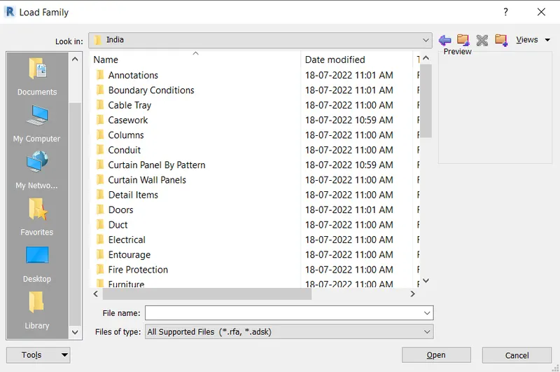
- Here select the target location where the family are located or saved then open the required file and select the required door. The above shown files are called as CATEGORY.
- Once we select the required category then we go to families.
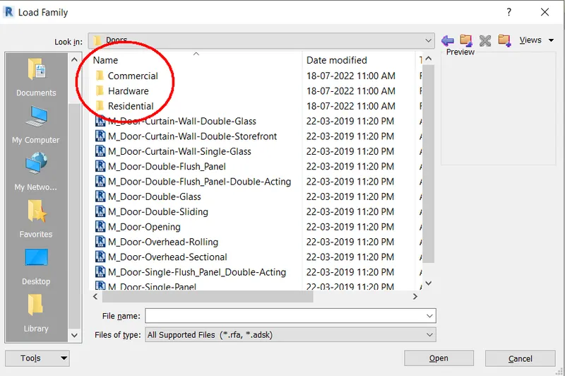
- The above marked things are called as FAMILY inside that there are elements.
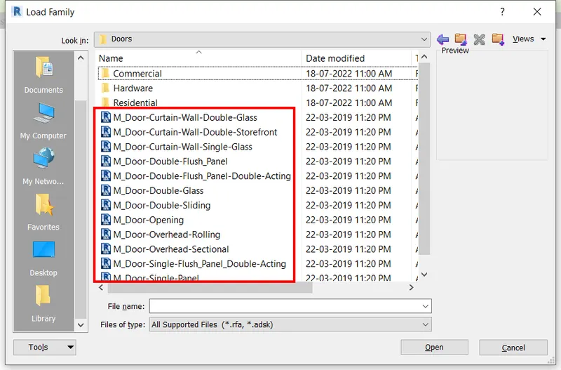
- These are all the elements. From here we have to select the required doors and place it in the revit model.
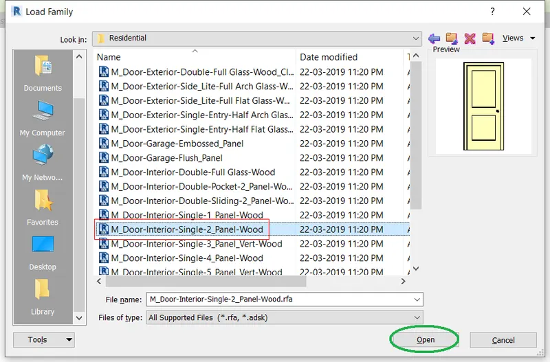
- Next select the open option then we will be directed to another dialogue box where we have to select the size as per our requirement.
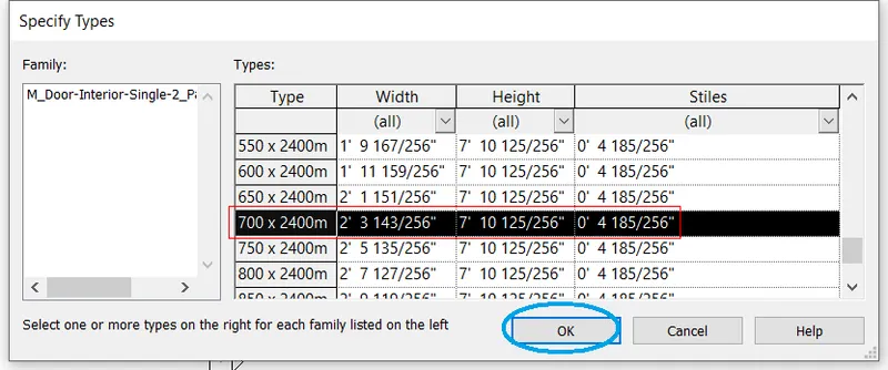
- After selecting the required size of door then we will be directed to the drawing sheet and there we have to place the door as per requirement.
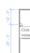
- The same procedure will be carried out for windows.
RESULT:
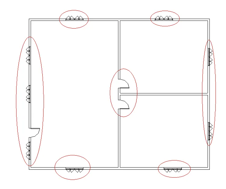
3) AIM: To set up a Project – Open a project file with architectural template. Save the file with appropriate name. Set up the project units to Imperial / Metric based on your convenience of modelling. Complete the project information under Manage tab. Set up the maximum backups for project file to 3.
PROCEDURE:
- Go to desktop and select the below shown icon.

- Once the icon the selected then the below shown dialogue box will appear.
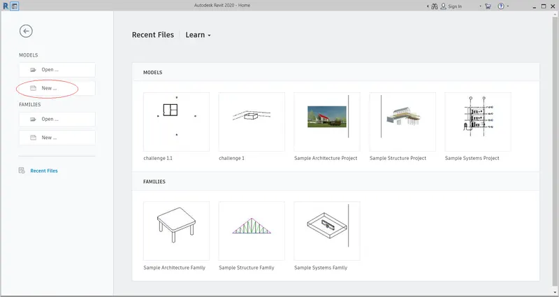
- Here click NEW option which is present in upper left hand side.
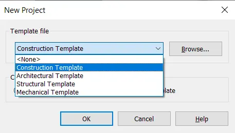
- The above dialogue option will appear.
- Here select the Architectural template file and type of project and click OK button.
- Then the drawing sheet will appear with different options to draw and with certain levels.
- Once the drawing sheet is opened now we have to save the drawing.
- Now go to file menu and select the save option.
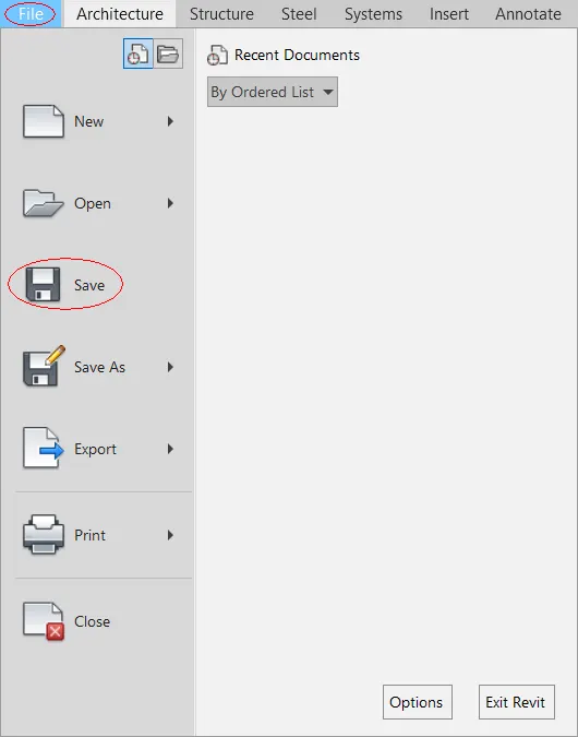
- Now after selecting the save option the another dialogue option will appear.
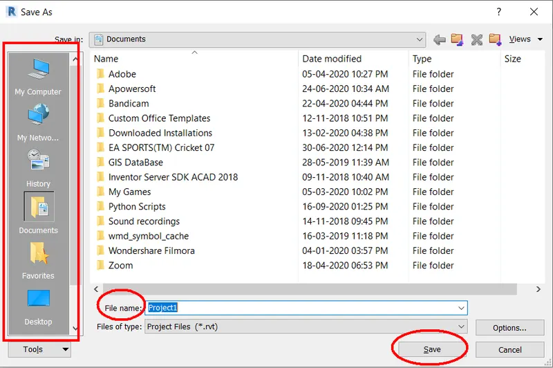
- Here there are several options.
- Select the place where the drawing has to be saved in. Using save in option.
- After selecting the place where the drawing has to be saved then give the name of drawing so that it can be easily identified.
- Once the file naming is done then select the save option then the drawing will be saved.
- Now we have to edit the project information.
- To edit the project settings go to manage menu.
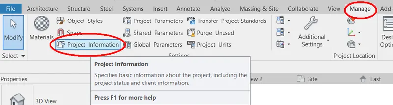
- The option toolbar will appear then go to Project information option.
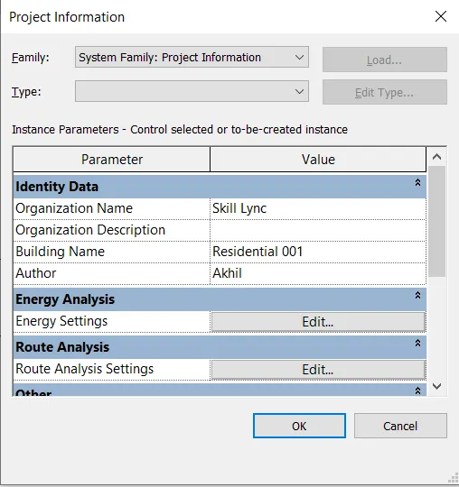
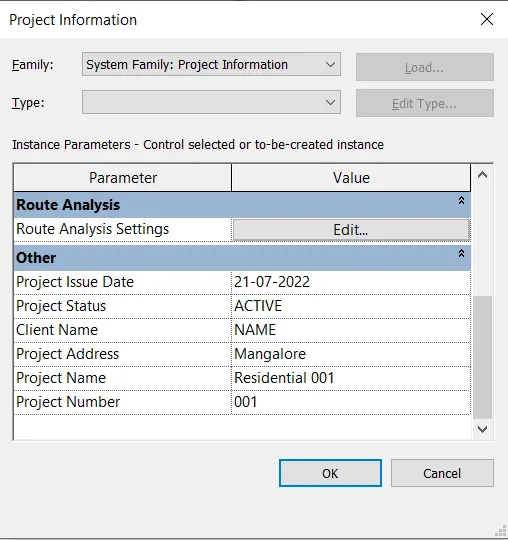
- Once we select the option the above dialogue box will appear.
- Here we edit the items that are mentioned tobe edited.
- Now we have to Set up the maximum backups for project file to 3.
- Now go to file menu and select the save option.
- Now after selecting the save option the another dialogue option will appear.
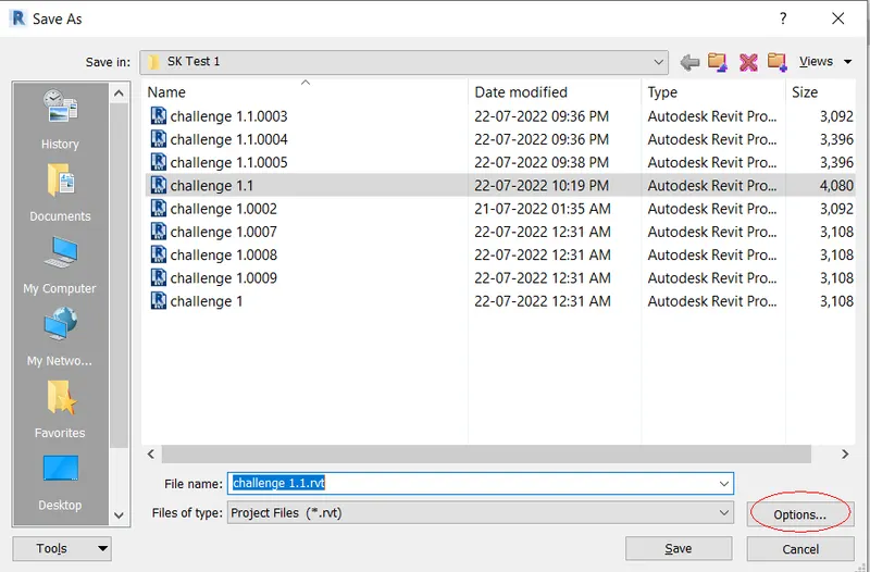
- Go to OPTION selectio and another dialogue box will appear.
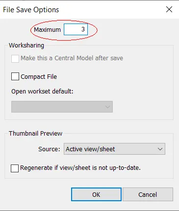
- Here select the Maximum backup upto 3.
- Here the maximum setting can be done till 99 no's.
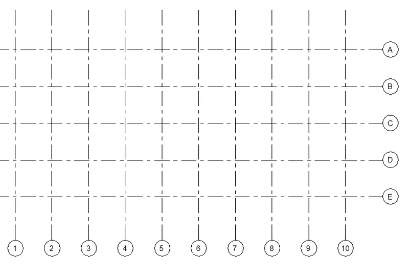
4) AIM: To Levels and Grids in a given distance and mentioned namings.
PROCEDURE:
- Go to desktop and select the below shown icon.
- Once the icon the selected then the below shown dialogue box will appear.
- Here click NEW option which is present in upper left hand side.
- The new dialogue option will appear.
- Here select the template file and type of project and click OK button.
- Then the drawing sheet will appear with different options to draw and with certain levels.
- Once the drawing sheet is opened now we have to save the drawing.
- Save the drawing using the mentioned steps in previous question.
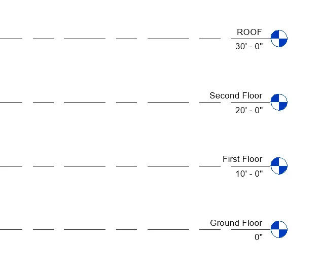
- Go to elevation view to create the levels because in the plan view the levels cannot be created.
- Go to architectural toolbar and select LEVELS option.

- The above options will appear then select the type by which you want to add the levels.
- There are two types, Line and pick line select the convinent one.
- Once the method is selected then give the offset on the levels as mentioned in the question.

- Then select the base level line from where the levels has to be made.
- Next select the recently created level line to create another new level.
- Carry same procedure till mentioned height and name the level as mentioned.
- Once the levels are done now we have to do the Transverse grids as given dimension and naming.
- Again go to Architectural option in toolbar and then select grid option.

- The below shown options will come

- Here there are several options to do the grid so select the line method for once.
- Click the start and end point of the grid line and nest select the pick lines option and input the offset value as mentioned. Here the first line is drawn Horizontally.

- Then select the first drawn line as baseline and create the number of lines as required.
- Once the line is done to make a new one select the previously created line.
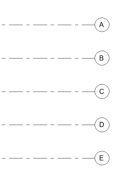
- There will be numbers in the circle edit it to alphabets.
- Double click the numbers and re-write it using required alphabets.
- Next we have to draw the longitudinal grid.
- The steps are all same as done for Transverse grid.
- The change is just to draw the first line vertically.
- The same procedure is followed as for transverse method.
- Here after drawing the first line change the naming because the grid will continue in Alphabetical order.
- Once the first line is edited then all will come in correct required way.
RESULT:

5) AIM: To create a conceptual layout of the residential unit.
PROCEDURE:
- Go to desktop and select the below shown icon.
- Once the icon the selected then the below shown dialogue box will appear.
- Here click NEW option which is present in upper left hand side.
- The above dialogue option will appear.
- Here select the template file and type of project and click OK button.
- Then the drawing sheet will appear with different options to draw and with certain levels.
- Once the drawing sheet is opened now we have to save the drawing.
- Save the drawing using the mentioned steps in previous question.
- Go to architectural toolbar and select wall there are two types of wall.
- Load bearing and Architectural wall select as wanted.
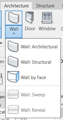
- Select the required type of wall and different options will appear in the toolbar.
- Using those options we can do several editings in wall and different shapes also.

- Here in draw option we can draw the wall in different shapes and size.
- Here we will choose ine option to draw a wall.
- Here we have to select the height of wall.
- Alignment of wall in Location line. Offset if any needed.
- After selecting all the dimensions and doing all the editings now draw the line as required.
- Click anywhere in the drawing sheet and take the curzer horizontally and type 20' the wall will be displayed as shown.
- Now take the cursor in 90degree and type the reading or length as mentioned.
- Carry the same steps and complete the wall in four sides.
- By this way complete the outer wall and next using offset command draw the interior walls.
- Specify the required room size and do the offset work.
- Keep the wall location line as per requirement.
- Specify the height as required.
RESULT:
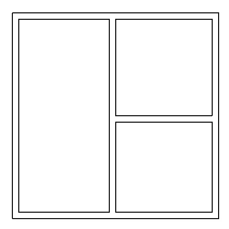
6) AIM: To in the layout created draft the level of details you are planning to include – Dimensions of room, components you plan to add in the residential unit.
PROCEDURE:
- Go to desktop and select the below shown icon.
- Once the icon the selected then the below shown dialogue box will appear.
- Here click NEW option which is present in upper left hand side.
- The above dialogue option will appear.
- Here select the template file and type of project and click OK button.
- Then the drawing sheet will appear with different options to draw and with certain levels.
- Once the drawing sheet is opened now we have to save the drawing.
- Save the drawing using the mentioned steps in previous question.
- Go to architectural toolbar and select wall there are two types of wall.
- Load bearing and Architectural wall select as wanted.
- Select the required type of wall and different options will appear in the toolbar.
- Using those options we can do several editings in wall and different shapes also.
- Here in draw option we can draw the wall in different shapes and size.
- Here we will choose ine option to draw a wall.
- Here we have to select the height of wall.
- Alignment of wall in Location line. Offset if any needed.
- After selecting all the dimensions and doing all the editings now draw the line as required.
- Click anywhere in the drawing sheet and take the curzer horizontally and type 20' the wall will be displayed as shown.
- Now take the cursor in 90degree and type the reading or length as mentioned.
- Carry the same steps and complete the wall in four sides.
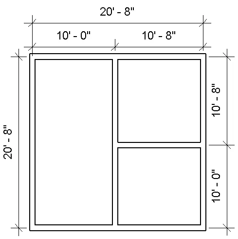
- By this way complete the outer wall and next using offset command draw the interior walls.
- Specify the required room size and do the offset work.
- To do the dimension work go to Annotate option.
- Here we have to do the dimensioning so take the drawing that has been done in question 3.
- Go to Annotate tab and the below mentioned toolbar will appear.
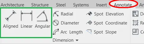
- Now here select the type of dimensioning you want.
- Here there are several options for dimensioning. Here we can do the dimensioning of radius, Diameter etc.
- Now here we are selecting the LINEAR dimensioning because the drawing is aligned linerally.
- Now go near drawing and click the start point of the dimension.
- Next click on the other side of the drawing which is in right angle.
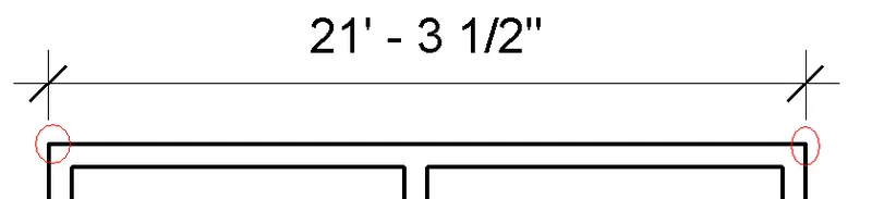
- After that take the curser in upward direction till the required height then place it.
- Cary the same steps for all the remaning side of the wall.
- Here we can use either Aligned or Linear dimensioning.
- We can do several dimensioning here.
RESULT:
7) AIM: To add the elements like door, window, chair, bed etc from the family for the above drawing.
PROCEDURE:
- Go to desktop and select the below shown icon.
- Once the icon the selected then the below shown dialogue box will appear.
- Here click NEW option which is present in upper left hand side.
- The above dialogue option will appear.
- Here select the template file and type of project and click OK button.
- Then the drawing sheet will appear with different options to draw and with certain levels.
- Once the drawing sheet is opened now we have to save the drawing.
- Save the drawing using the mentioned steps in previous question.
- Go to architectural toolbar and select wall there are two types of wall.
- Load bearing and Architectural wall select as wanted.
- Select the required type of wall and different options will appear in the toolbar.
- Using those options we can do several editings in wall and different shapes also.
- Here in draw option we can draw the wall in different shapes and size.
- Here we will choose ine option to draw a wall.
- Here we have to select the height of wall.
- Alignment of wall in Location line. Offset if any needed.
- After selecting all the dimensions and doing all the editings now draw the line as required.
- Click anywhere in the drawing sheet and take the curzer horizontally and type 20' the wall will be displayed as shown.
- Now take the cursor in 90degree and type the reading or length as mentioned.
- Carry the same steps and complete the wall in four sides.
- By this way complete the outer wall and next using offset command draw the interior walls.
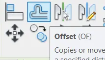
- Specify the required room size and do the offset work.
- After completing the drawing now add the family.
- Go to insert and there will be a option as load family there we can add the or there is also another way as shown below.
- Go to door menu and the ribbon tab will change like shown below.
- The above show tab will appear then there select the load family option.
- As soon as we select the load family the below tab will appear.
- Here select the target location where the family are located or saved then open the required file and select the required door. The above shown files are called as CATEGORY.
- Once we select the required category then we go to families.
- Here we are going to select the door for the house.
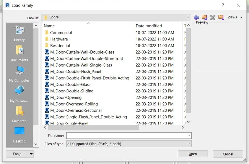
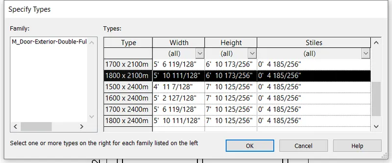
- From the above we will select residential and select the required door and fix it in the wall as per required.
- Same think is done for window and other things.
- For bed, chair etc we have to select the component in the properties bar.
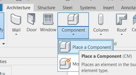
- To place the above mentioned go to component and select place component.
- Follow the same old basic steps and do the designing.
- Then select the design and size as per required and place it where ever required.
- All the mentioned items are applied using the method explained above in the previous questions.
RESULT: