Creating Levels, Grids, Layout and model elements for a residential unit using REVIT
1) What is BIM? Summarize the features of BIM and benefits of using BIM over 2D CAD tools.
ANSWER-
BIM: Building Information Modelling is design and documentation system that suppose to the design drawings and schedules required for the building project. Revit building elements are three types,
- View Elements
- Model Elements
- Annotate Elements
- Annotation Elements
- Datum Elements
Building Information Modelling is holistic process of creating and managing information for a built asset. Based on intelligent model unable to buy cloud platform BIM integration structured, multidisciplinary data to produce a digital representation of an asset across its life cycle from planning and design to construction operations. BIM is a virtual representation of a physical and functional characteristics of facility from inception onwards, as such it serves as a shared information repository for collaboration throughout facilities life cycle. BIM consist mainly of 3D modelling concepts in addition of information, database technology and interpolate software in a desktop computer environment that architect’s engineers and contractors can be used to design a facility and simulate construction, so this technology allows members of the project team to generate a virtual model the structure and all of its system in a 3D and to be able to share that information with each other.
Features of BIM: there are multiple features of BIM available in the beam software
- Easy access to information: It is a physical representation of the both physical and functional characteristics of the building process that provides very minute detail of the project
- Making the process more expressive: CAB software allows the user to work accurately in three dimensions that is length, breadth and depth however BIM modelling services providers allowed to work in five dimensions that is time and cost apart from length, breadth and depth they are able to produce accurate cost and material estimates precise time schedules of the project even as the design is being developed.
- Comprehensive view of the project: BIM model not only presence the 3D geometric mean of the structure they provide a more comprehensive overview of the entire building process, actually it covers every component of this process from geometrical aspects of the design to spatial relationship from light analysis to provision of various services from topographical information’s to quantities on properties and so on.
Benefits of BIM:
- Complete Representation: complete representation of a building design it takes more than the building 4 components into account for example BIM allows you to design electrical and HVAC systems as well as the building itself.
- Instant Updates: BIM allows you to provide instant updates of all the components.
- Time Constraint: BIM model will allow you to prefabricate important components ahead of time you won’t have to adjust them based on the building design insert such components are part of the initial design.
- Resource Tracking: the models you give to your clients update constantly as you work on your projects your clients can check in anytime which leads to quick approval for milestone and more efficient project development. resource tracking is there actually a key component of BIM models you will be able to figure out how much of each resource is you need during design stage this improves the flow and efficiency of constructions
2) Understand the concept of Categories, Families, Elements, Instances in Revit. Go to Insert Tab, choose a category. Pick a family and element. Understand the instances and insert it to Revit model
ANSWER
- Category: it is one of the Revit element hierarchies, it controls the organization, disability, the graphical representations and scheduling options of families within the project.
- Family: family is a group of 2D or 3D information that serves to represent discrete building or documentation element in the project. it defines parametrical, graphical and documentation requirement also.
- Type Option: type specific representation in a family defined by distinct parameter, graphical documentation characteristics which makes its unique from other types in the family
- Elements or Instances: it is an individual representation of time in the project, defined by unique parametric graphical and documentation characteristics which makes it unique from other instances in the project
PROCEDURE:
STEP 1) INSERT ELEMENT
- Launch the Revit software
- Open last week challenge 01 Architectural Drawing
- Go to the Insert View and click on the Load Family or
- Go to the Architecture tab and drop down the Component option

- Click on to the Place a Component
- A new tab will open Modify| Place Component

- Select Load family option from Mode
- It will open a dialog box for CATEGORY
- Select the desire category like door, Window, etc.
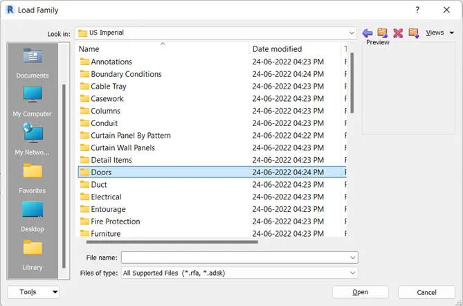
- After selected category, Select the TYPES like Commercial, Hardware, Residential
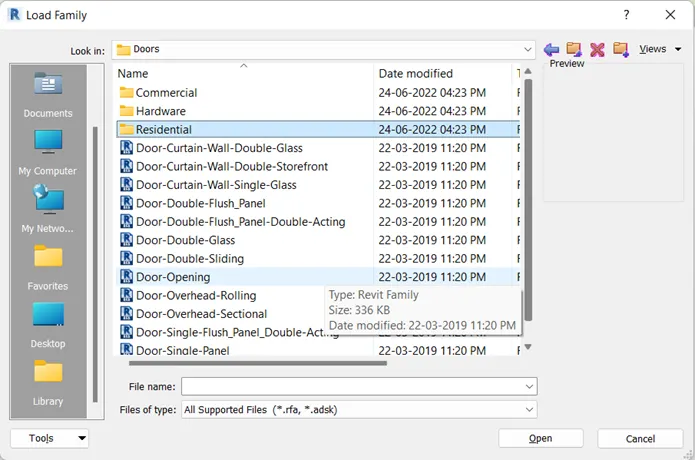
- After that we have multiple ELEMENTS
- Select the door as required
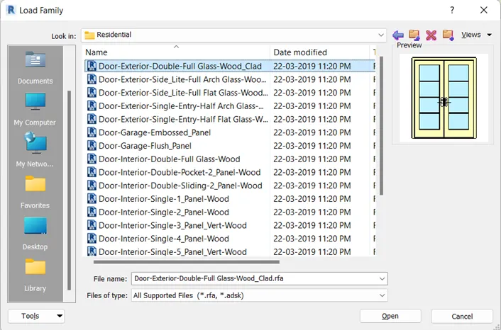
- Select the specific size of door
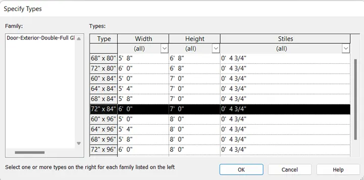
- Insert the component at desire location in drawing
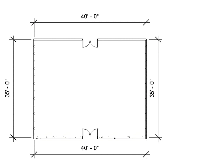
RESULT:
After following all the step and procedure, got the result
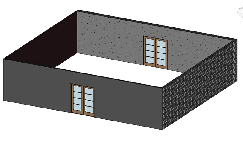
3) Setting up a Project – Open a project file with architectural template. Save the file with appropriate name. Set up the project units to Imperial / Metric based on your convenience of modelling. Complete the project information under Manage tab. Set up the maximum backups for project file to 3
AIM:
Setup a project in architectural template
INTRODUCTION:
Setting up a project with an architectural template, save the file with appropriate name, setup the units, complete the project information and set the backup of project file
PROCEDURE:
STEP 1) CREATE NEW PROJECT
- Launch the Revit software
- Click on File>New>Project
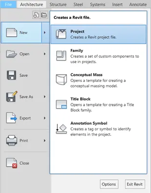
- Change the templet as Architectural templet and click OK
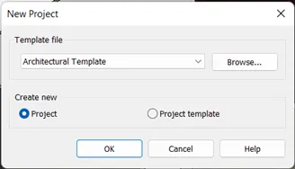
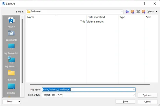
- Save the file as appropriate name à Arch_Drawing_chanllenge2
STEP 2) UNIT SET
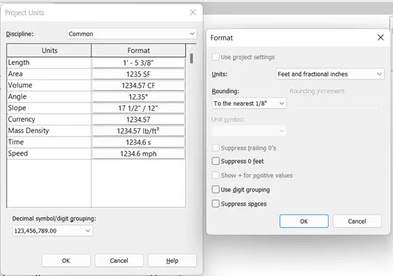
- To set the project unit type UN
- Click on Length Format
- Select feet and fractional inches from units
- Select to the nearest 1/8” from rounding then OK
STEP 3) BACKUP
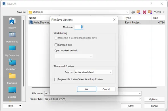
- Click on File>Save as>Options>maximum number of backup file>provide as>click on OK and then save
STEP 4) PROJECT INFORMATION
- For completing the project information
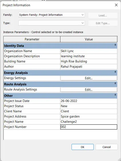
- Open MANAGE tab
- Select Project Information

- Project information dialog box will show
- Provide the basic information of current project
- Like identify data and other
RESULT:
Basic setting and information of a new project is completed after following above steps
4) Understand the concept of Levels and Grids. Follow the naming and conventions. Create the following Levels: ( Convert to metric equivalents if metric is your units)
Ground Floor @ 0’
First Floor @ 10’
Second Floor @ 20’
Roof @ 30
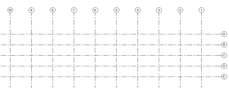
Grids Transverse Grids A, B,C,D, E @ 10’ spacing
Longitudinal Grids from 1 to 10 @ 20’ spacing
AIM:
Create the Levels and understanding about Levels and Grids
INTRODUCTION:
The concept of levels and grids are understood and following name and order convention
PROCEDURE:
STEP 1) OPEN MODEL
- Launch the Revit software
- Click on open and select previously created drawing as Arch_Drawing_chanllenge2
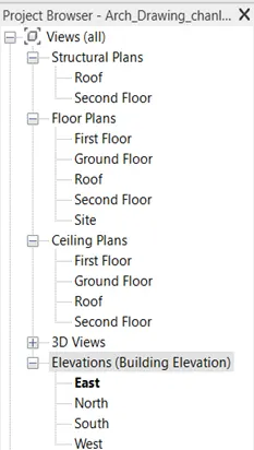
STEP 2) CREATE LEVELS
- In the project browser expand the Elevation View and select any one direction for Level
- Change the Name of level 1 as Ground Floor
- Level 2 as First Floor
- Add 2 more level at 10’ offset from the Architecture tab (datum panel) à select Level

- In draw panel select Pick Line and enter the Offset value as 10’

- Select top most level and click for add the new levels
- Rename both the level as Second Floor and Roof Respectively
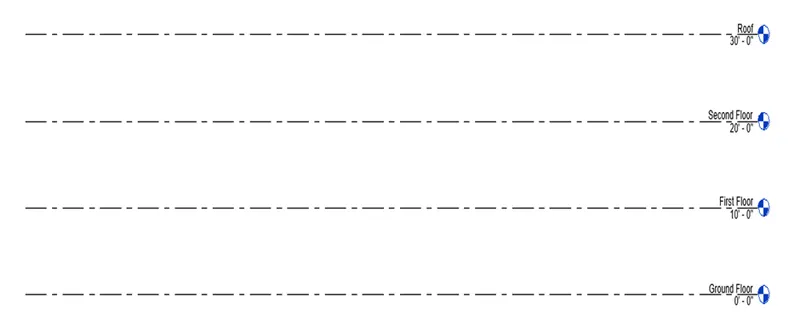
STEP 3) LONGITUDINAL GRIDS
- Close the EAST tab
- In the architectural tab>datum>grids

- Create a line for longitudinal grid Esc
- Select Pick from draw tool
- Set offset 20’

- Click on grid line and move cursor left side for 9 time
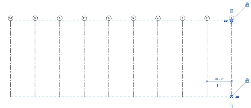
STEP 4) TRANSVERSE GRID
- Similarly, In the architectural tab>datum>grids
- Create a line for transverse grid Esc
- Select Pick from draw tool
- Set offset 10’
- Click on created transverse grid line and move cursor down side for 4 times Esc
- Rename the grids as A, B, C, D, E
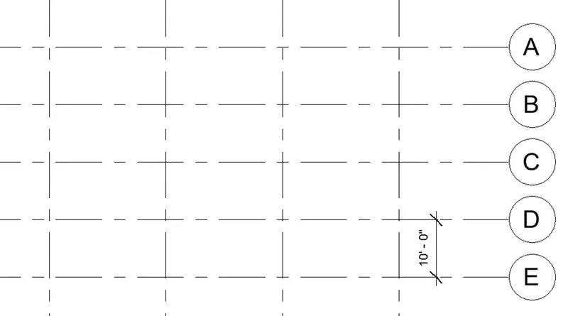
RESULT:
Following the above procedure to obtain the final result
5) 3D modelling of residential unit – From looking at your house / or a place you aspire. Create a conceptual layout of the residential unit. You can measure using a tape or you can access your residential plan to create a similar layout.
AIM:
Created a conceptual layout and 3D model of residential unit
INTRODUCTION:
The conceptual layout and 3D model of residential unit of my house is created in Revit. The procedure is shown and explained step by step.
PROCEDURE:
STEP 1) OPEN MODEL
- Launch the Revit software
- Click on open and select previously created drawing as Arch_Drawing_chanllenge2
STEP 2) CREATE CONCEPTUAL LAYOUT
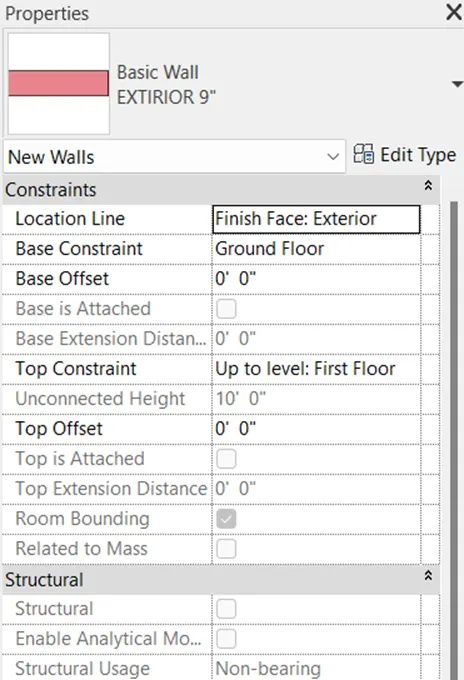
- In the Architectural Tab select WALL
- Change height as First Floor
- Location line change as Finish Face Exterior

- Change wall property from Properties Broswer
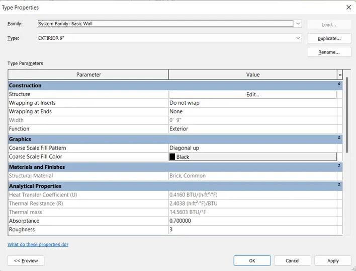
- Select Generic 5” wall then click Edit Type
- Make a duplicate of this wall and rename as EXTIRIOR 9”
- Change the Width of wall from Structure Edit
- Provide thickness as 9” then click OK
- After that draw the walls
STEP 3) ANOTATION
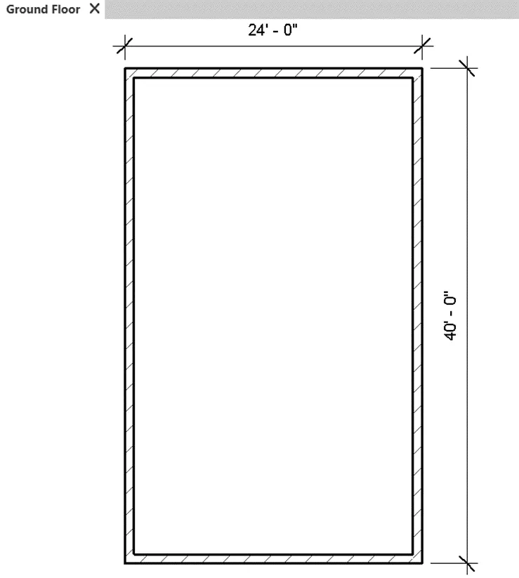
- Go to Annotate Tab>Linear

- Click on the finish exterior wall to show the dimension
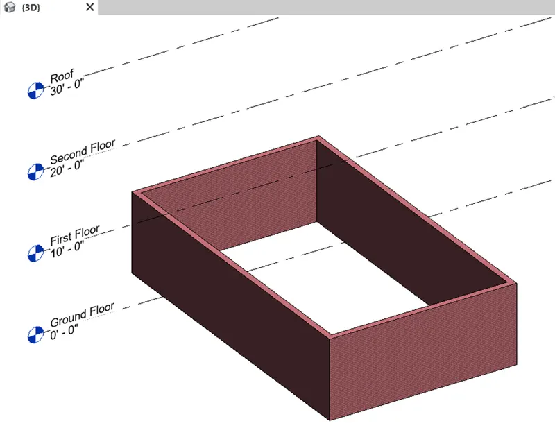
STEP 4) 3D MODEL
Go to viewà drop down the 3D viewàclick on the default 3D vew
RESULT:
After following above procedure, we completed the conceptual layout and 3D residential model
6) In the layout created draft the level of details you are planning to include – Dimensions of room, components you plan to add in the residential unit.
AIM:
Draft the level of details such as dimension of room, component
INTRODUCTION:
Created interior walls in the last conceptual layout and provide dimension of room. The procedure is shown and explained step by step.
PROCEDURE:
STEP 1) OPEN MODEL
- Launch the Revit software
- Click on open and select previously created drawing as Arch_Drawing_chanllenge2
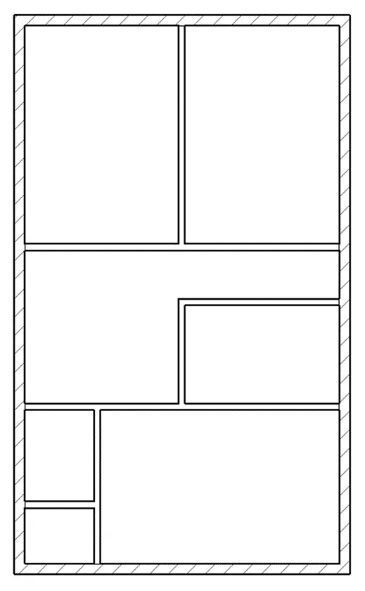
STEP 2) CREATE WALL
- In the Architectural Tab select WALL
- Location line change as Finish Face Interior
- Change wall property from Properties Broswer
- Select interior 5 ½ ” partition wall
- After that create the walls
STEP 2) ANNOTATION
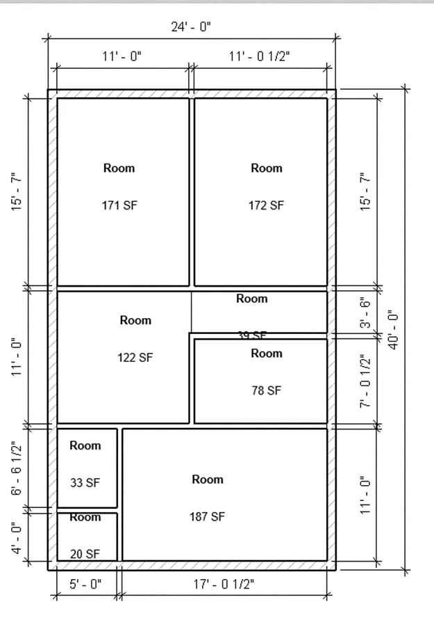
- Go to Annotate TabàLinear
- Click on the finish exterior & interior wall to show the dimension
- Go to Architecture Tab>Room from Rooms and Areas

RESULT:
After following above procedure, created the dimension of the room, components.
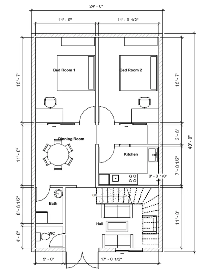
7) Identify the residential model elements such as Door, Windows, Tables, Chair, Couch, Bed, Lamps from the library and insert them to the model . Save the project for use
for Assignment 3
AIM:
Identified the residential model of door window table chair etc, insert from the library
INTRODUCTION:
Elements are inserted in the residential model from the library to identify the residential model and save for next challenge. The procedure is shown and explained step by step.
PROCEDURE:
STEP 1) OPEN MODEL
- Launch the Revit software
- Click on open and select previously created drawing as Arch_Drawing_chanllenge2
STEP 2) INSERT ELEMENTS
- In the INSERT tab select Load Family form panel
- Select residential door, window
- Select furniture, Fixtures etc.
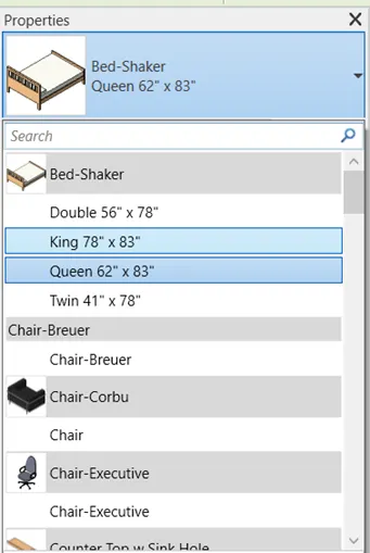
- After the loading families open properties browser
- Select to pick elements and press space button to rotate item accordingly
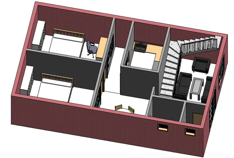
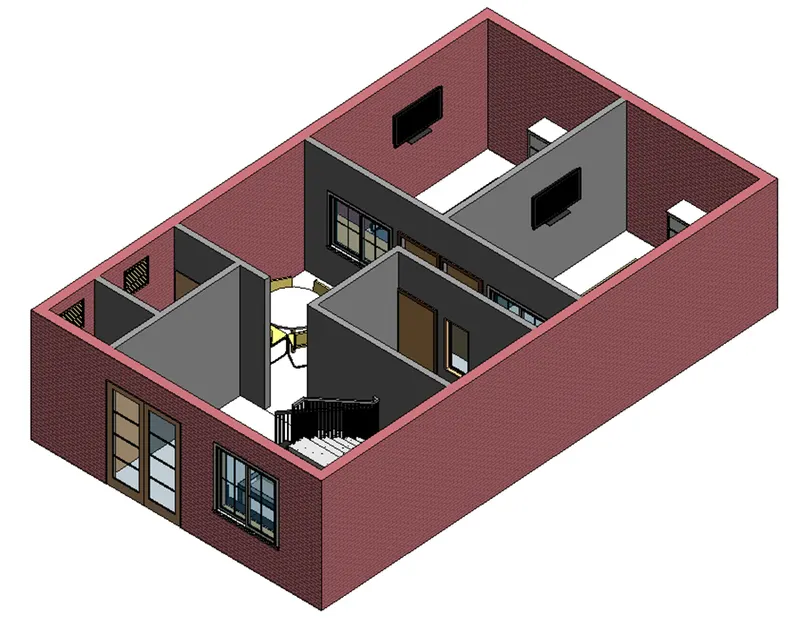
STEP 3) ELEMENTS in 3D MODEL
RESULT:
After following above procedure, elements are inserted from library and save for next challenge.