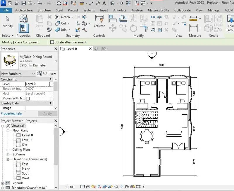
Creating Levels, Grids, Layout and model elements for a residential unit using REVIT
1) What is BIM? Summarize the features of BIM and benefits of using BIM over 2D CAD tools
ans. it is a visual reprasentation of a the physical and functional chacterstics of a faciliting from inception onwards as such it serves a shared information reprasenting for collaboration througth a facuilitys life cycle.
features of bim:
- easy access to information
- making the process more expressive
- comprehenssive view of the project
benfits of BIM.
- Complee reprasentation of building design
- instant updats of all the constrations
- time constraint
- resource tracking
2) Understand the concept of Categories, Families, Elements, Instances in Revit. Go to Insert Tab, choose a category. Pick a family and element. Understand the instances and insert it to Revit model
ANS:
catagory : it controls the organization disibulity graphical reprasentations and scheduling options of families with in the project
family : a family is a group of 2D & 3d information that surver to reprasentation of decrite building or documentation elemet in the project. It defines phermetrical graphical,and documentation requirement also.
Type: Type is specific reprasentation parameter graphical and documentation charectertics which makes it unique from other in the family.
Instances in revit: instances on indiviual reprasentation of a type in the project defines by unique parametric graphcal documentation charecterstics which makes here unique from other instances from project.
AIM: Go to Insert Tab, choose a category. Pick a family and element. Understand the instances and insert it to Revit model
PROCEDURE:
- select any element from tools like doors after that we get another tool window is opened in that last 2nd we get a icon load family icon
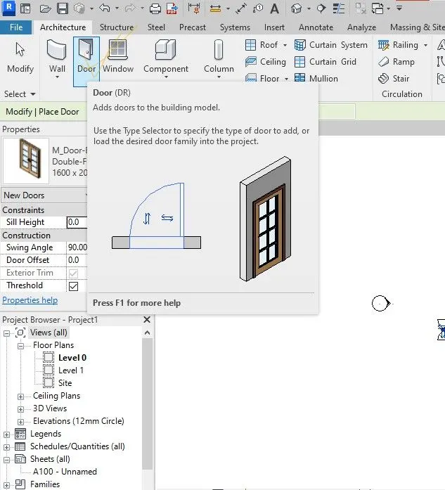
- select load family icon we get a pop-up window of load family after we got a so many options regarding our purpose or utility.

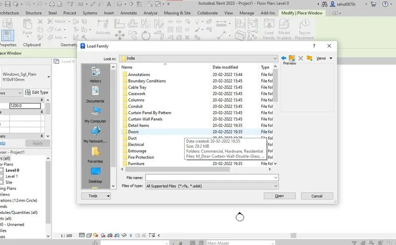
- select type or family or catagiry and instances of revit we select
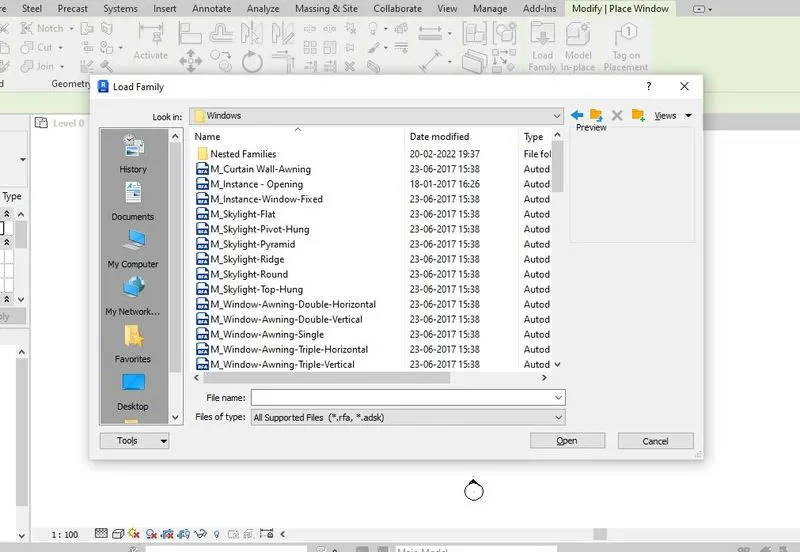
- select any eleemt for our requirement and place(insert) where ever we want
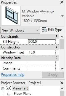
- that element appears property brower and it enable to cutomize the elemet.
3) Setting up a Project – Open a project file with architectural template. Save the file with appropriate name. Set up the project units to Imperial / Metric based on your convenience of modelling. Complete the project information under Manage tab. Set up the maximum backups for project file to 3
ANS:
- Open revit application by clicking desktop icon
- when we get home page of revit we got new icon click on that
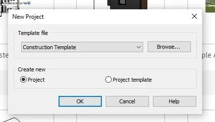
- select require template on that rolling arrow buttion.
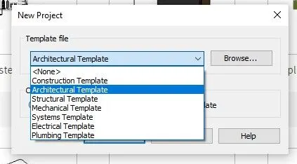
- select architectural template click ok.
- we get a working screen is opened with architectural commands require in design
- now we have to click on the file tab in top left corner select save as file
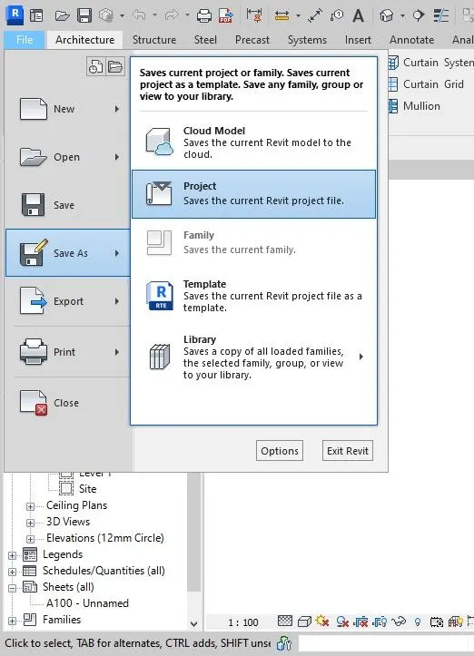
- select project we get destination window opened for where we have to save
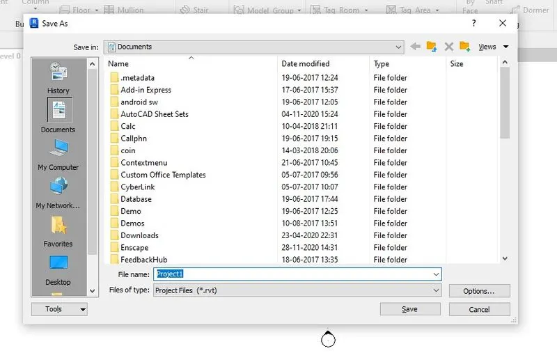
- select proper location for save the file.
- now we have to go and select mange tab on riddion

- select project information tool in mange tab
- we get pop-up window for enter details to fill on that window
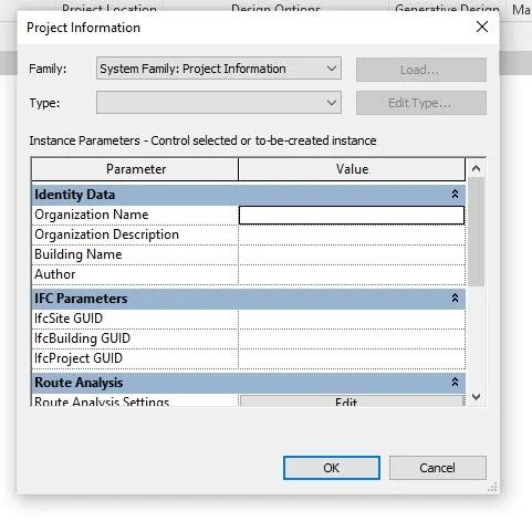
- in that project information window we have to fill the all information related the project which reflect information in print layout template tab.
- now we have to click on the file tab in top left corner select save as file
- select project we get destination window opened for where we have to save
-
- select the options command in save as window. we get a another pop-up window for file save options
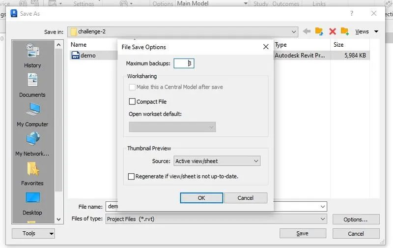
- in that we change the number of backups in require numbers
- select enter to save information.
- now we change the dimentions from mange < select project units < change the dimentions from there
-
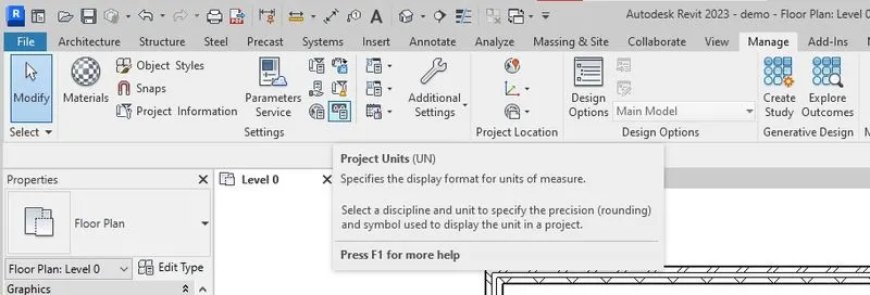
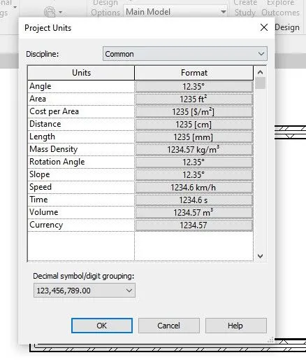
- click ok to save the changes to metric units.
4)AIM: Understand the concept of Levels and Grids. Follow the naming and conventions. Create the following Levels: ( Convert to metric equivalents if metric is your units)
Ground Floor @ 0’
First Floor @ 10’
Second Floor @ 20’
Roof @ 30’
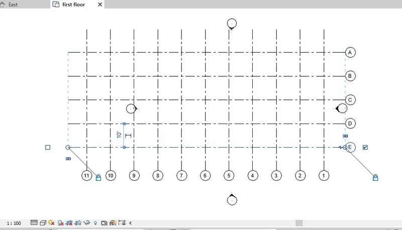
Grids Transverse Grids A, B,C,D, E @ 10’ spacing
Longitudinal Grids from 1 to 10 @ 20’ spacing
PROCEDURE:
- open new file in revit with architecture template and tools
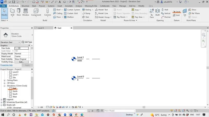
- select elevation in project brower then the level tool is enable in arechiture tab to place
- we get defult 2 levels are given by template.
- after we select level tool that is places in right upper corner in tools we another editing options contains
- 1st one is line command and another ones is pic-line command
- if we select line command we select 1st point and 2nd point manuwally
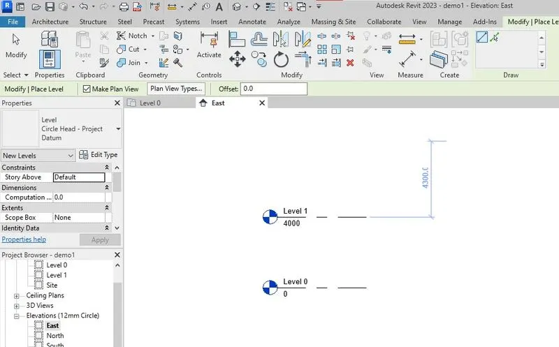
- if we select pic-line command we enter the offset
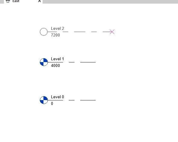
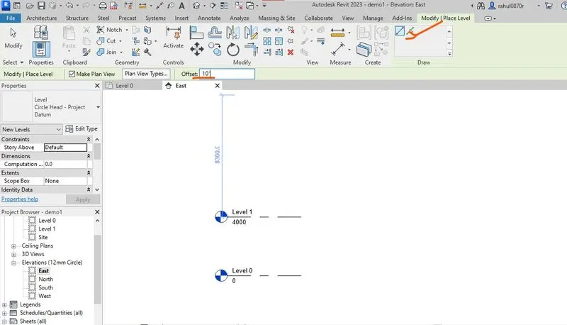
- now we can change level names by click on that to select to edit the level
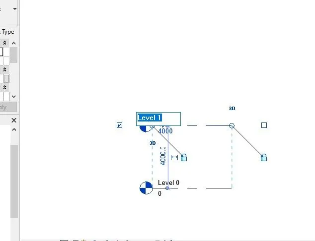
- enter name what we want to mention in level we edit
- now we select the project browcer level in that select grid in that tools right upper corner

- now we get another 4 edit option can display in ribbion tab for that can help us to place line,arc and pic-line command
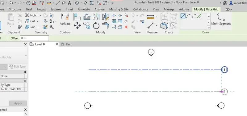
- we select the line command in that we can manuwally select the points we require
- then we select the pic-line command to we enter offset length select line automaticaly grid placed in what offset length we mention before
- if want to edit names of grids to select the text box it getting edit we select manner we want
RESULTS:
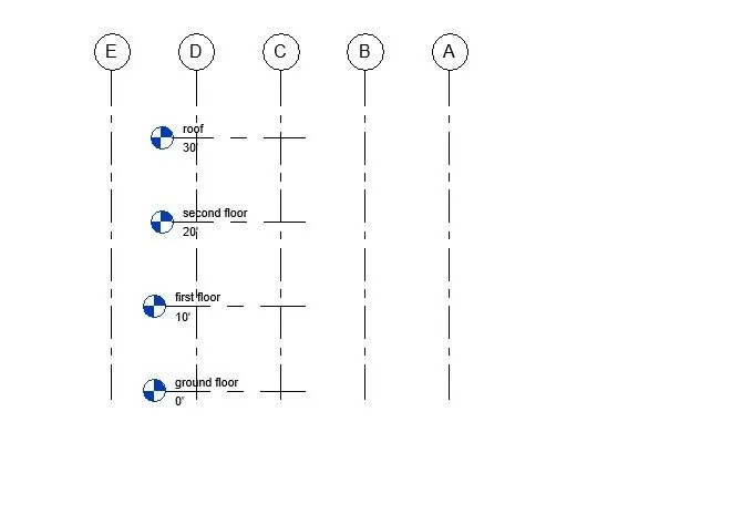
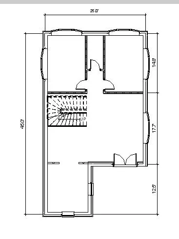
5)AIM: 3D modelling of residential unit – From looking at your house / or a place you aspire. Create a conceptual layout of the residential unit. You can measure using a tape or
you can access your residential plan to create a similar layout.
PROCEDURE:
- Open new file in revit
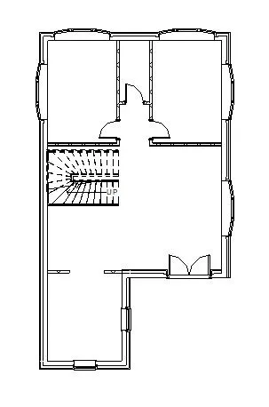
- select wall tool from riddion select 1st point and select 2nd poin 25' length
- select external wall and vertical line length of 45' lenght
- now select the interiar wall offset 14' the horizontal exterior wall
- now again offset the offset 17' the interior wall in horizontal
- add windows to select windows in ribion
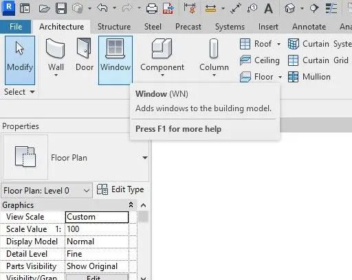
- after we get a another tools unit appear select load family on that tools unit

- we get reference family element appered we should select which is suitable for that project.
RESUILTS:
AIM6:In the layout created draft the level of details you are planning to include – Dimensions of room, components you plan to add in the residential unit.
PROCEDURE:
- open orious design layout from open tool in left upper corner of revit working page
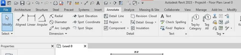
- add dimentions by the select annotation< select alined < select points <with require field.
RESULTS:
AIM 7: Identify the residential model elements such as Door, Windows, Tables, Chair, Couch, Bed, Lamps from the library and insert them to the model . Save the project for use
for Assignment 3
PROCEDURE:
- Select model eleents from load family commands.
- select door from architecture tab then we get another editing tool bar is appeared now select load family icon
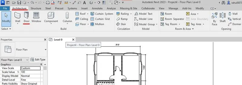
- now editing tool ar is appeared

- now select the load family icon to get pop-up window to insert element
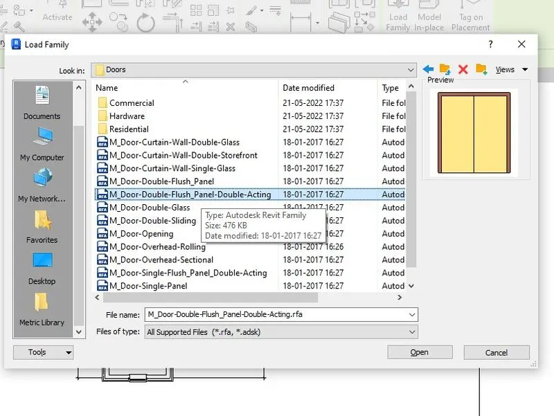
- select wich suitable for a our project
- now place where require that door element
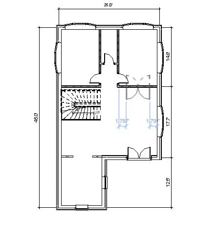
- like this we select component in tool bar < place component <select require element like chair tabile
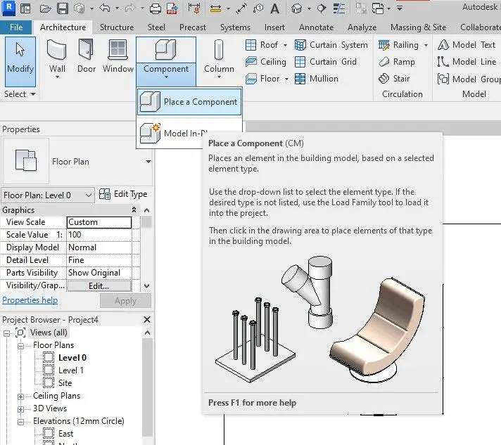
RESULTS: