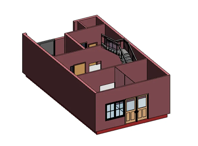
Creating Levels, Grids, Layout and model elements for a residential unit using REVIT
1) What is BIM? Summarize the features of BIM and the benefits of using BIM over 2D CAD tools.
BIM, which stands for Building Information Modelling, is a process – a methodology- for creating and managing information on a construction project throughout its lifecycle. The core element of the BIM methodology is the digital model of the building, which is a set of intelligent parametric objects that contain all the information needed during the design, execution, maintenance and even dismantling phases. More than just a simple three-dimensional representation, with BIM it is possible to create a dynamic, multidisciplinary and shared information model: the digital twin of the project that contains data on geometry, materials, structure, thermal characteristics and energy performance, installations, costs, safety, maintenance, etc.
Whereas design through CAD is developed through 2D and 3D drawing, BIM design is not limited to visual information, but also offers the designer technical information about the object being shaped and enables advanced workflow capabilities that augment the design process. The model is also at the centre of communication and collaboration between the different figures involved in the BIM process: the architectural designer, the structural engineer, the plant engineer, the client, the company, etc.
Features of BIM
The goal of using a BIM solution is to create a 3D model that users can manipulate. A 3D model enables users to understand relationships between spaces, materials, and various systems within a physical structure. BIM software can be used for every step of the process, from planning to design to construction. Every step of the process is vital to users building a structure in the real world.
Planning: BIM solutions make it possible for multiple users to simultaneously work on a design at the same time. This ensures that as many eyes as possible will see the design before it is approved
3D modelling: These tools offer users 3D modelling capabilities. Once a user has created a 3D model, it is possible to simulate and visualize various physical building elements. BIM provides insight into how real-life elements will affect a building once it is constructed.
Construction: When it is time to move forward with construction, BIM solutions let users sequence the steps and elements of the building process, including the materials and crews needed to complete the construction. Construction crews can review the 3D model within the BIM platform and perform clash detection to ensure that the design will work in the real world. Users can simulate the construction process, analyse and resolve issues, and ensure that the project is completed promptly.
The following features can typically be found in any BIM solution:
Import/export 2D designs
3D modelling
3D rendering
Sequencing steps
Document storage
Benefits of BIM
BIM offers several benefits for users. The following are just some of the advantages a business will realize from using a BIM solution:
- Accurately capture reality
- Go green
- Track project history
- Improve collaboration
- Quickly resolve conflict
- Design from any location
2) Understand the concept of Categories, Families, Elements, and Instances in Revit. Go to Insert Tab, and choose a category. Pick a family and element. Understand the instances and insert them into the Revit model
AIM:
Understand the concept of Categories, Families, Elements, and Instances in Revit. To insert categories, families, and elements into the Revit model.
Introduction:
Categories: A Category controls the organization, visibility, graphical representations, and scheduling options of Families within the Project. These are built-in Revit and can include either building components (columns, walls, ducts) or symbolic elements (tags, dimensions, regions).
Family: A Family is a grouping of 2D and/or 3D information that serves to represent a discrete building or documentation element in the Project. It defines parametric, graphical, and documentation requirements.
Type: A Type is a specific representation in a Family defined by distinct parametric, graphical, and documentation characteristics which make it unique from other Types in the Family.
Instance: An Instance is an individual representation of a Type in the Project defined by unique parametric, graphical, and documentation characteristics which make it unique from other Instances in the Project.
PROCEDURE:
Open REVIT
Open the previously created file.
Click on “load family” in the INSERT menu.
Select the desired component in the pop-up box and click open.
Now, in the ARCHITECTURE tab select the category, drop-down to view the family, and select the type of component.
Place the type in the model.
Result:
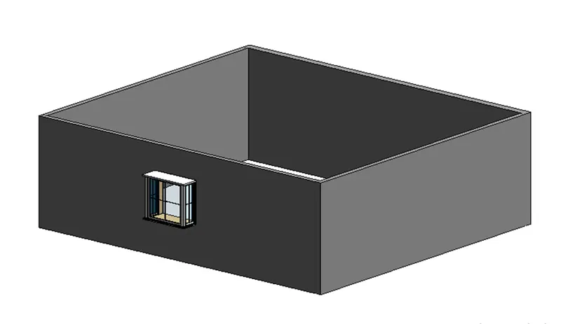
3) Setting up a Project - Open a project file with an architectural template. Save the file with an appropriate name. Set up the project units to imperial / Metric based on your convenience of modelling. Complete the project information under the Manage tab. set up the maximum backups for project files to 3
AIM:
To open a project file with an architectural template, save the file with an appropriate name, set up the project units and complete the project information under the manage tab.
PROCEDURE:
After opening Revit, click on “new” select architectural template and click ok.
Save the file with an appropriate name.
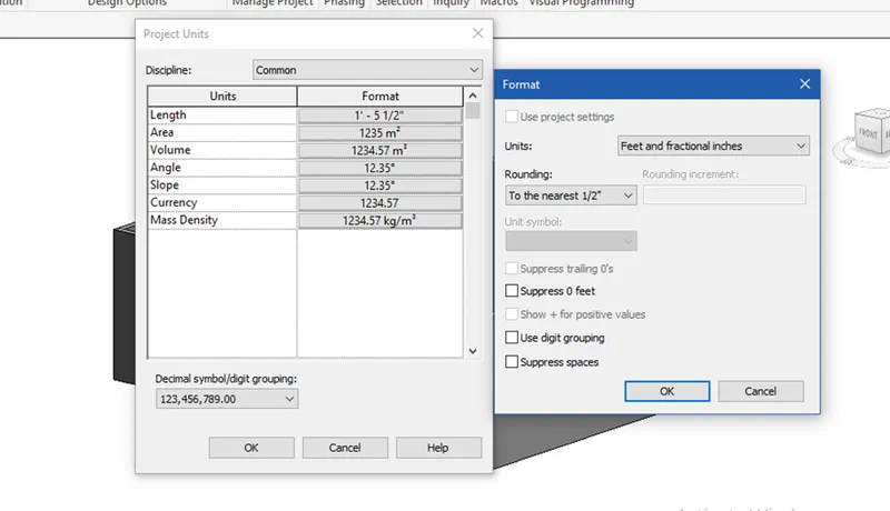
Click on “project unit” in the MANAGE> Settings tab
Click on any of the measurements, click on unit type as required, and click OK.
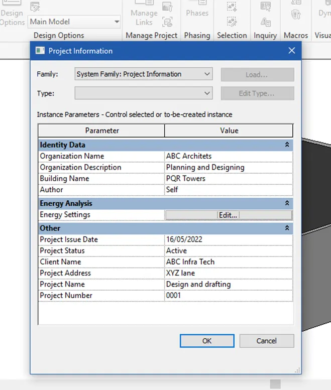
Click on “Project Information” in the MANAGE> Settings tab
Fill in the dialogue box
Go to File> Save as> Project
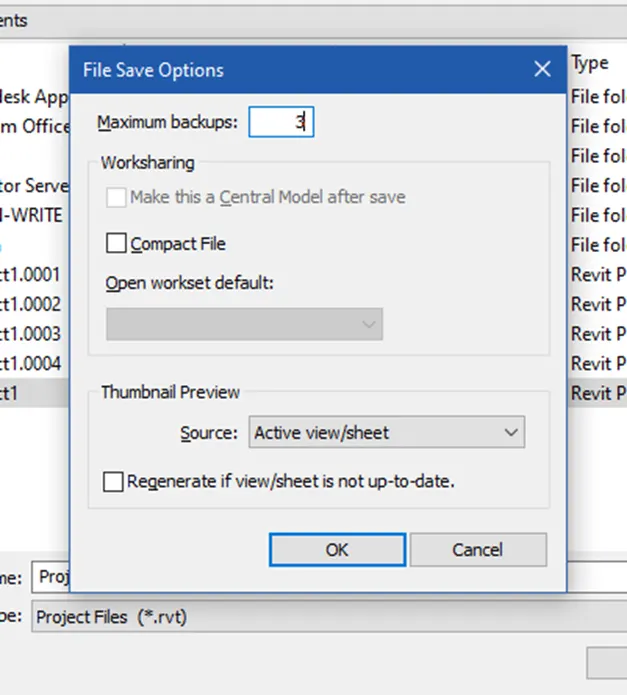
In the popup window, select “options”
Type “3” in the maximum backups
Click OK, Save.
Result:
4) Understand the concept of Levels and Grids. Follow the naming and conventions. Create the following Levels: (Convert to metric equivalents if the metric is your unit)
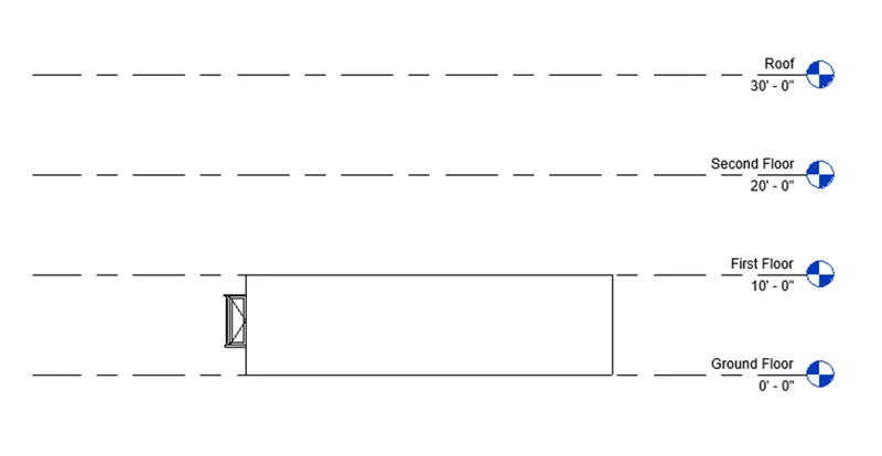
Ground Floor @ 0'
First Floor @ 10'
Second Floor @ 20'
Roof @ 30'
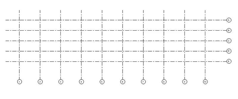
Grids Transverse Grids A, B,C,D,E @ 10' spacing
Longitudinal Grids from 1 to 10 @ 20' spacing
AIM:
To create the following levels:
Ground Floor @ 0'
First Floor @ 10'
Second Floor @ 20'
Roof @ 30'
To create grids:
Transverse Grids A, B, C, D, E @ 10' spacing
Longitudinal Grids from 1 to 10 @ 20' spacing
PROCEDURE:
Create a new project file in the architectural template, and change units to feet and inches.
In the project browser window, go to elevation and select any direction.
Go to Architecture> Datum> Level
Select the pick line option and type 10’ as offset
Now go to any plan view
Architecture> Datum> Grid
Select the line option and draw a transverse line
Then select the pick line option, taking offset as 10’ draw the rest transverse gridlines
Again, select the line option and draw a longitudinal line
Then select the pick line option, taking offset as 20’ draw the rest longitudinal gridlines
Rename the gridlines.
Result:
5) 3D modelling of the residential unit - From looking at your house / or a place you aspire. Create a conceptual layout of the residential unit. You can measure using a tape or you can access your residential plan to create a similar layout.
AIM:
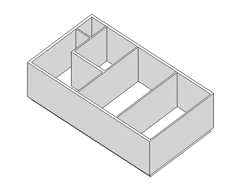
3D Modelling of a residential house, to create a conceptual layout of the residential unit.
PROCEDURE:
Open a new architectural template
Using the wall tool in the architecture menu, draw the outer boundary of the residential unit.
Complete the layout using different types of walls for partition walls and interior walls.
Create a floor using the floor tool and set boundaries for the floor.
Click on the 3D view in the top bar
Result:
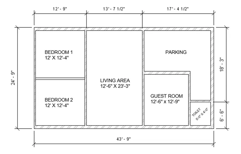
6) In the layout created draft the level of details you are planning to include - Dimensions of the room, and components you plan to add to the residential unit.
AIM:
To add details such as room dimensions and components to add to the residential unit.
PROCEDURE:
In the previously created project, go to ANNOTATE> Dimension> Linear
Measure the walls and insert the dimension lines
Go to ANNOTATE> Text
Enter the required texts at their respective places
Result:
7) Identify the residential model elements such as Door, Windows, Tables, Chairs, Couch, Bed, and Lamps from the library and insert them into the model.
AIM:
To add residential model elements such as doors, windows, tables, chairs, couches, beds, and lamps from the library and insert them into the model.
PROCEDURE:
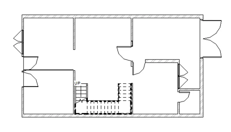
In the “architecture” tab click on doors and windows and select the place wherever they must be added.
Go to INSERT> Load family>
Add the required components
Result:
Plan view
3D View