Creating Levels, Grids, Layout and model elements for a residential unit using REVIT
AIM: Creating Levels, Grids, Layout, and model elements for a residential unit using REVIT
INTRODUCTION: The main aim here of this challenge is to introduce the basic functions of the REVIT and also teach how to use GRIDS, LAYOUTS, LEVELS & thus create a model in the software. This challenge contains seven different challenges which expose students to different types of functions of the REVIT and help the students to follow a basic procedure when they start creating a project. All the questions are answered briefly. Please have a look below in the question sections. Snips for each question (wherever required) are given to show the step-by-step procedure of the challenge question.
QUESTIONS:
1) What is BIM? Summarize the features of BIM and the benefits of using BIM over 2D CAD tools.
ANSWER:
BIM stands for Building Information Modeling. Many see Building Information Modelling as the natural evolution of CAD. What BIM is not is a type of CAD package. Instead, it’s a design methodology that you can use independently of CAD. However, most use CAD as part of the BIM method. Two things lie at the heart of BIM: collaboration and sustainability. BIM allows you to bring all your designs, including CAD models, into a single database. Using the cloud, BIM provides access to this database to all project members. You’ll all work on the same models, which allows for quick changes as needed. When used correctly, BIM helps the entire team visualize the project. This is one of the main benefits of BIM in construction. The team can spot project issues before construction even starts. That’s because of the sustainability aspect of BIM. The methodology allows you to design every aspect of a building. In addition to the building itself, BIM models feature electrical wiring and other important aspects of design. This creates a more realistic digital representation of the final product.
The benefits of BIM over 2D CAD tools are given as follows:
- Time-saving
- Integration with different software
- Lesser errors
- Simplicity
- No complex issues
- Can be collaborated.
- Cloud working
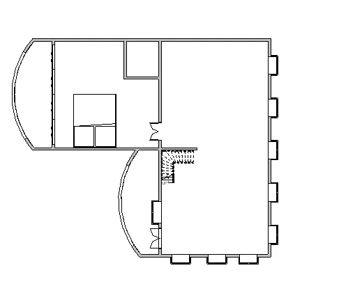
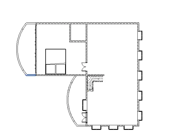
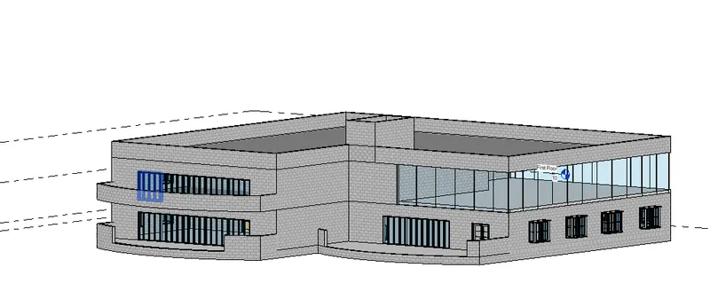
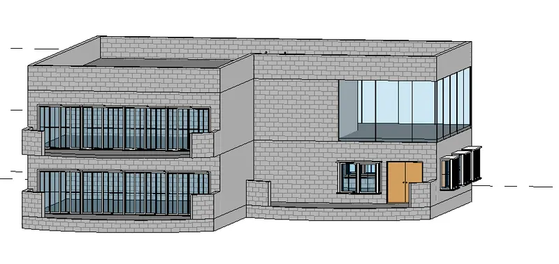
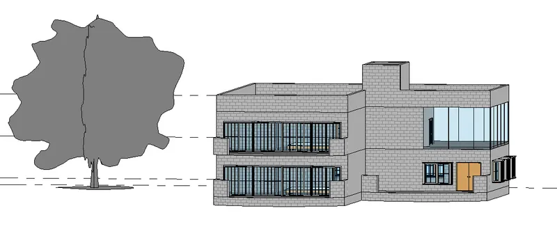
2) Understand the concept of Categories, Families, Elements, and Instances in Revit. Go to Insert Tab, and choose a category. Pick a family and element. Understand the instances and insert them into the Revit model
PROCEDURE:
- Open the REVIT software and open the challenge 1 project sheet.
- Now go to the insert tab.
- Choose any category from the list.
- Pick the family whichever you like and select an option under the family!
- Insert those picked-up elements in the model!
- To insert it into the model, just take the cursor to the desired location where you want to add the element to it and just left-click on the mouse to insert it!
- For more clarity, please have a look at the below snips.
RESULTS: The concept of categories and families and elements was introduced! The steps to insert different families into the model were taught! Please have a look at the below snips for more clarity.
SNIPS:
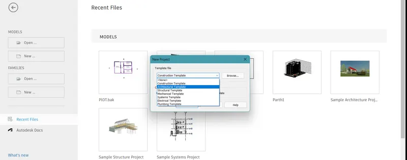
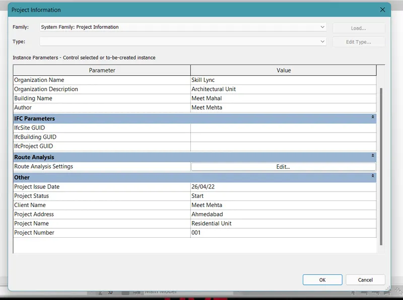
3) Setting up a Project – Open a project file with an architectural template. Save the file with an appropriate name. Set up the project units to Imperial / Metric based on your convenience of modeling. Complete the project information under the Manage tab. Set up the maximum backups for project files to 3
PROCEDURE:
- Open the REVIT software.
- In the window of the new section, click on the architectural template under the project type section.
- Now go to the manage tab or simply type UN on your keyboard, and a dialog box appears.
- Change the units of the quantities wherever required.
- Now in the manage tab click on the icon for the project information command.
- A dialog box opens up,
- Add the necessary details to it.
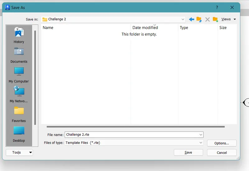
- After adding the details save the file at the desired location!
- Once saved, also save the same file copies at different locations just to have more than 1 backup.
- For more clarity please have a look at the below snips.
RESULTS: A new project in the Architectural template having Imperial project units were created and saved with multiple backups. Please have a look at the below snips for more clarity
SNIPS:

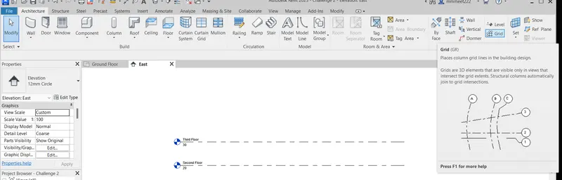
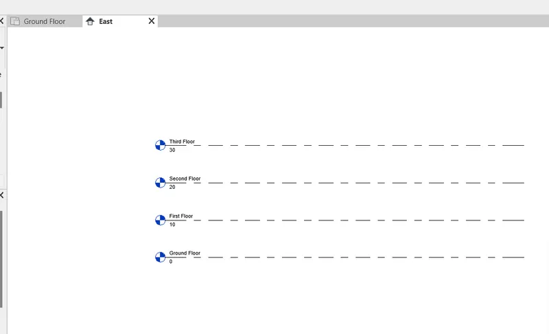
4) Understand the concept of Levels and Grids. Follow the naming and conventions. Create the following Levels: ( Convert to metric equivalents if the metric is your unit)
Ground Floor @ 0’
First Floor @ 10’
Second Floor @ 20’
Roof @ 30’
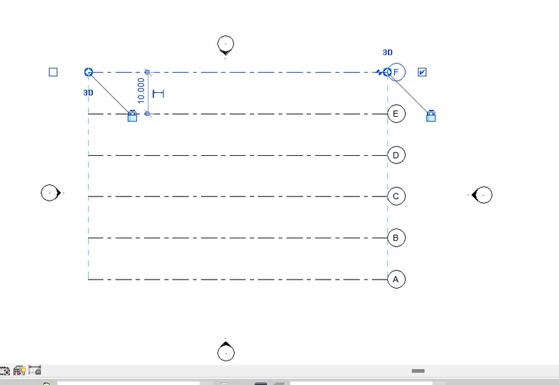
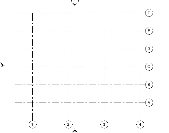
Grids Transverse Grids A, B, C, D, E @ 10’ spacing
Longitudinal Grids from 1 to 10 @ 20’ spacing
PROCEDURE:
- Open the Challenge 2 file which was created in the above question.
- Create different levels as asked in the question.
- To create levels, go to any elevation, and right-click on any level.
- In the drop-down list, click create a duplicate and rename it as you like.
- Thus the levels are created.
- Now for grids, go to the architecture menu.
- Click on the grids and start adding grids at a given distance in the question.
- For more clarity please have a look at the below snips.
RESULTS: Three different levels apart from the ground were created. Grids were created. Please have a look at the snips for more clarity.
SNIPS:
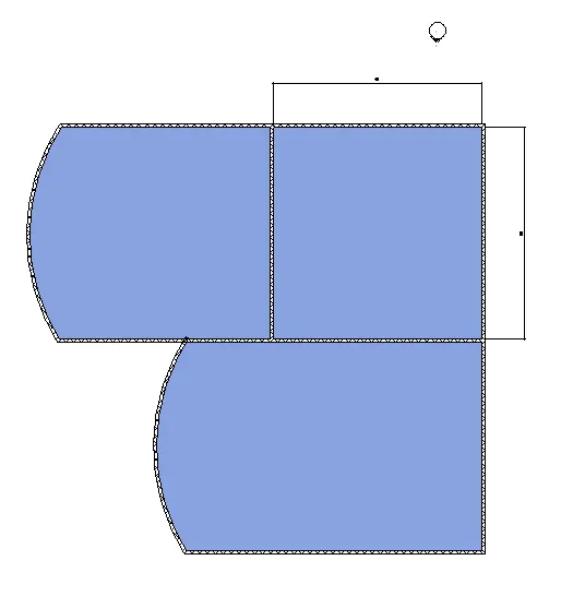
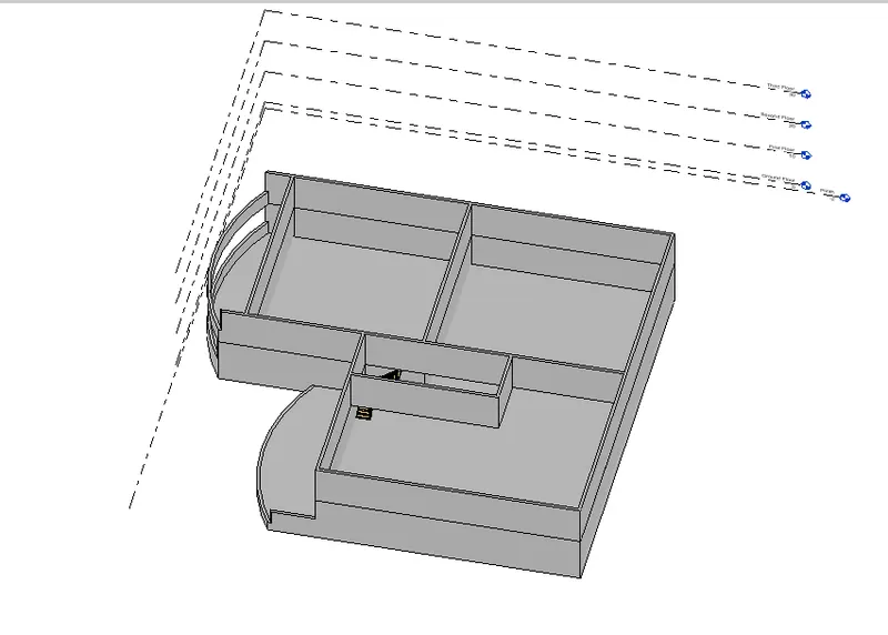
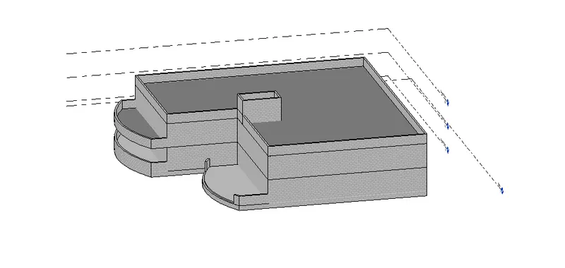
5) 3D modeling of the residential unit – From looking at your house / or a place you aspire. Create a conceptual layout of the residential unit. You can measure using a tape or
you can access your residential plan to create a similar layout.
PROCEDURE:
- Open the Challenge 2 file created in the above question.
- Have a deep thought process of how would you wish to have your residential unit be.
- Once clear with it, give levels to it and then start with the outer perimeter walls.
- Now create the partition walls with a wall thinner than the outer wall.
- Thus, create the whole layout of the residential unit.
- After creating the walls, start adding floors to them!
- Create floors for both the levels and then create a roof at the top-most level.
- Now give grid lines to the walls.
- Have a look at the below snips for more clarity!
RESULTS: A 3D model of a residential unit with grid lines was created. Please have a look at the below snips for more clarity!
SNIPS:
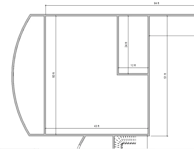
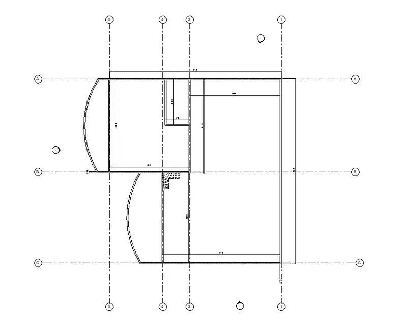
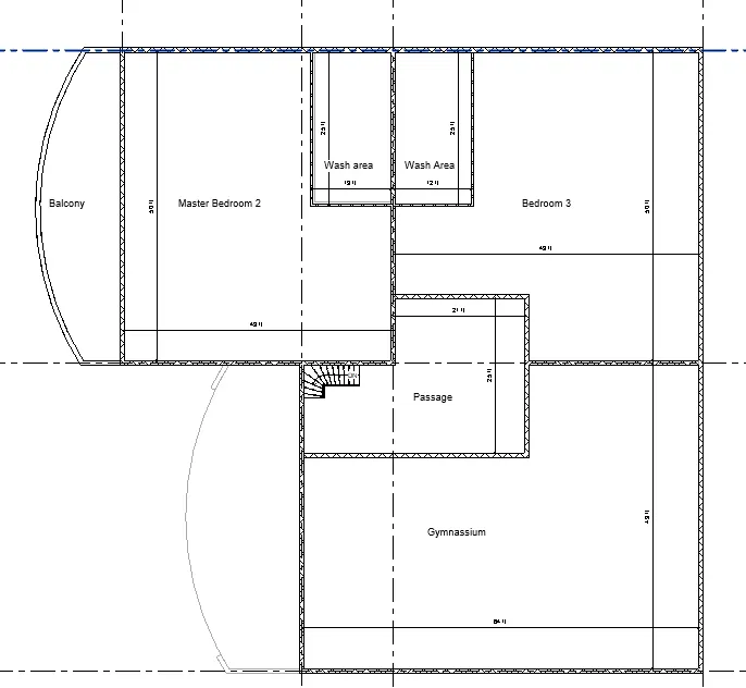
6) In the layout created draft the level of details you are planning to include – Dimensions of the room, components you plan to add to the residential unit.
PROCEDURE:
- Now in the 3D model created in the above question, start giving details to it.
- Start giving dimensions, grid lines, and annotations.
- Add as much detailing as possible.
- Please have a look at the below snips for more clarity.
RESULTS: Details were added to the 3D model of the residential unit! Please have a look at the below snips for more clarity!
SNIPS:
7) Identify the residential model elements such as Door, Windows, Tables, Chairs, Couch, Bed, and Lamps from the library and insert them into the model. Save the project for use
for Assignment 3
PROCEDURE:
- Now after giving the details to the project, start adding the components to it.
- Go to the insert bar and add libraries of whichever components you wish to use.
- Add doors, windows, furniture, bed, lights, tables, etc, etc.
- Add as many detailed components as you can add to make it look more and more realistic!
- Please have a look at the below snips for more clarity!
RESULTS: Door, Windows, Tables, Chairs, Couch, Bed, and Lamps from the library were inserted into the model. Please have a look at the below snips for more clarity!
SNIPS: