Creating Levels, Grids, Layout and model elements for a residential unit using REVIT
Aim: To create the levels, grids, layout and model elements for resdential using the revit.
Introduction:
Revir is a 3D parametric modelling software package for building information modelling (BIM). parametric modelling means you can create each of the following from within the tool, providing a single database for all the elements involved in the design. Revit is an tool for architects, drafters, mechanical engineers, MEP engineers, structral engineers, designers, contractors, aand more. we can model internal components in 3D, annotate designs for planning purpose and much more. one of the most important features of the revit is its ability to keep track of all relationship between different parts of model.
Levels and grids are really the skeleton of building projects. Typically levels in the revit are used to indicate the location of the floors, foundation, and the roof of the building in section and elevation views. these are the finite planes that help to define the project context. these act as reference line for the floors , roofs, ceiling etc.
1. What is BIM. summarize the features of the BIM and benefits.
BIM
- BIM is a visual representation of the physical and functional characteristics of a facility form inception onwards, as such it serves as a shared informationb reposity for the collabration throught life cycle.
- BIM is an acronym for building information modeling or building information management. it is a highly collabrative process that allows the architects, engineers, real estate developers, contractors, manufactures, and other construction profesionals to paln, design, and construct a structure or building within one 3D model.
Features of the BIM
- Easy Access to information : BIM is a physical representation of the physical and fuctional charecteristics of the buildingprocess that provides every minute detail of the project. Every stake holder makes their discipline specific input to make it a comprehensive shared information resource about the structure. One can easily access the right information at the right time that provides a reliable basis for decision making during a structure entire lifecycle.
- Making the process more extensive: CAD software enables users to work accurately in 3 dimensions length, breadth and depth. However BIM modelling services provides, are allowed to work in five dimensions, time and cost being the additional dimension. They are thus able to produce accurate cost and material estimates and precise time schedules of the project even as the design is being developed.
- Move comprehensive overviewv of the project: BIM models not only present 3D geometric view of the structure, they provides a more comprehensive overview of the entire building process. It covers every components of the process from geometrical aspect of the design to spatial relationships, from light analysis to provision of verious services, from topographical information to quantities or propertioes of the building components.
- Lifelike views: BIM design tools allow you to obtain various views from a building model and produce a high quality, accurate drawings. These views are based on a single definition of each object thus gives more realistic and accurate idea of the final structure.
Benefits of the BIM:
- Cost and resource saving: One significant benefit of the BIM is that it provides reliable construction cost estimates long before the construction phase begins. It estimates cost related to materials, material shipping, Shipping prefabricated or modular pieces, Labour including payrolls based construction timelines. Not only does this give architects a better idea of how much the projects will cost but it also helps them discover ways to reduce the costs.
- Greater efficiency and shorter project lifecycles: With using the BIM the architects can design the building faster and start the construction earlier. Improved workflow and other efficiencies also speed up the project.
- Improved communication: BIM improves communication among architects, clients, contractors and other relevant properties involved in the project. Thst because BIM relies on a single source of truth system this means that all of the relevant information including models, estimates, and design notes are shared and stored from one place everyone involved in the project can see the information and even offer the suggestions of their own. It's a true collabration that eliminates information silos and helps architects find the best solutions based on the data analytics.
- More oppurtunities for prefabrication and modular construction: BIM software is ideal for makong the detailed production models that can later be prefabricated off site. designers are also have more opprtunities to design the modular pieces of the architecure that fit prafectly together and include complex tolerance calculations.
- Higher quality results: While the benefits of the BIM are most evident in the design and construction process clients may also notice an improvement in the build quality. using the BIM makes the calculations and models more detailed and accurate, and this results in a higher quality structure.
- Better coordination and Clash detection.
- Mitigate the risk and reduce the cost.
- Improved scheduling/sequencing.
2. Understand the concept of categories, families, elements, instances in the revit. Go to insert tab choose the category pick a family and element. understand the instances and insert it to revit model.
Concept of category, family, type and instances in the revit
- Category: it controls the oreganisation, visibility, graphical representation and scheduling options of the families within the project. elements that have similar properties and functionality are organized into a categories.
- Family: It is the group of 2D and 3D information that represents the building or documentation elements in the projects define parametrical and documentation requirement. Sub groups of category are that have more specific requirements are called families. for example door categories are can be broken into double flush and single flush door families.
- Type: Specific representation of the family defined by distinct parameter such as graphical documentation, characteristics which make unique from other families. the type determines most properties of the elements in the family categories and usaually based on the shared dimensions.
- Instance: Individual representation of a type in the project defined and documentational characteristics. each elements placed in the revit is called instance.
- Elements: Each component or model item is called an element. this can be include components like walls, doors, and windows, as well as datum elements like gridlines, notes, and dimensions which are stored in the hierarchical system.
Procedure:
- Open the revit from the model select the new and select the architectural template.
- from the file menu select the save option and select the project and give the require naame and save
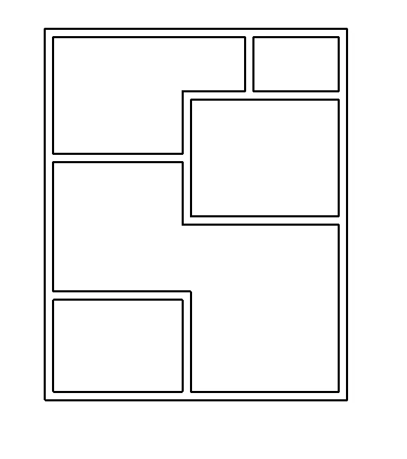
- From the architectural tab select the architectural wall and the wall created of required diimensions.
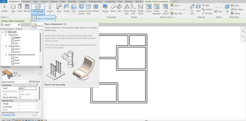
- From the architectural tab select the component and from that select the place component.
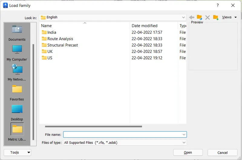
- from project properties select the door and moddify tab select the load family.
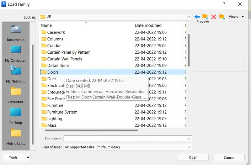
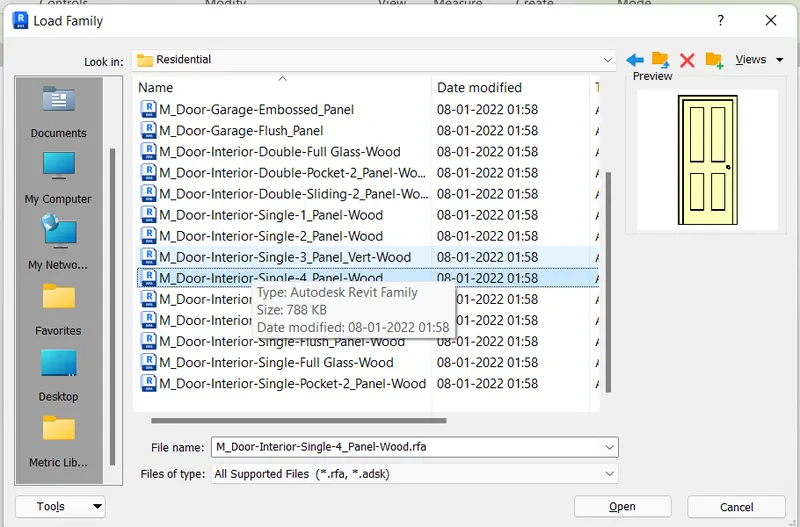
- for creating of the door after click on the load family click on US>doors>residential
- Select the required door and size and it is placed at the requireed position.
- For the placing of the window Window>load family>US>windows
- Select the required window and placed it at required position
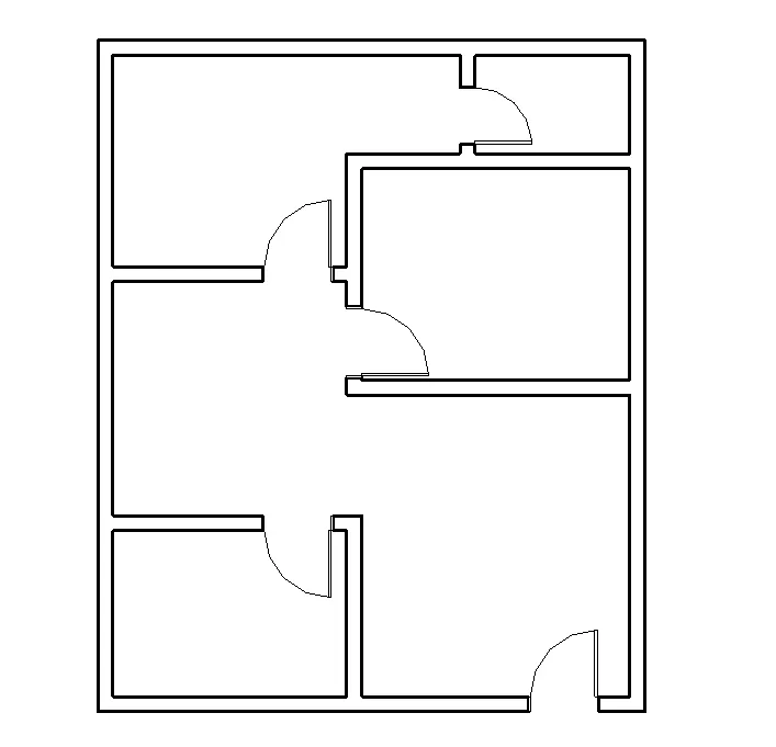
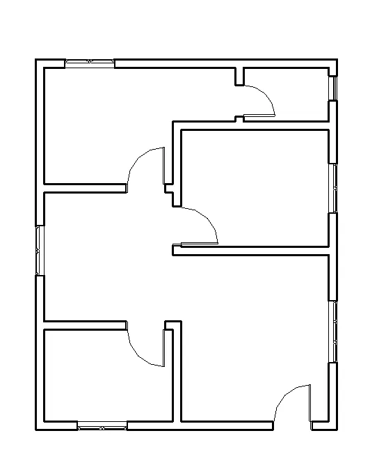
Result:
3.
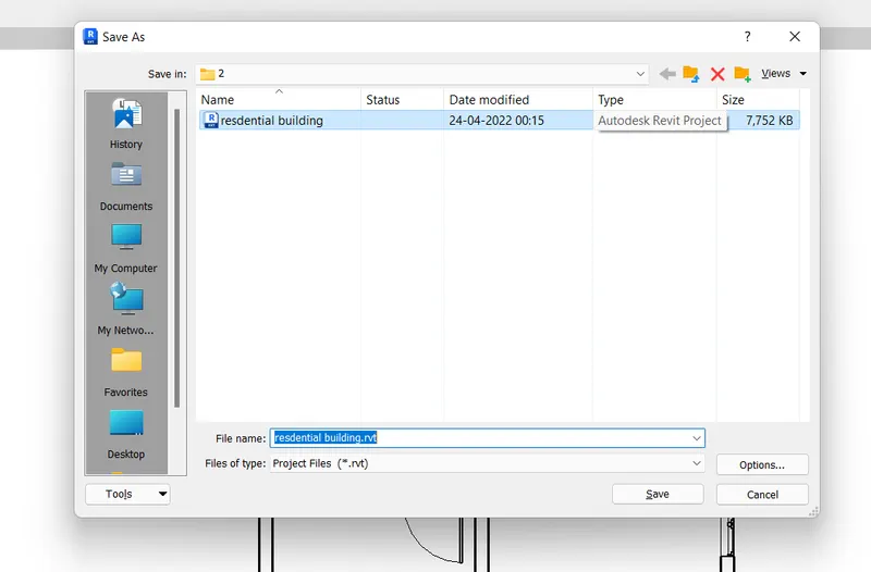
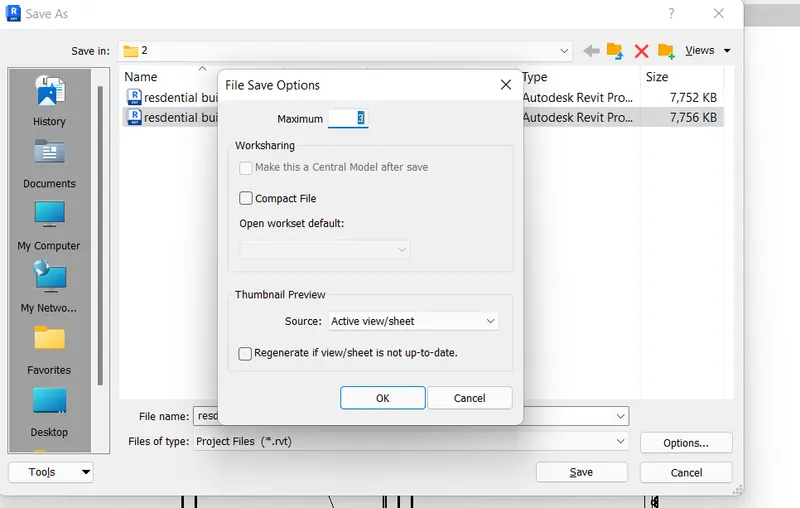
Setting up the project - open a project file with archtectural template. save the file with appropriate name. setup the project name with metric/imperial based on your convnience of the modelling. complete the project information under manage tab. set up the maximum backups for the project file 3.
Procedure
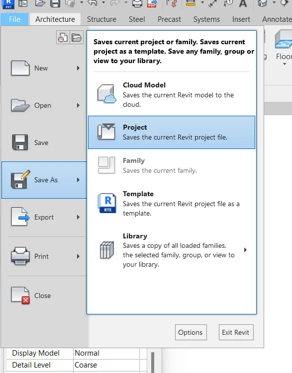
- Click on the file menu and select the save as option and click on the project.
- Select the folder to save the revit drawing and give the name of the file and saved it.
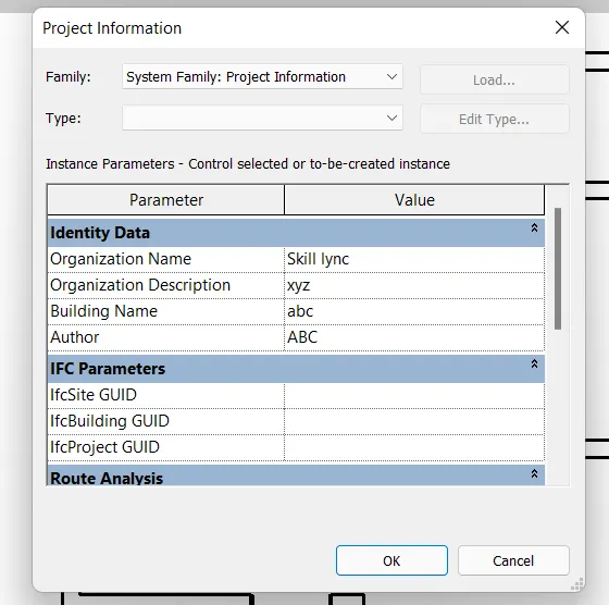
- From manage tab click on the project information after clicking the project information dialogue box will appear.
- fill the all details such as organization name, description, author name, adress etc and click ok option.
- from the file menu select the save as option and click on the project.
- click on the option gibve the maximum backup as a 3
- type UN and set the units to feet
4. Understand the concept of levels and grids. follow the naming and conversation. create the following levels
Ground floor @ 0'
first floor @ 10'
Second floor @ 20'
Roof @ 30'
Grids transverse grids A, B, C, D, E @ 10' spacing
Longitudinal grids from the 1 to 10 @ 20' spacing.
Levels and grids
Creation of the levels
- Open the revit.
- from the model select the new in that select the architectural template.
- From the project browser click on the elevation and select the east.
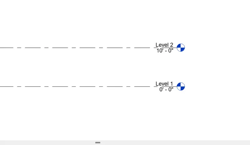
- initially two levels are created by the revit with the name of level 1 and level 2
- from the architectural tab select the level from the datum
- From the modify the option select the pick line and give the offset 10'
- and select the pick line level 2 the next level that is level 3 is created like tghis another level is created.
- change the levels name to ground floor, first floor, second floor and roof
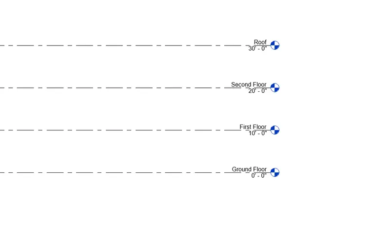
Creation of the longitudinal and transverse grids
- Select the floor plan from the project browser.
- From the architectural tab select the grid
- From the draw option select the line
- Draw the first grid and it comes with the name 1 change the name to A.
- Select the pick line and give the offset 10' and select the first grid A and next grid will appear.
- Like this other grids are created upto grid E
- For the creation of tye transverse grid select line
- Create the one longitudinal grid and name it as 1
- Select the pick line and give the offset 20' and select the longitudinal grid
- placed the next grid at left side
- Like this other grids upto grid 10 is created.
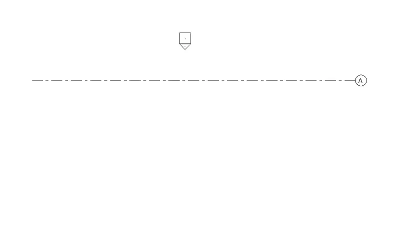
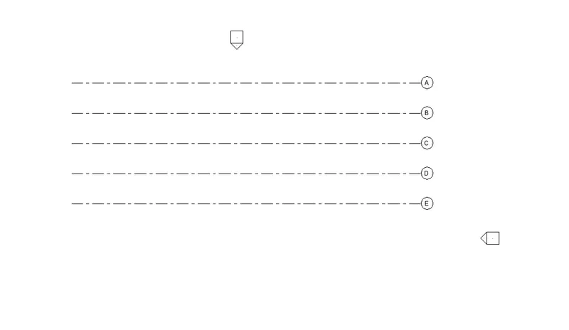
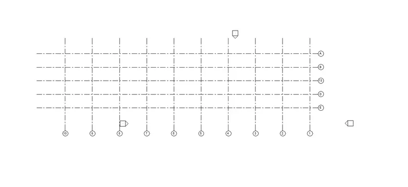
Result:
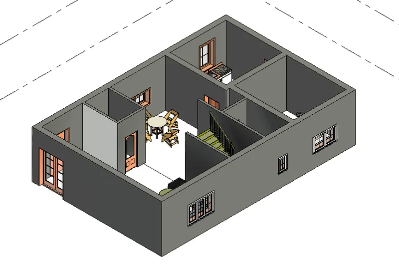
5. 3D modelling of of residential unit - from looking at your house / or a place you aspire. create a conceptual layout of the residential unit. you can measure using a tape or you can access your residential plan to create the similar layout.
3D modelling of the residential unit
- Open the revit.
- from the model select the new in that select the architectural template.
- from the menu select the save option and save the project as a residential building.
- From the manage tab select the project information and enter deatails of the project.
- From the architectral tab select the architectural wall.
- From the project properties select the generic 12" wall
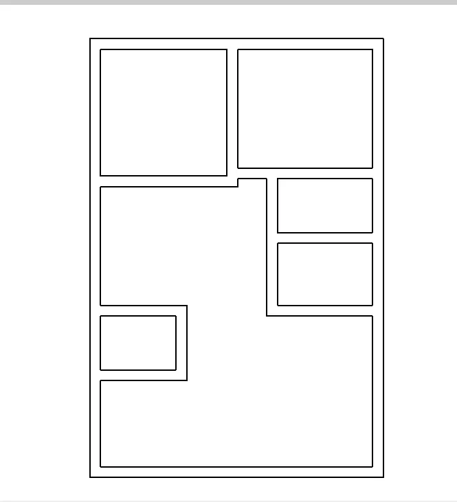
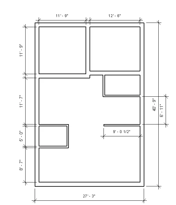
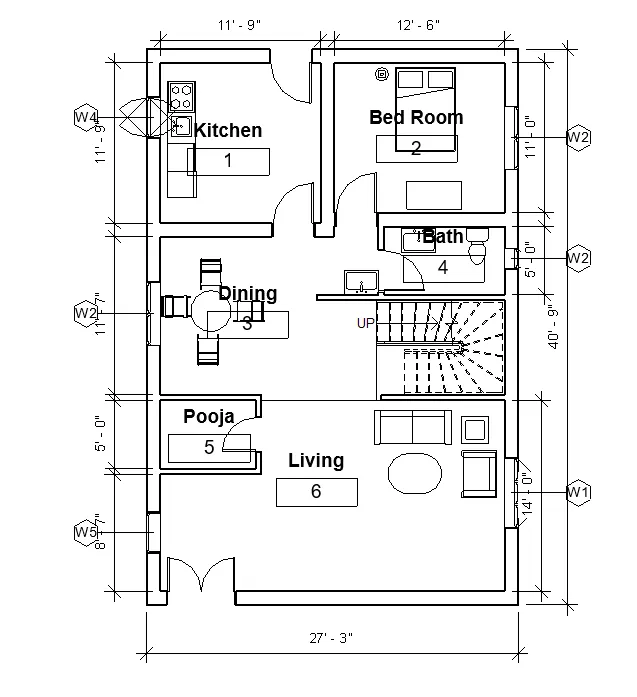
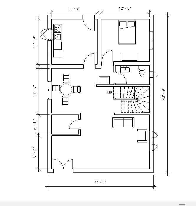
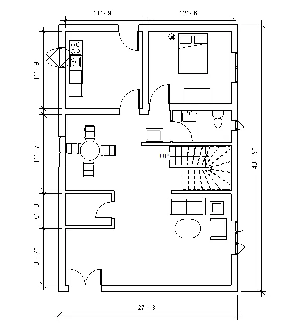
- Select the line and draw the 11'9" right side and 11'9" downward and move the left side upto straight line appears from the top line and join the first point.
- from the top right corner start the next wall with a distance of 12'6" and 11'0" downward join longitdinal wall.
- Draw 5' downward and 9'6" left side and join the above wall.
- draw a wall of 6'11" downward and 9'6" left side.
- select the internal wall change the wall to generic 5" wall.
- draw downward 14'0" and 27'3" left side and join transvere wall.
Result:
6. In the layout created draft the level of details you are planning to include - dimensions of room, components you plan to add in the residential unit.
Procedure for Dimensions to layout
- The layout is created in the question 5
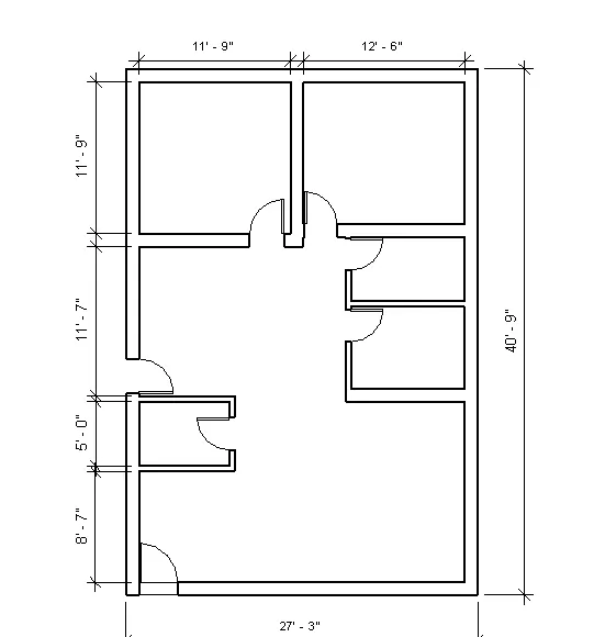
- Select the annotate tab select the linear dimensions.
- Select the two points that dimensions required and the dimensions are given.
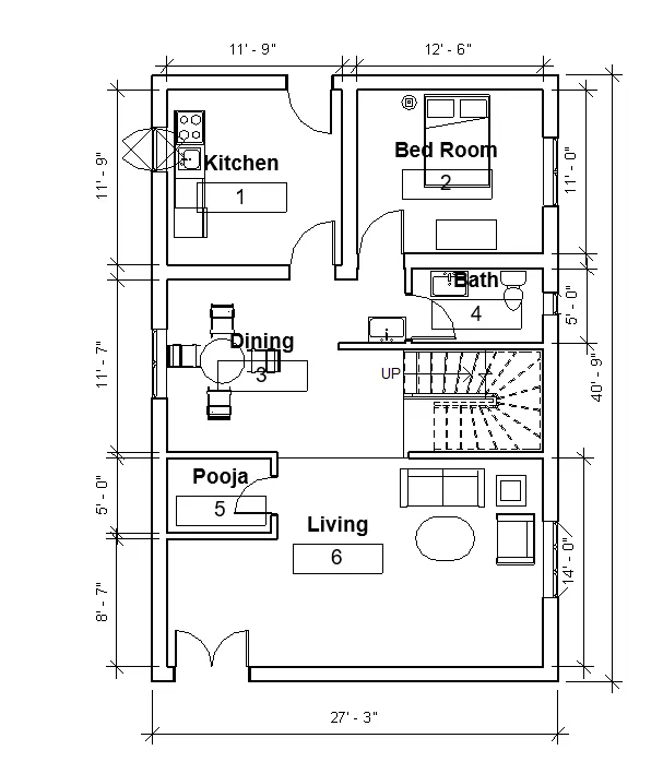
- from the srchitectuurak tab select the room tag and it is created for the every room
- Change the room name.
- Doors and windows selected in placed it at required position.
Result:
7. Identify the residential model elements such as door, windows, tables, chair, couch, bed, lamps from the library and insert them to the model. save the project for use for assignment 3.
Identify the residential units such as doors, tables, couch, bed, lamps, from the library and insert them to the model.
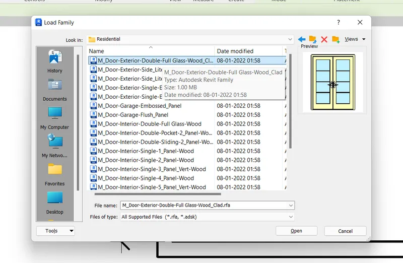
- Select the architectural tab from that select the door.
- select the load family US>Doors>residential
- The below dilogue box will appear.
- Select the required door for the project and select the size of the door
- place the selected the door at the required position.
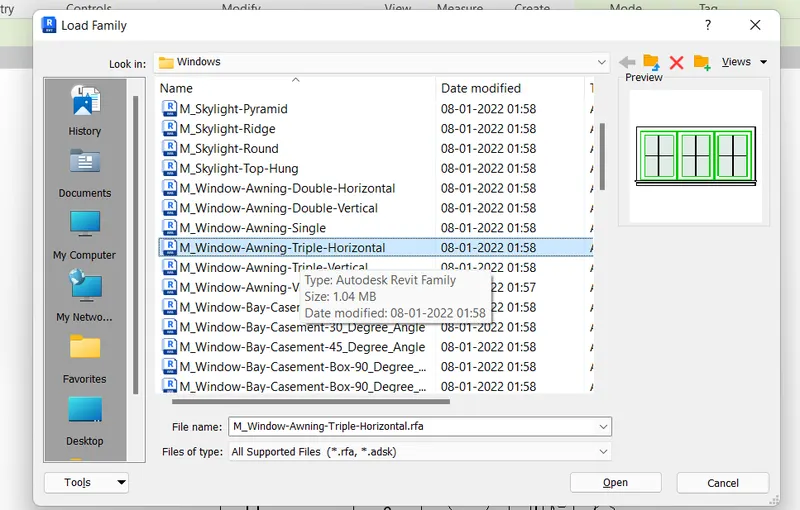
- from the select the window and select the load family.
- select the window elements and select the required window and placed it at required position.
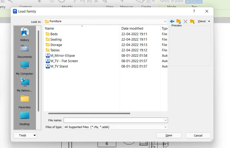
- Similarly table, lamp are palced at the required position.
Result: