Creating Levels, Grids, Layout and model elements for a residential unit using REVIT
CHALLENGE 2
Q1: What is BIM? Summarize the features of BIM and the benefits of using BIM over 2D CAD tools
Answer: BIM is a visual representation of the physical and functional characteristics of a facility from inception onwards. It serves as a shared information repository for collaboration throughout a facility's life cycle. BIM allows the members of the project team to generate a virtual model of the structure and all of its systems in 3D and enables them to share that information.
Following are the features of BIM
- Easy access to information: BIM is a physical representation of both physical and functional aspects of the building process that provides very minute details of the project
- Makes the process more expressive: BIM allows us to work in 5 dimensions ie, length, breadth, depth, time and cost. Thus it makes us able to produce accurate costs and material estimates, precise time schedule of the process even as the design is being developed.
- A comprehensive view of the project: BIM model represents a more comprehensive overview of the entire building process. It covers every component of this process from geometrical aspects of the design to the spatial relationship from light analysis to provision of various services from topographical information to quantities on properties and so on.
Following are the benefits of BIM over 2D CAD tools.
- BIM provides a complete representation of the building design.
- BIM allows providing instant updates of the building components
- BIM allows fabricating the components of a building ahead of time since such details are part of the design
- BIM enables us to figure out how much of each resource is needed during the design stage itself.
Q2: Understand the concept of Categories, Families, Elements, Instances in Revit. Go to Insert Tab, choose a category. Pick a family and element. Understand the instances and insert them into the Revit model
Answer:
Category: It is one of the Revit element hierarchies. It controls the organization visibility, graphical representations and scheduling options of families within the project.
Family: It is a group of 2D or 3D information that represents a discrete building or a documentation element in the project. It defines parametrical graphical and documentation requirements.
Type: It is a specific representation in a family defined by distinct parametric, graphical and documentation characteristics which makes it unique from other types in the family.
Instance: It is an individual representation of a type in the project defines by unique parametric, graphical and documentation characteristics which makes it unique from other instances in the project.
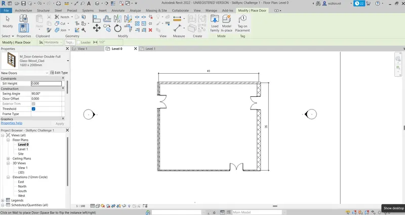
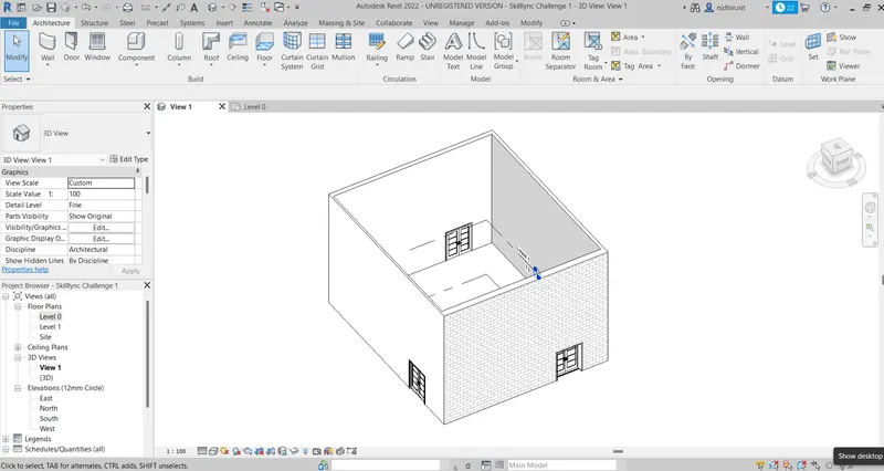
Procedure to insert instance in a Revit model
- Open the existing Revit model
- To insert a door, go to the Architecture tab and select door
- Click on load family
- Click on the US folder
- Click on the Door category folder
- Click on the residential folder
- Select M_Door-Exterior-Double-Full Glass-Wood_Clad
- Select the size of the door
- Place the door in the model as per requirement
Q3: Setting up a Project – Open a project file with an architectural template. Save the file with an appropriate name. Set up the project units to Imperial / Metric based on your convenience of modelling. Complete the project information under the Manage tab. Set up the maximum backups for project files to 3
Answer:
Aim: To complete the project information of a Revit project, set up maximum backups for the project as 3 and illustrate the procedure involved.
Procedure :
- Open the Revit software
- Click New and select the Architecture
- Click on the File option, select Save as and save the project with a file name Skilllync Challenge 2
- Go to the Manage tab and click on project information
- Enter the Organization Name as Skilllync
- Enter the organisation description as Skilllync Building
- Enter the Building name as ABC Building
- Enter the Author name XYZ
- Ente the project issue date 17/02/22
- Enter the project status as Active
- Enter the client name as ABC
- Enter the project address as Dubai
- Enter the project name as ABC Building Project
- enter the project number as 001
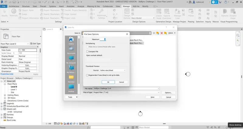
- Go to the File option and click on save as
- Click on the project and click on options
- Enter 3 as the maximum number of back up click ok and save
Q4: Understand the concept of Levels and Grids. Follow the naming and conventions. Create the following Levels: ( Convert to metric equivalents if the metric is your units)
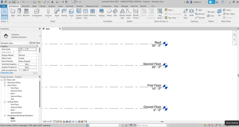
Ground Floor @ 0’
First Floor @ 10’
Second Floor @ 20’
Roof @ 30’Grids Transverse Grids A, B, C, D, E @ 10’ spacing
Longitudinal Grids from 1 to 10 @ 20’ spacing
Answer:
Aim: To create levels, longitudinal and transverse grids in Revit and illustrate the procedure involved.
Procedure to create levels:
- Open Revit software
- Open a new project by selecting the architecture template
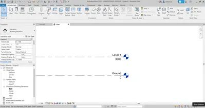
- Go to the elevation and select East
- Rename level 1 as ground floor by double-clicking
- Rename level 2 as the first floor by double-clicking
- Go to the Architecture tab and select Level
- Set offset distance as 10'
- Select the pick lines option and click on the first floor to create Level 3
- Continue the same procedure to create level 4
- Rename level 2 as the first floor by double-clicking
- Rename level 2 as the first floor by double-clicking
Procedure to create Grids:
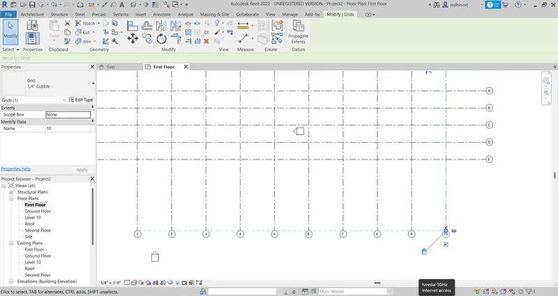
- In the same project go to the first-floor view
- Go to the Architecture tab and select the grid option
- Select the line option and create the first transverse grid
- Set the offset distance as 10' and select the pick lines option
- Using the pick lines option create second, third, fourth and fifth gridds
- Rename grids 1,2,3,4, and 5 as A, B, C, D, E and F by double-clicking
- Again go to the Architecture tab and select the grid option
- Select the line option and create the first longitudinal grid
- Set the offset distance as 20' and select the pick lines option
- Using the pick lines option crate another 9 grids
- Rename the grids from 1 to 10 by double-clicking
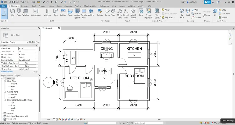
Q5: 3D modelling of the residential unit – From looking at your house / or a place you aspire. Create a conceptual layout of the residential unit. You can measure using a tape or
you can access your residential plan to create a similar layout.
Answer:
Aim: To create a conceptual layout of a residential unit and illustrate the procedure involved.
Procedure:
- Open the Revit software
- Go to the east elevation and set the levels
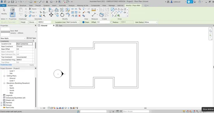
- Go to the Architecture tab and select wall
- Select generic wall-200mm from the property browser
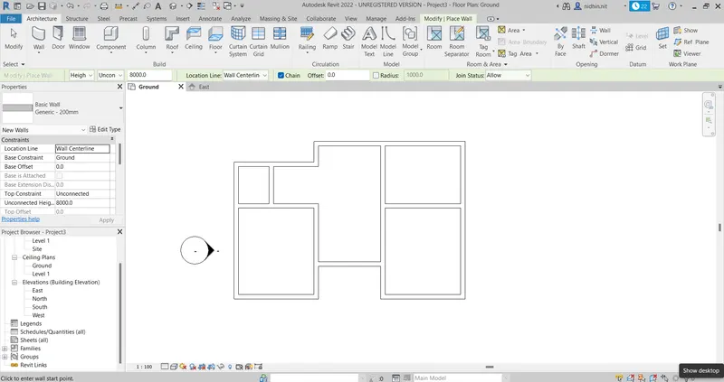
- Using the direct distance method create the layout
- Go to the architecture tab and select the room option
- Select the rooms as per the design
- Double click on the tag and give suitable names to the room
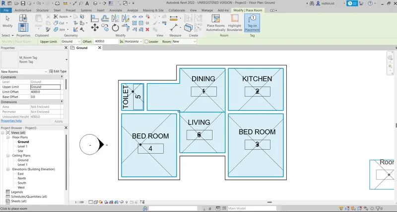
Q6: In the layout created to draft the level of details you are planning to include – Dimensions of room, components you plan to add in the residential unit.
Aim: To include dimensions of the rooms for the conceptual residential layout created and illustrate the procedure involved.
Procedure:
- Go to the ground floor view
- Go to the Aonnotaet tab
- Select the linear dimension option
- Dimension the rooms
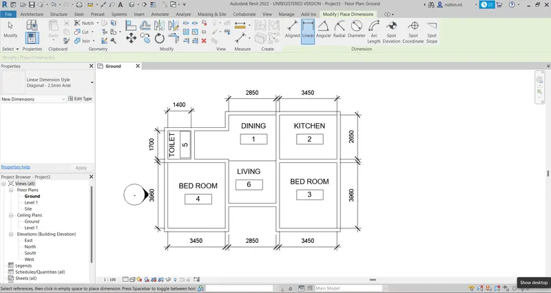
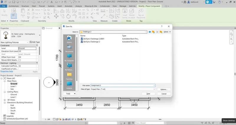
Q7: Identify the residential model elements such as Door, Windows, Tables, Chairs, Couch, Bed, Lamps from the library and insert them into the model. Save the project for use
for Assignment 3
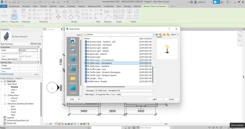
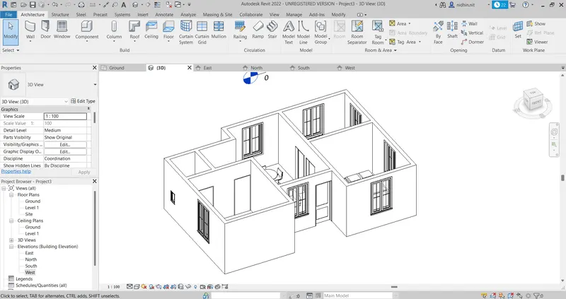
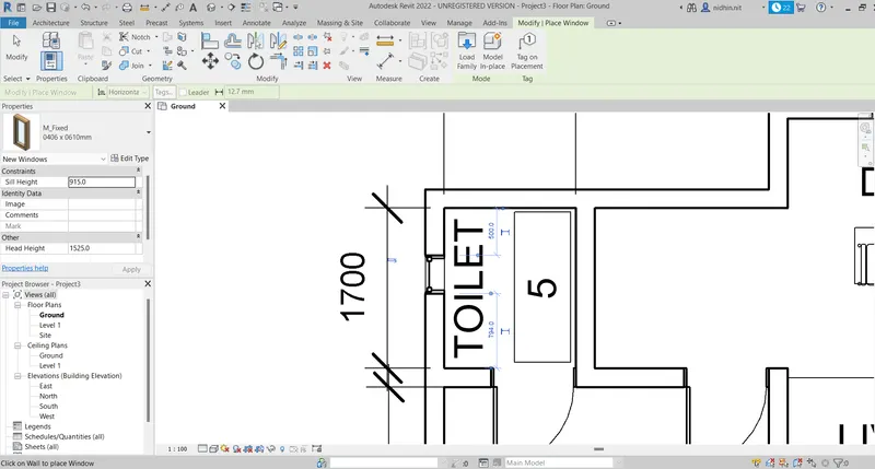
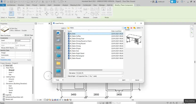
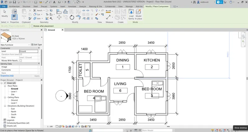
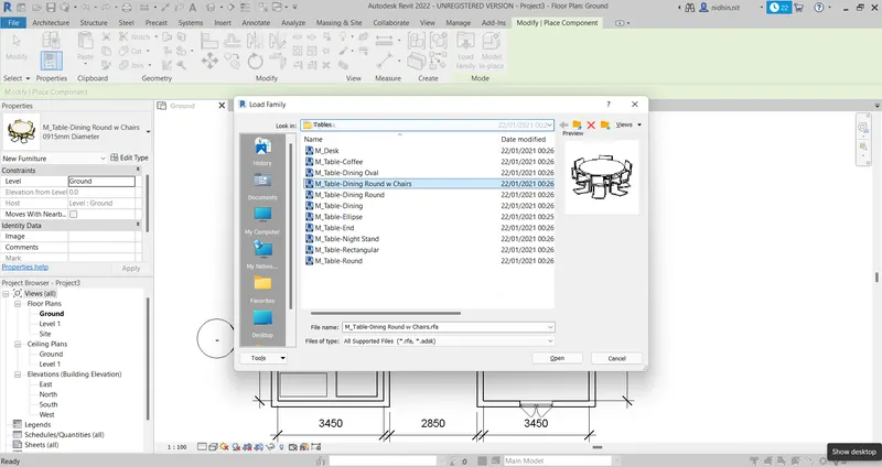
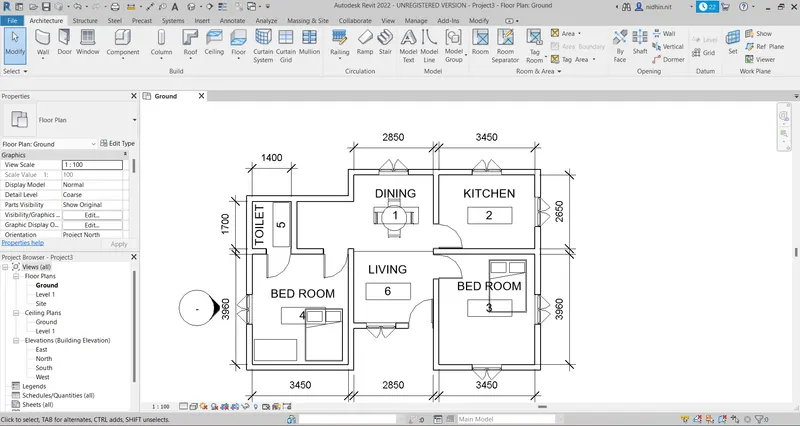
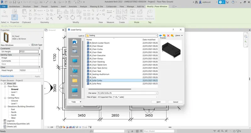
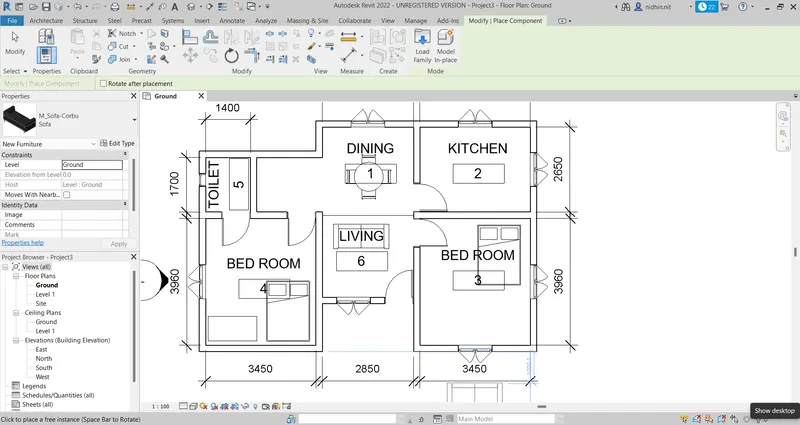
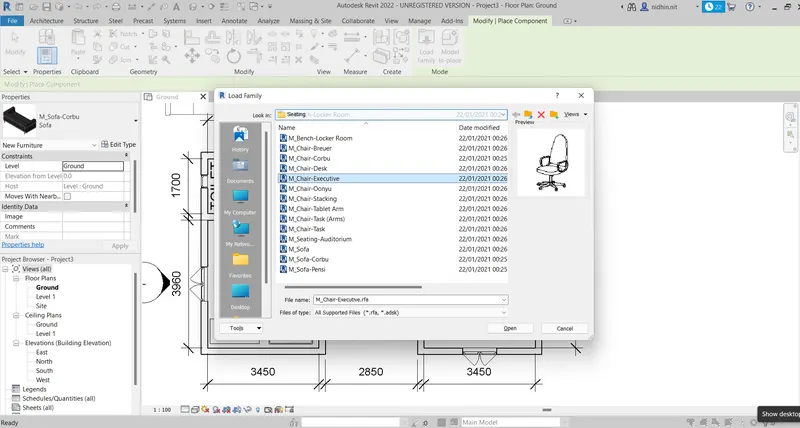
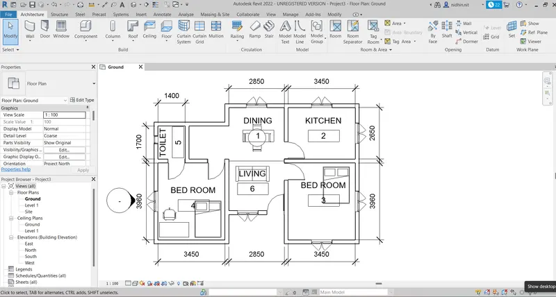
Aim: Insert residential model elements such as doors, windows, tables, chairs, couches, beds and lamps from the library to the created model and illustrate the procedure involved.
Procedure:
- Go to the architecture tab
- From the component option select the place a component option
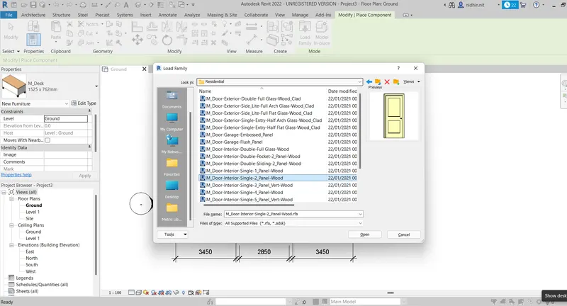
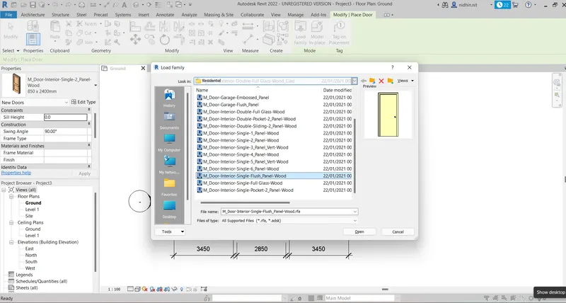
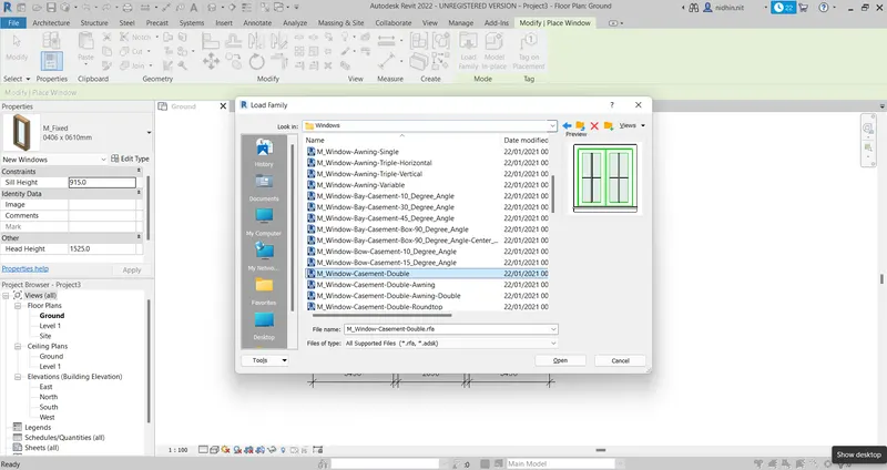
- Click on the load family option
- Select the residential model elements from the category folders and click open
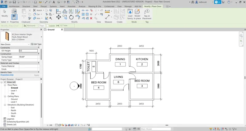
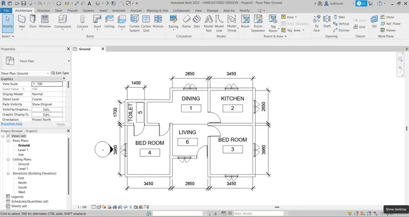
- Select the size of the components and insert it into the model.
Doors:
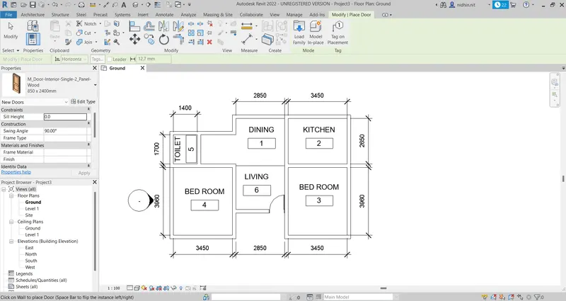
Windows:
Bed:
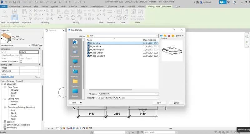
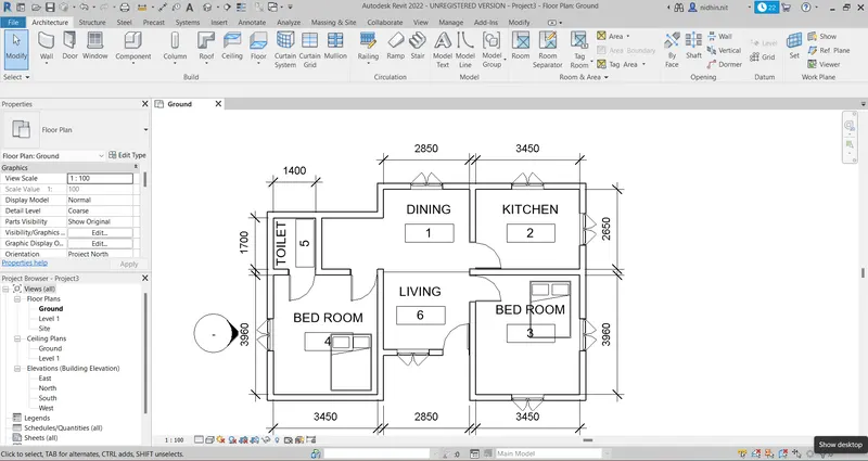
Table:
Couch:
Chair:
Lamps: