Creating Levels, Grids, Layout and model elements for a residential unit using REVIT
1)
- BIM refers to Building information Modeling. BIM is a concept that was invoked by the Autodesk .
It mostly about the information . Which helps us in making efficient planning, desing, construction and manage building and infrastructure . BIM involves many tools like Revit for acheving the process. BIM is a place where the Architecture, engineering, construction proffesional collabrate threr work and use tools to effectively model the project.
FEATURES OF BIM
These are the following features of BIM
Co-ordination:It helps us in coordination between different disiplanes of work like architectural,structural and mechanical to work as a whole unit.
Computation:helps in performing computation such as material schedules, Quantity schedule etc.
Import the 2D models
Create 3D modelling
Building Optimization
Easy access to information
It gives more comprehensive overview of the project . It covers every component of this process from geometrical aspect of the design to spacial relationships.Provide tools for different disiplanes like Architectural,plumbing,structural and so on. Locating the location
BENIFITS OF USING BIM OVER 2D CAD TOOLS
a. Minimize the time for completion of project.
b. when we make changes in model it refelects the real time changes in the elevationview,paperspace,draftingviews.
c. Reflect changes in real time basis.
d. Better collobration and computation.
e. Model based cost estimation.
f. It helps us to visualize the project.
g. Conflict detection and Risk mitigation.
2)
Understanding the cincept of Categories, Families, Elements, Instances in Revit.
Categories: They are predefined already in the Revit. These consist of elements that share a common prpoerites. and they cannot be further added that share a commom praperties. And they cannot be further added or deleted or renamed.
The following are the categoies.

FAMILIES: Families are which shares a group of elements that shares acommon properties. Lik ethe DOOR is a category which consists of family of single flush where we can see elements of diffent sizze doors.
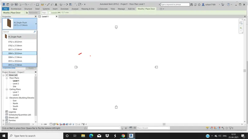
ELEMENTS: Any thing in the Revit is an Element.
INSTANCES: Prameter ensbles us to modify the parameter value separately foe every instance.
AIM: To understand the instance and insert it in to the Revit model.
TOOLS USED: Load family
PROCEDURE:
1. Select the Inset tab and choose the Load family, a dialogue box appers , then go to libraries.
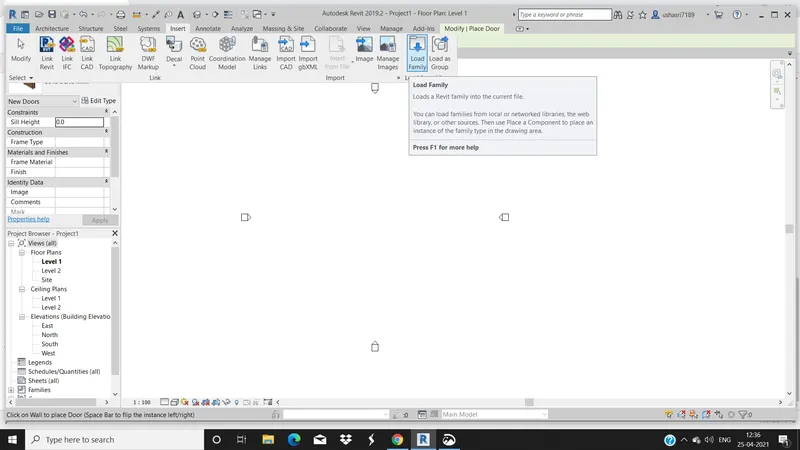
2. Select the element from the family and then click open . And place the element in requied positon.
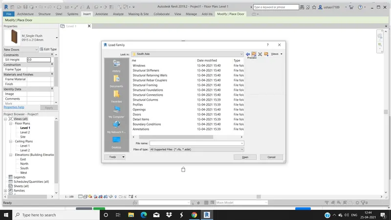
RESULT: The concezzts of Categeries, Family, Elements and Instances in the Revit are Understood.
3) To setup a project with Architecture template and saving the project with Archtitecture template and saving the project with aprropriate name and setting up the projects units and completing the projects information and to set maximum backups upto 3.
TOOLS USED:
- file
- manage
- project units
- project information
- save as
- new
- Architecture template
PROCEDURE:
1. Click on file , select new, and click on project.
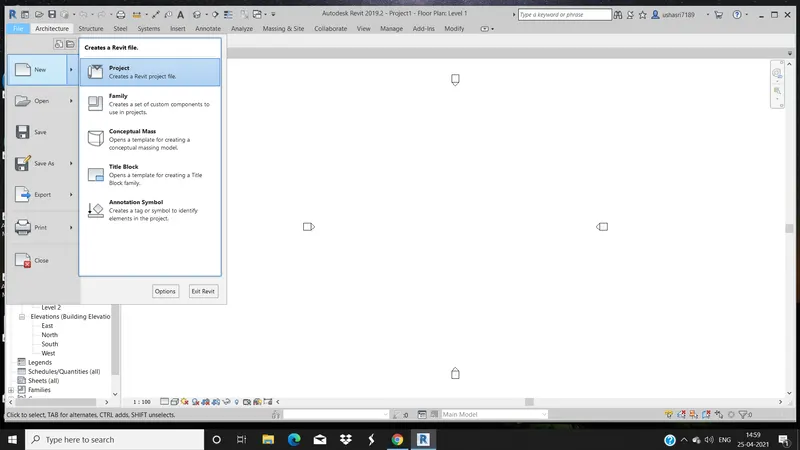
2. new project dialogue box appers select the Architexture and click ok.
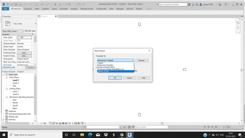
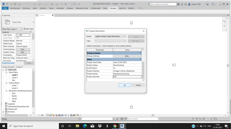
3. click on manage toolbar and select the project information, then fill the all the information like project issues, project date, project status ect, click ok.
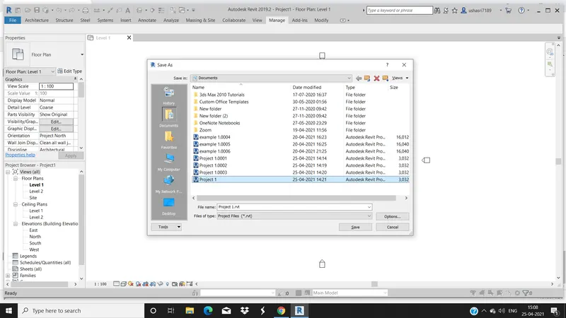
4. select the file tab, then select the save as and give file name.
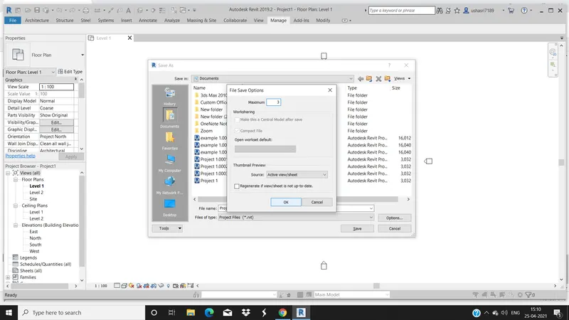
5.go to option file , then select save option anf enter the maximum files to be saved lets say 3
6. go to manage toolbar , then select porject units a dialogue box will apper and change the units as Imprial or Metric and click ok.
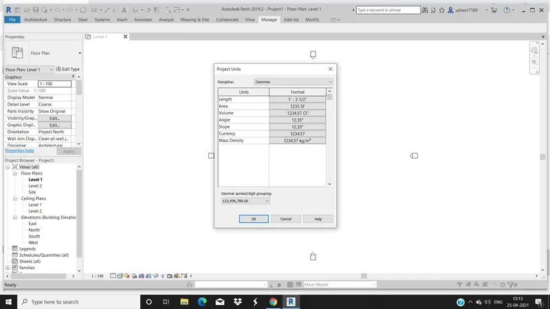
RESULT: The new project is created and save and maximum backups are kept as 3 and the project information is filled and the units of the project is changes successfully.
4)
AIM: To create the levels and Naming them as GroungFloor @0', First floor @0', Second Floor @ 20', Roof @30'.
TOOLS USED:
- New
- architecture
- view
- elevation
- East
PROCEDURE:
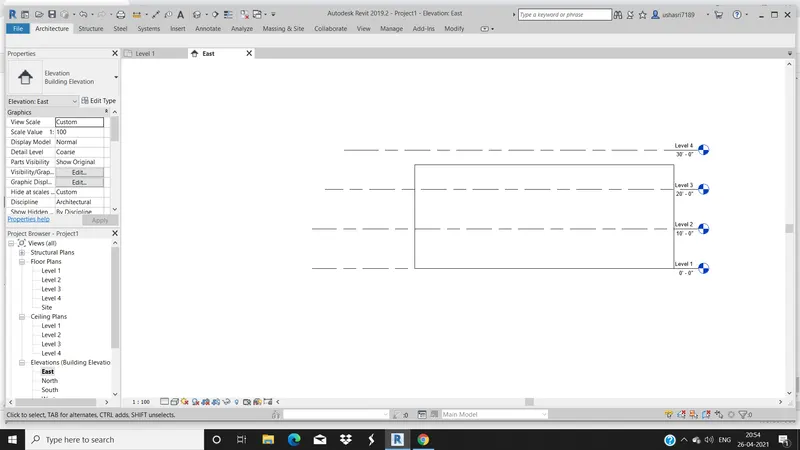
1. Go to view tab, select East in Elevation in properties browser.
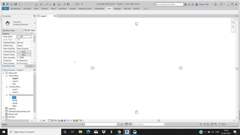
2. You can able to see the levels on the model space. as show in below.
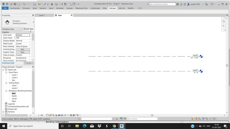
3. Click on levels which is present in the in the Architecture tab and add another levels upto required by maintaing the offset as 10'.
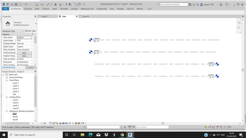
4. Rename the levels by clicking on the level-1 and name it as Ground floor and name the diffent levels as required.
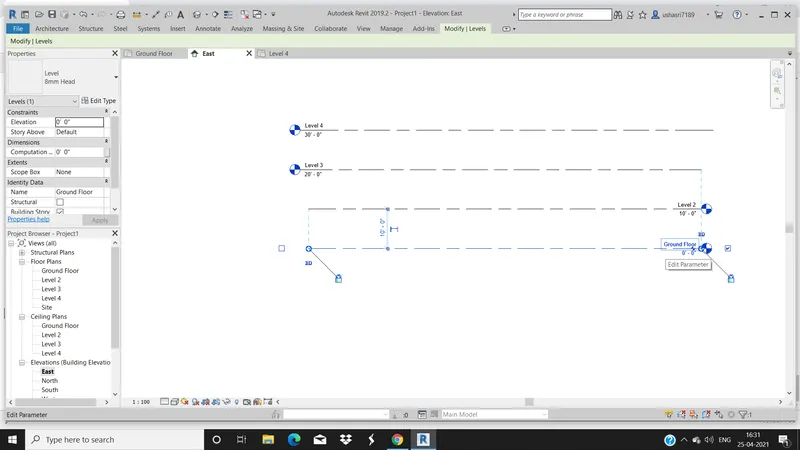
5. we can distance between the levels directly by giving click on readings.
RESULT: The different levels are create and named successfully.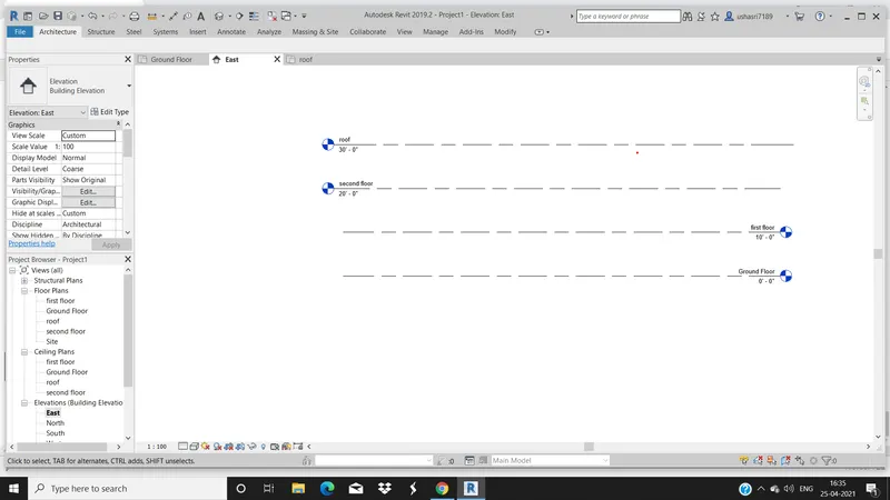
B)
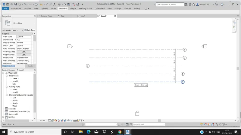
AIM: To create Tranverse Grids A,B,C,D,E @10' spacing and LongitudinalGrids from 1-10 @20' spacing
TOOLS USED:
- Architecture Template
- Arichitechure
- Grid
PROCEDURE:
1. Select Architecture tab, you will find a Grid option on the top right conrned select it,
2.Draw the Travese Grid with 10' spacing and name the Grid as A,B,C,D,E
Note: The naming should be done from top to bottom when we are nameing a Transverse Grid.
3. Now draw the longitudinal grid lines and name them from 1-10 @ 20' spacing.
Note: Naming for the longitudinal grid should be done from right to left
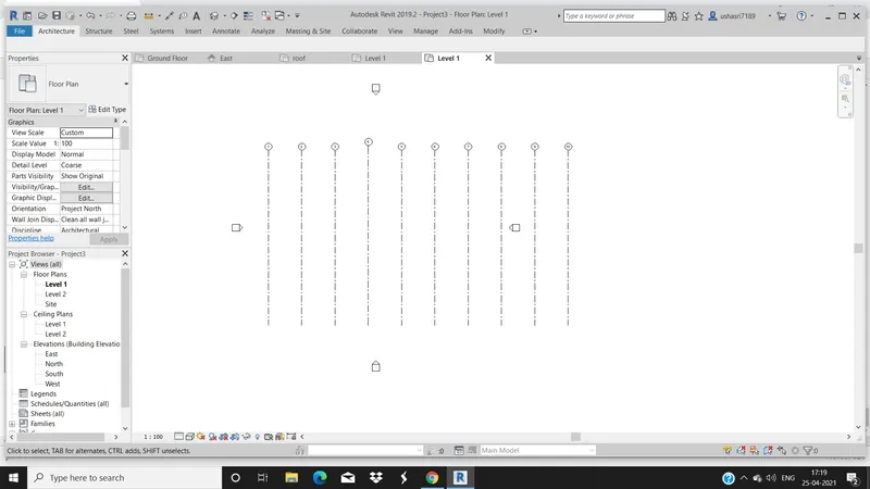
RESULT:The Longitudinal and Traverse grids are drawn and named successfully.
5)
AIM: To create a conceptual layout of the 3D modelling of residential unit.
TOOLS USED:
- open
- architecture
- wall
- properties
- edit type
PROCEDURE:
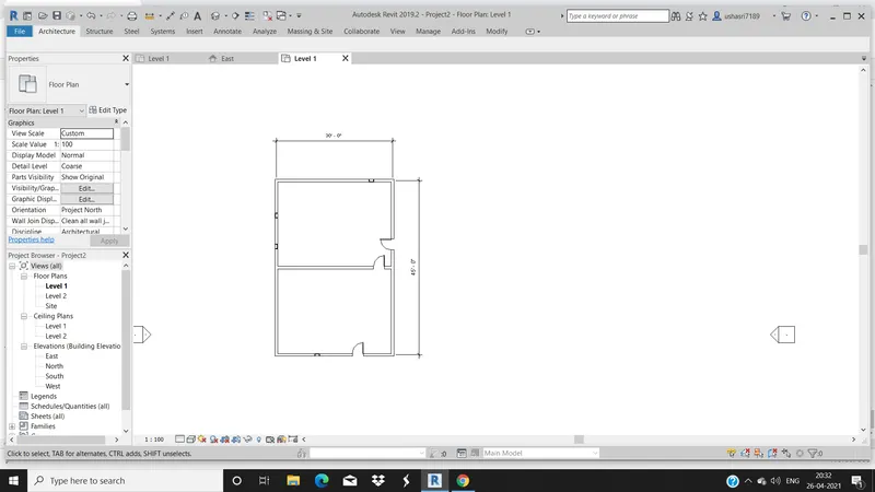
1. Click on Architectural tab and select walls and draw walls as required.
2. now go to view and select 3D view.
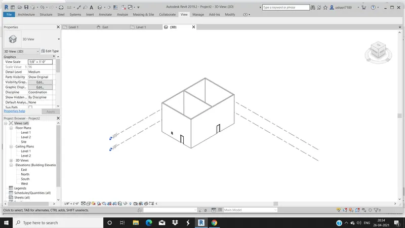
RESULT:A 30'*45' layout of Residential building is successfully created.
6)
AIM: To draft levels of details and adding dimenstions of the room and components.
TOOLS USED:
- Architechture
- walls
- annotate
- aligned
- viewroom
PROCEDURE:
1. After creating the layout , go to the properties browser and select the EAST and keep levels height as required.
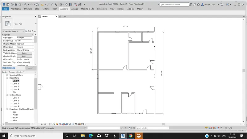
2. Then, select Architecture wall, and draw the partition walls and click on Annotate, align the dimensions to the plan.
3. Select Architecture and go to ROOM option and add rooms to the plan name the rooms as required.
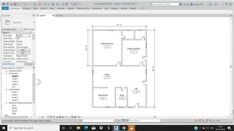
RESULT: Layout is levelled and Dimensioning is done by using align and the components of the rooms are also dimensioned and rooms are located by using room option successfully.
7)
AIM: To Identify the Residential model elements such as Doors, windows, Tables, Chairs, Couch, Bed, Lamps from the labrary and Insert them to the model .
TOOLS USED:
- Insert
- Load family
PROCEDURE:
1. After layout is created , go to the Architecture tab, then select components and place them ,
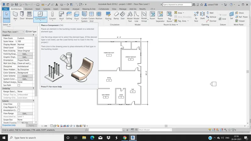
2. Se;ect the view tab and open the 3D Default view,
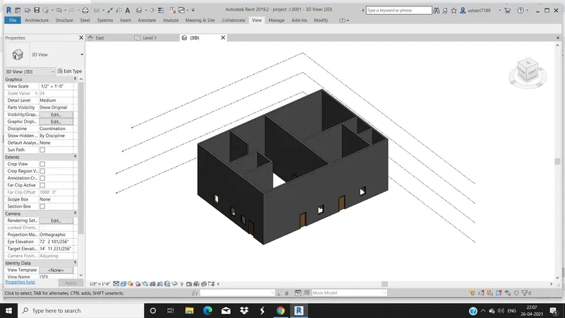
3.select the file and saveas and save the file with suitable name.
RESULT: The model elements are ideantified from the library and inserted them to the model . The project is successfully saved for further use.