Creating Levels, Grids, Layout and model elements for a residential unit using REVIT
1) What is BIM? Summarize the features of BIM and benefits of using BIM over 2D CAD tools.
Aim : To describe the BIM as a process, its features and benefits using BIM over 2D CAD tools.
Introduction :
- BIM is a concept invoked by the Autodesk and Revit is a software or modelling tool that help to achieve that process.
- BIM mainly consists of the 3D modelling concept.
- This technology allows members of project of different disciplines to work simultaneously having the different geographical location.
Procedure :
BIM concept
- BIM is process of creating structural, multidisciplinary data to produce digital representation of an asset across its lifecycle from planning to construction operation.
- BIM is visual representation of physical and functional characteristics of the facility from inception onwards.
- BIM consists of 3D modelling concept in addition to building information database technology which allows members of the project to generate virtual model of the structure and all of its systems in 3D and to be able to share information toe each other.
- BIM is divided into two core concept
- Coordination
- Computation
Coordination :
- It helps in achieving coordination between multiple disciplines such as architect, mechanical and structural engineers.
- It is able to work on same project from different geographical location to work on single project simultaneously.
Computation :
- Computation helps to obtain the material schedules or quantity schedule or to perform the energy analysis.
- Different tool associated with the Revit such as structural disciplines has Robo-structure analysis that helps in computing response to the loads that is applied to the buildings.
Features of BIM
1.acess to information :
- It is a visual representation of physical and functional characteristics of the project that provides very minute details of the project.
2.making of process more expressive:
- It allows to work accurately in 3 dimensions i.e., length, breath and height. However BIM modelling services allow to work in 5 dimensions i.e., time and cost in addition to length, breath and height. Therefore it is able to produce accurate material and cost estimate, pre-size time schedule of project even as design is being developed.
3.comprehensive view of project :
- BIM model not only presents 3D geometric view of the structure they provide more comprehensive google view of entire building process.
- It covers every component of process from geometric aspect of design to special relationship from light analysis to provision of various services, topographical information etc.
Benefits of BIM
Main benefits of BIM over 2D CAD tool is that in 2D CAD tool if we want to make the changes in plan then that changes are not interpreted in the elevation but in case of BIM the change in plan is interpreted automatically in the elevation also.
1.complete representation of building design
- It takes into account minute details of building e.g., BIM allows to design electrical system as well as building itself.
2.Instant updates
- BIM allows instant update of all the components of building.
3.Time constrains
- It is able to prefabricate important component of building ahead of time instead of adjusting such components based on building design.
4.Resource tracking
- It is possible to update the model constantly as per the work of the project.
- Also it allows client to check the project at any time which leads to quick approval for milestone and more efficient project development.
- It will be able to figure out resource needed during the design process which improves flow and efficiency of construction.
Result :
Hence the concept of BIM , its features and benefits are explained above.
2) Understand the concept of Categories, Families, Elements, Instances in Revit. Go to Insert Tab, choose a category. Pick a family and element. Understand the instances and insert it to Revit model
Aim : To understand the concept of Category, family, Element, Instances in Revit and insert the instances in the Revit model in Revit software.
Introduction :
- Revit offers huge database of components that adds details to the project and these elements are called as categories and families.
- We can add minute details in the Revit model using the insert tab and make it more realistic to visualize the space utilization of the model.
Procedure :
Category :
- Category is the properties in the rivet that are already present or predefined by software.
- Examples of the category are wall, Doors, Windows, Floors in the Revit software constitute the categories in the Revit software.
- we can insert new category of our own and define the element of our choice under particular category.
Families
- Group of elements that share a common property is called the family.
- Example if door is the category then single flush door is the family.
Type
- Specific representation in family defined by direct parameters, graphical and documentation characteristics which make it unique from other types in the family.
Instances / elements
- Individual representation of a type in project defined by unique parametric, graphical and characteristics which make it unique from other instances in the project.
To add instances in Revit model
- Go to architecture tab, select the door from build panel, select load family from mode panel it will open library dialog box.
- Select English-Imperial from dialog box and select open it will open the category dialog box as shown below.
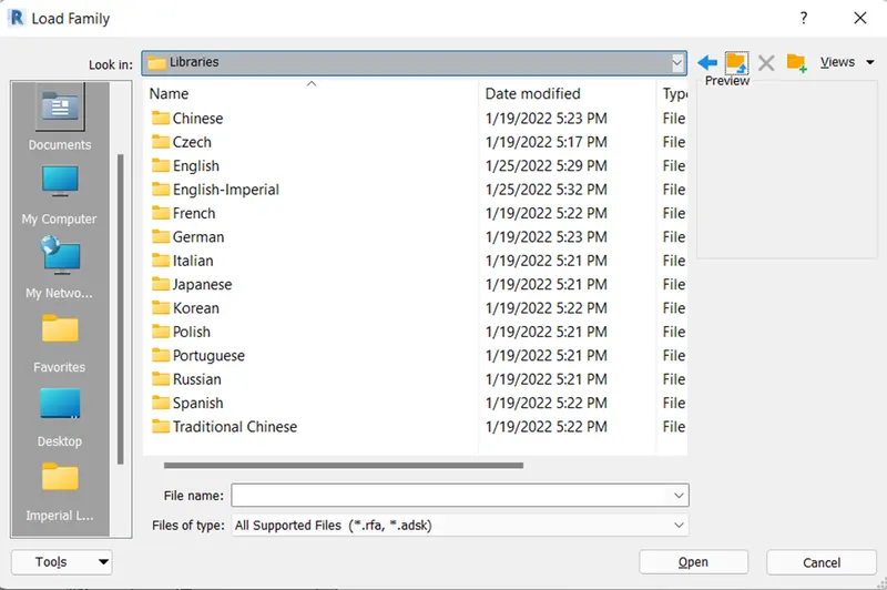
- Select the doors category from dialog box and select open from dialog box.
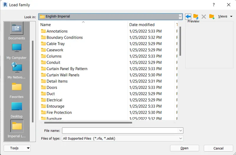
- Select the residential family from dialog box and select open option.
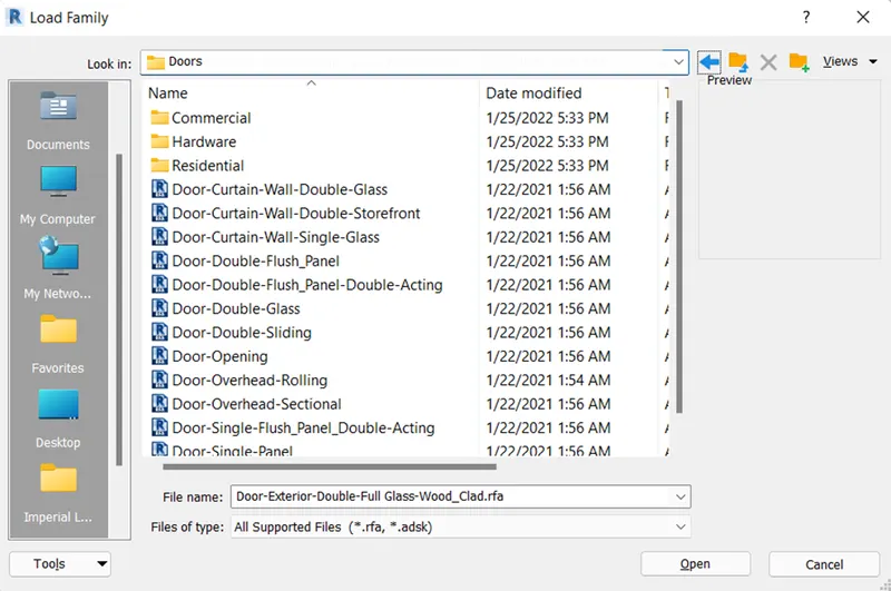
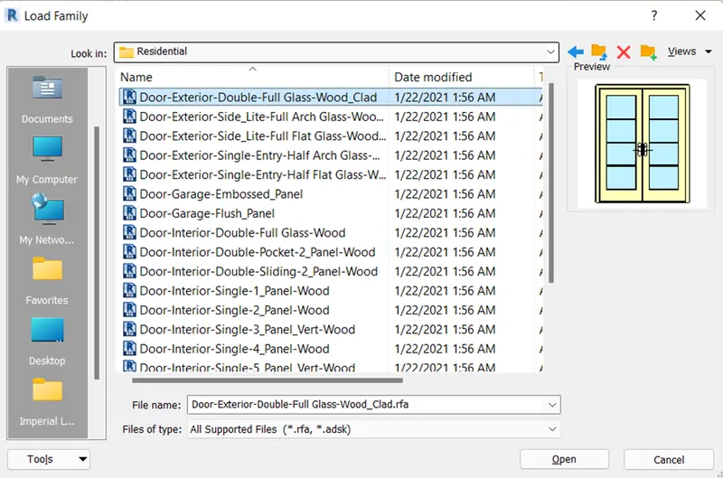
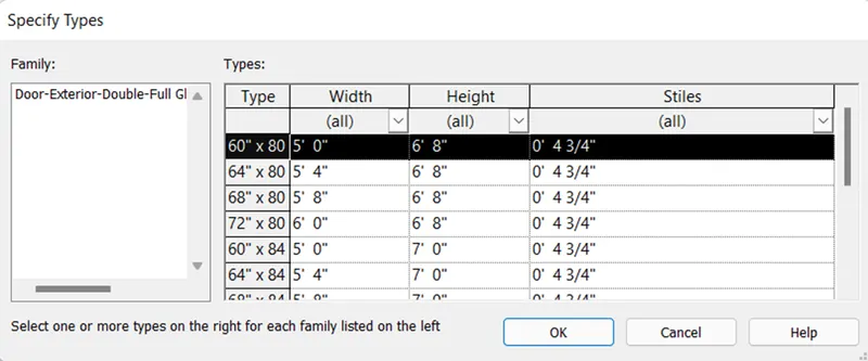
- Select the door-exterior-double-full Glass-Wood_ Clad option from dialog box and select specific type as 60” x 80” and select ok.
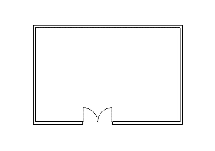
- Add the door at existing Revit model at the appropriate position as shown below.
Result :
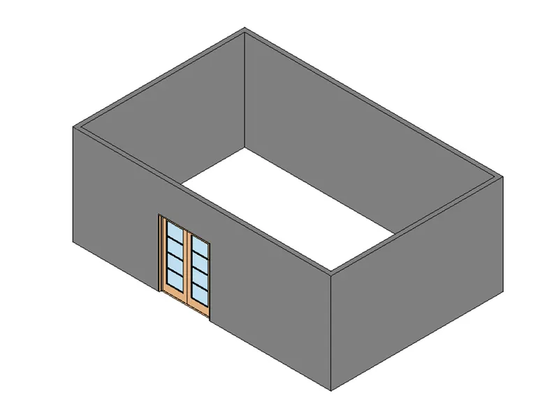
Concept of category, families, elements, instances in Revit are understood and successfully inserted in existing Revit model by following above mentioned procedure as shown below.
Floor Plan
3D view
3) Setting up a Project – Open a project file with architectural template. Save the file with appropriate name. set up the project units to imperial / metric based on your convenience of modelling. Complete the project information under Manage tab. Set up the maximum backup for project file to 3.
Aim : To set up a project by opening a project file with architectural template and save it with appropriate name in the Revit software by setting maximum backup for project file to 3.
Introduction :
- In the Revit software project is created with different template such as architectural, structural, construction and system template.
- The project information is added using the project information tool which can be seen in sheets of model.
- In Revit software we can set maximum backup project files from 1 to 99.
Procedure :
- Open the Rivet software.
- Select the new option from the home page of the Rivet software.
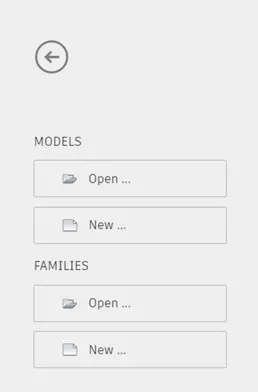
- By selecting new option it will open the new project dialog box as shown below.
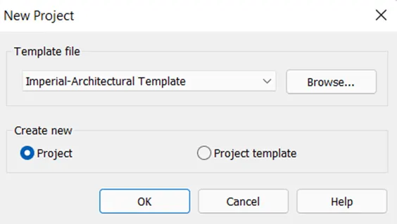
- Select the template file as Imperial- Architectural Template from dialog box, and select ok it will open the Rivet window.
- Click on the file tab of toolbar and click on Save as drop down, it will open the file dialog box.
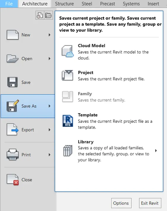
- Select the Project option to save the current project file, it will open the Save As dialog box as shown below.
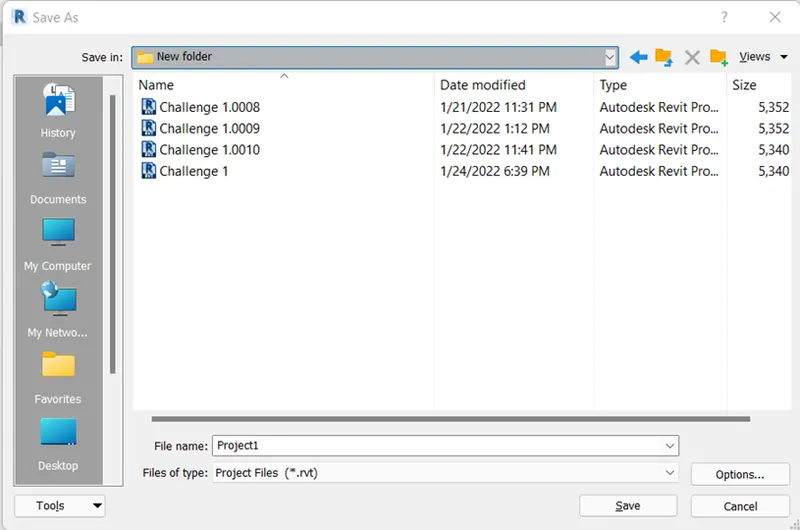
- From the dialog box, change the file name as Challenge 2 and select the Save option it will save the file as Challenge 2.
- From the Revit window, click on the Manage tab.
- From the manage tab select project information icon from setting panel.
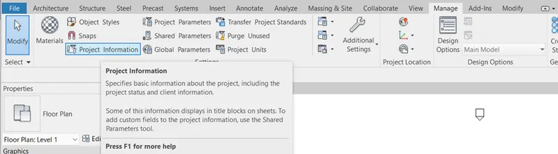
- After selecting project information it will open the project information dialog box.
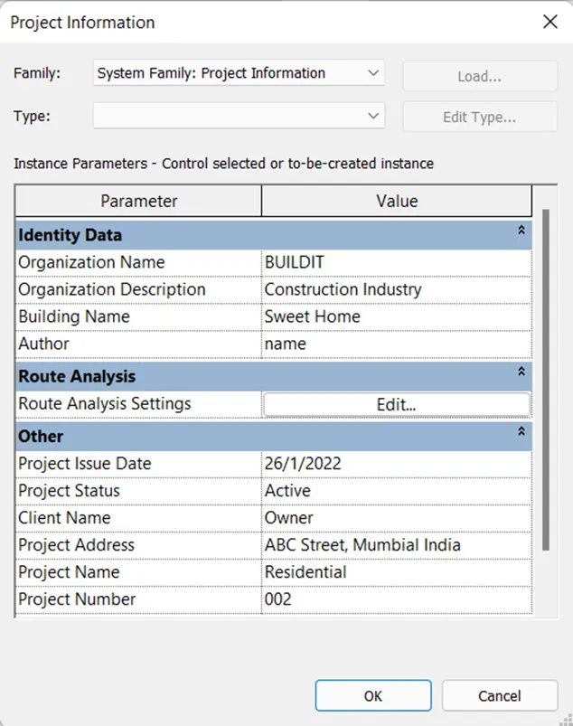
- Complete the project information such as organization name as per our choice say BUILDIT, organization description as Construction Industry, building name as Sweet home, project issue date as 26/1/2022, project status as Active, client name, project name as Residential, project number as 002.
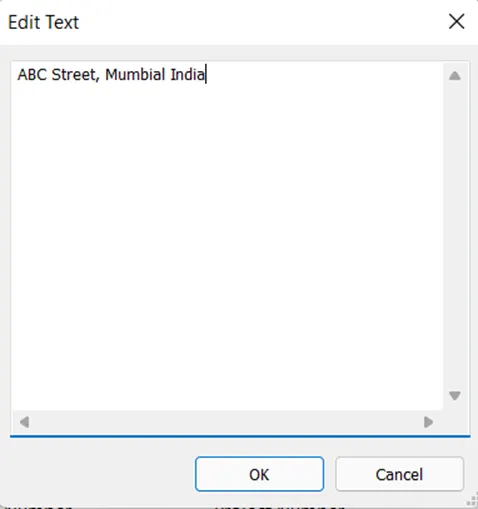
- For giving the project address click on dots beside the project address and type the project address as shown below in edit text dialog box as shown below.
- The project information is set as shown below and select ok.
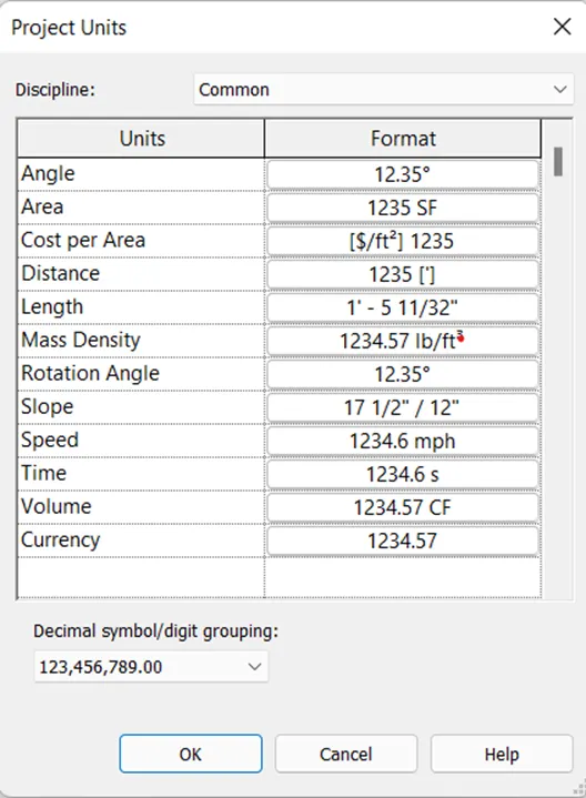
Type UN and set the units from dialog box as shown below and select ok.
- Once again, select file tab and go to save as option.
- Select project option as mentioned above, and choose option from Save As dialog box, it will open the file save options dialog box.
- Set the maximum backup for project file as 3 as shown below and select ok.
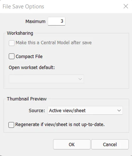
- Select the save option form Save As dialog box.
Result :
Therefore project is set up with project unit as imperial and project information is completed with maximum backups for project file to 3 in Revit software by using above mentioned procedure.
4) Understand the concept of Levels and Grids. Follow the naming and conventions. Create the following Levels: ( Convert to metric equivalents if metric is your units)
Ground Floor @ 0’
First Floor @ 10’
Second Floor @ 20’
Roof @ 30’
Grids Transverse Grids A, B,C,D, E @ 10’ spacing
Longitudinal Grids from 1 to 10 @ 20’ spacing
Aim : To create the levels at required elevation from datum and grids at the given spacing in Revit software.
Introduction :
- Levels acts as references to measure the elevations of different components of building and can be seen in the elevation view.
- Grids acts as references to measure the horizontal distances of various components of building to locate the building components.
- Grids can be seen in the floor plan views,
Procedure :
- Open the Revit software.
- Select the challenge 2 file to open the file.
- From the property browser window, double click on the East option of elevation menu.
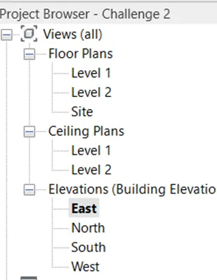
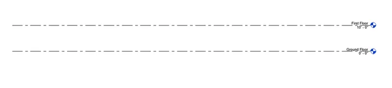
- It will open the elevation showing two level lines as shown below.
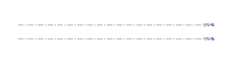
- Select the 0’0” elevation line , click on the name box of level line and change the text as Ground Floor press enter and conform the level rename by selecting yes from conform level rename dialog box.
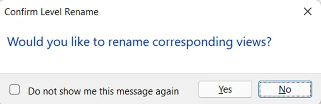
- Similarly click on the upper level line it will turn into blue, click on the name box of level line and edit the name as First Floor and press enter as shown below.
- As the ground floor level and first floor levels are already at their desired levels there is no need to change the level height.
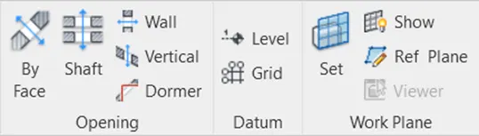
- Click on the Architectural tab of toolbar and select the level tool from the datum panel.
- From the modify/place datum tab select the pick line icon from draw panel.
- Change the offset distance as 10’0”.
- Click on the ground floor level line to add upper level second floor at offset of 10’0”.
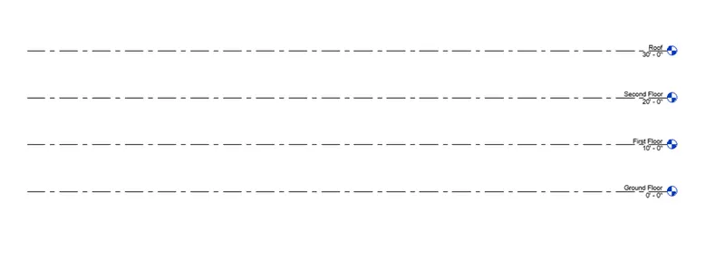
- Similarly click on the just created level line to add level line as a roof at offset of 10’0” in upper direction.
- First select the just created first level line and click on the text box to change name of level line as Second Floor and press enter.
- To change the name of fourth level line firstly select the uppermost level line and click on text box and change the name as Roof and press enter which is at a height of 30’ from the datum line as shown below.
- For creating the grids double click on the first floor option of floor plan list of property browser it will open the first floor plan.
- Select the Architectural tab from toolbar, in that select Grids option from datum panel.
- From modify /place grid tab select the line icon of draw panel and draw the first grid line starting from left to right as shown below.
- Select the pick line icon from draw panel, change the offset distance as 10’0”, press enter and select the first grid line to draw the other grid in downward direction.
- Again, select the just drawn grid line and draw the third grid line in downward direction.
- Similarly create the two other grid lines in downward direction and press esc.
- To edit the names of grid, select the first grid line, click on text dialog box and edit the text as A and press enter.
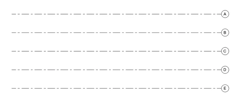
- Similarly rename the other grid lines as B, C, D and E respectively as per their sequential order as shown below.
- To draw the longitudinal grid lines from 1 to 10 from Architectural tab select the grid option from datum panel.
- Select the line option from the draw panel and draw the vertical grid line from top to bottom and press esc.
- Again go to architectural tab, select the grid option from datum tab, select the pick line icon from the draw panel, change the offset distance as 20’0”, press enter, select the first grid line and draw the another eight grid lines by following the same procedure.
- To edit the names of grid, select the first longitudinal grid line, click on text dialog box and edit the text as 1 and press enter.
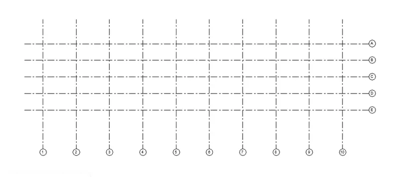
- Similarly rename the other grid lines as from 2 to 10 as per their sequential order as shown below.
Result :
The transverse Grids A, B, C, D, E @ 10’ spacing is created in Revit software as shown below.
Longitudinal grids 1 to 10 is created in Revit software using above mentioned procedure as shown below.
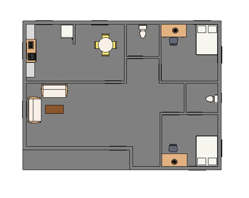
5) 3D modelling of residential unit – From looking at your house / or a place you aspire. Create a conceptual layout of the residential unit. You can measure using a tape or you can access your residential plan to create a similar layout.
Aim : To create a conceptual layout of the residential unit or 3D modelling of residential unit.
Introduction :
- Before modelling the residential unit we should know the orientation of the building to ensure the proper ventilation and lighting aspect of the building to utilize maximum amount of natural resources.
- We should also consider the space constrain of the building before creating the layout of the building.
- After fixing the orientation and layout of building we will model the residential unit by following the below mentioned procedure.
Procedure :
- Open the Rivet software, double click on screen to open the file menu.
- Select the new option from model menu of home page of Revit, select the Imperial-Architectural Template and select ok.
- Click on file tab on the toolbar.
- Select the save option from the list and save the file as Residential unit 1 and select the save option to save the file.

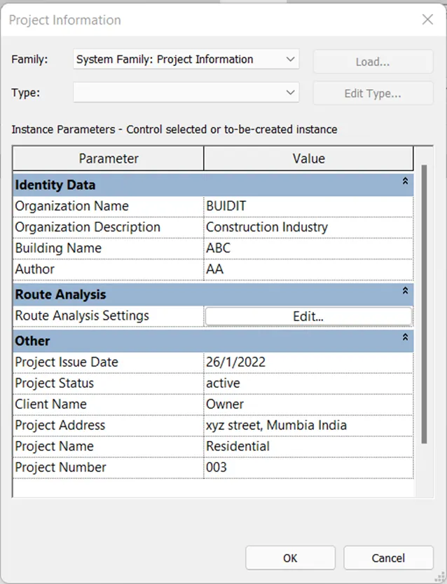
- Go to the manage tab, select the project information option from the setting panel and fill the parametric information as shown below and select ok.
- Double click on the Level 1 option from the property browser in the floor plan menu it will open the plan at level 1.
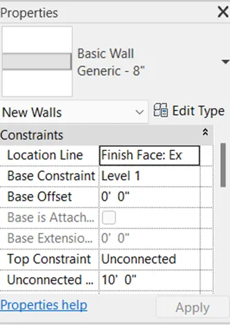
- Go to Architectural tab, select the wall tool, from property window select the wall type as basic wall Generic-8”,wall location as Finish Face Exterior as shown below.
- Modify the offset distance as 10’0”.
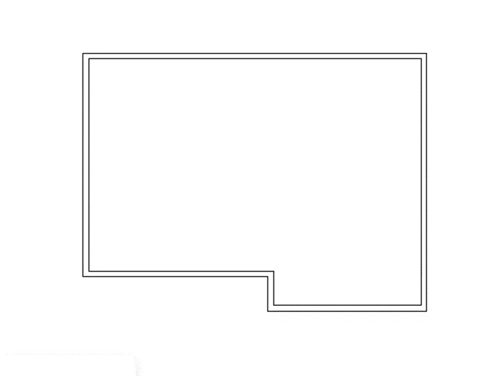
- For drawing the exterior wall click on screen to specify first point move the cursor in right direction and draw wall of length 40’.
- Move the cursor in downward direction and draw the wall of line 30’ in downward direction.
- Move the cursor in left direction and draw wall of length 18’6” by tracing it , then move the cursor in upward direction and draw the wall of 4’ length.
- Similarly by moving the cursor towards left direction draw wall having end point coinciding with line passing through start end of wall.
- Similarly draw the last wall joining the endpoint of last drawn wall and start end of first wall to close the geometry.
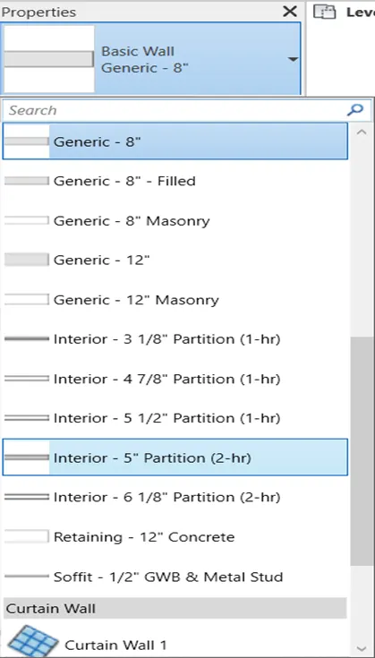
- Again, go to architectural tab, select the wall icon from build panel and choose the wall type as interior – 5” partition wall from the properties window as shown below.
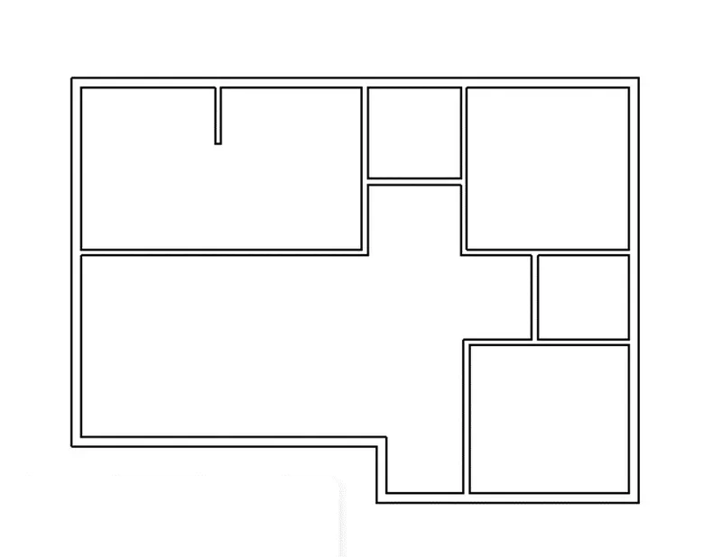
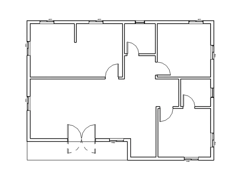
- Draw the partition walls inside the drawn exterior wall at required position having required length as shown below.
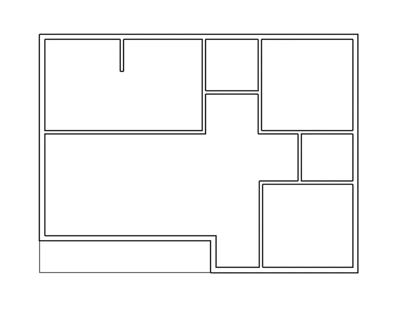
- Go to architecture tab, select the floor tool from the build panel, in that select the floor-architectural , select the rectangle icon and draw the floor by selecting first corner and opposite corner to create the rectangular floor.
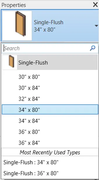
- Select the Architectural tab, select the door category from build panel, select the family as single flush and element or instance as 34” x 80” and place the door at the required position.
- Similarly insert the double flush door of size 72” x 80” for living room and door of size 30” x 80” for toilet room at the required position as shown below.
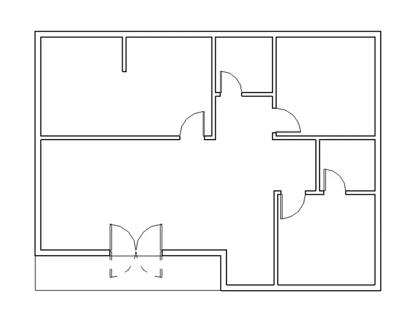
- Go to the architectural tab, select the category as window icon from the build panel.
- Go to the load family option from mode panel, select the windows category from load family dialog box, select the windows-sliding-double option from dialog box and select open option from dialog box.
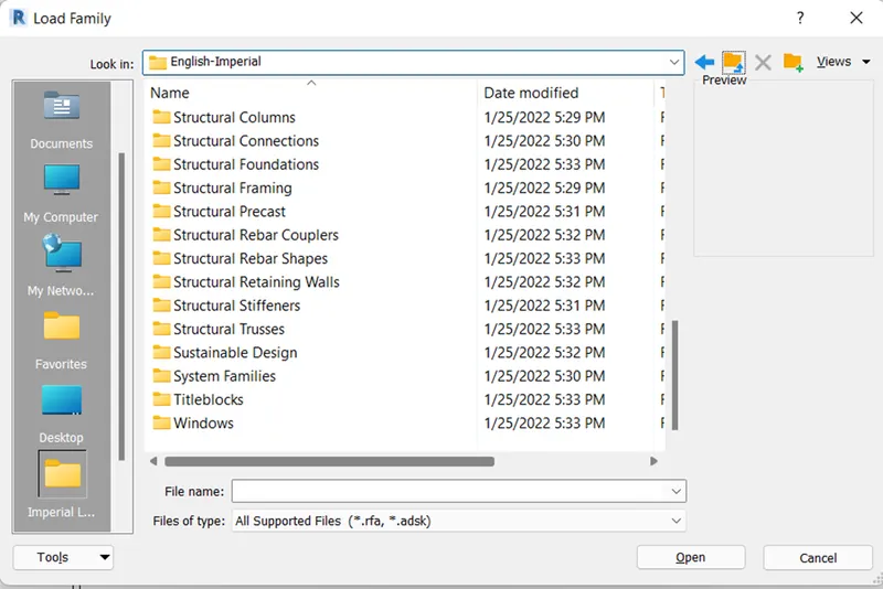
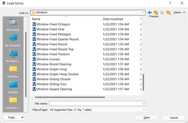
- After selecting open it will open specify types dialog box, select the type as 36” x 48” type and select ok.
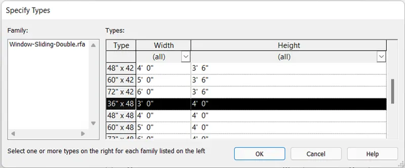
- From property window, select the family as fixed family and choose the element as 36” x 48” and insert the window at required position.
- Similarly insert the other windows at their required position as shown below.
- Similarly insert the window louvers of size 24” x 24” at the window position of toilet room.
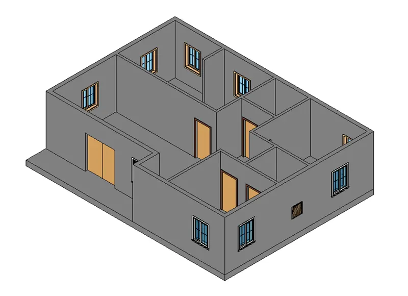
- To see the 3D view, select the 3D view option from create panel and select default 3D view option.
- From the bottom toolbar select the visual style for 3D view as consistent color to get the 3D view.
Result :
Therefore, conceptual layout of Residential unit is created in Revit software using above mentioned procedure as shown below.
Similarly consistent color 3D view of residential unit in Revit software is shown below.
6) In the layout created draft the level of details you are planning to include – Dimensions of room, components you plan to add in the residential unit.
Aim : To draft the dimensions to created layout using Revit software.
Introduction:
- Dimensions can be added in the Revit software by using the annotate tab where we can add dimensions using the linear of aligned tool.
- Linear tool is used to add vertical and horizontal dimensions whereas aligned tool is used to add dimensions along the inclined components.
Procedure :
- Open the Revit software, select the Residential unit file from file menu, it will open the Revit file and Revit window will open.
- Double click on Level 1 option from floor plan of properties window to set it as current view.
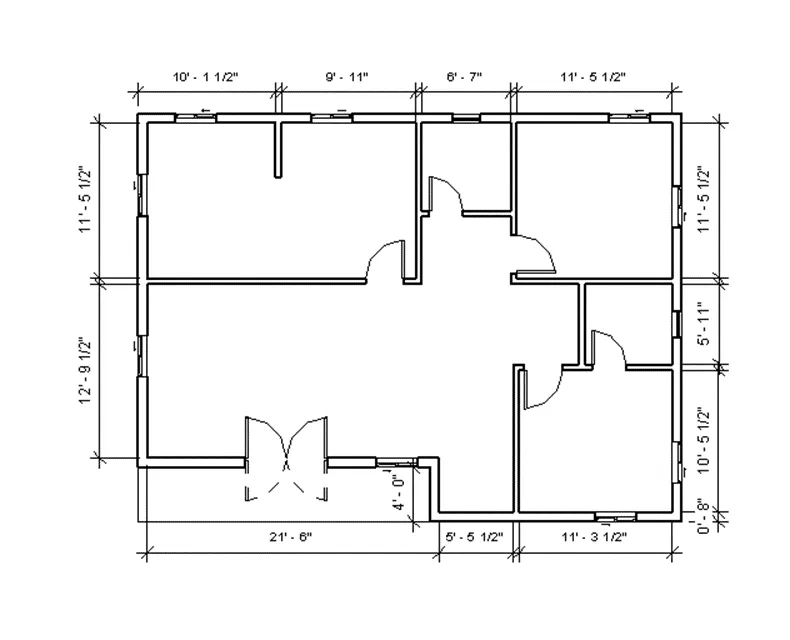
- Go to the Annotate tab of toolbar, select the linear tool from dimension panel, select the first corner of the wall and second corner of wall move the cursor in upper direction and place the dimension line at appropriate position.
- Similarly give dimensions to all other wall using linear tool of Annotate tab.
- For giving the dimensions using aligned tool, go to Annotate tab, select the Aligned tool from dimension panel, select the first endpoint as topmost end of leftmost wall and other endpoint as opposite endpoint of wall, move the cursor in left direction and place the dimension line at appropriate position as shown below.
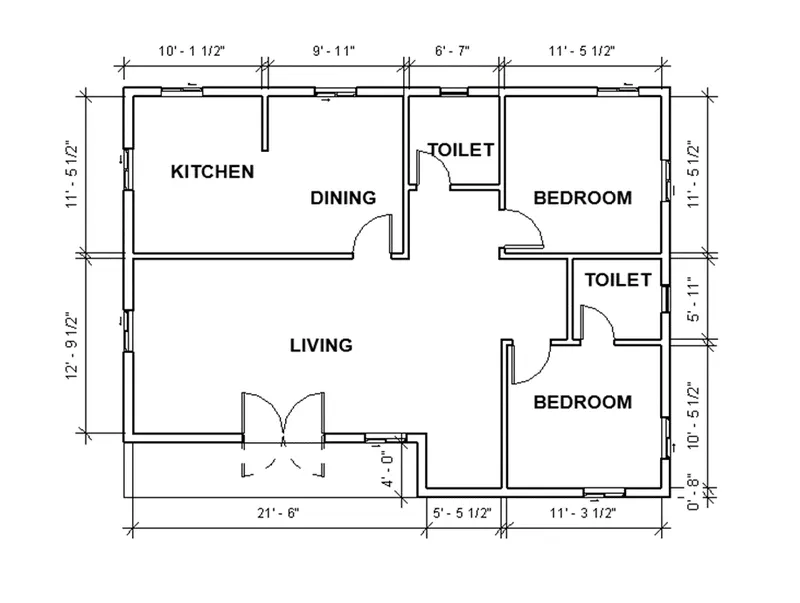
- Go to the Architecture tab, select the Room tool from Room & Area panel , select the particular room and add the tag to all the rooms and press esc.
- Select the room tag, click on text box of tag and edit the text as per requirement as shown below.
Result :
Therefore, dimensions of the room are added in the created layout using above mentioned procedure in the Revit software as shown below.
7) Identify the residential model elements such as Door, Windows, Tables, Chair, Couch, Bed, Lamps from the library and insert them to the model . Save the project for use
for Assignment 3
Aim : To identify the residential model elements such as Doors, Windows, Tables, Chair, Couch, Bed,, Lamps from library and insert them in the model in Revit software.
Introduction :
- Revit is BIM software where we can add minute details in the project which are more realistic to visualize the model.
- Various residential model elements such as doors, windows, tables, chairs, couch, bed and lamps can be added in the Rivet model.
Procedure :
- Open the Revit software, select the Residential unit file from file menu, it will open the Revit file and Revit window will open.
- Go to the architecture tab, select the component tool from build panel, select the place component option.
- To add bed ,Select the load family option from mode panel it will open the libraries dialog box,, double click on the English-Imperial option.
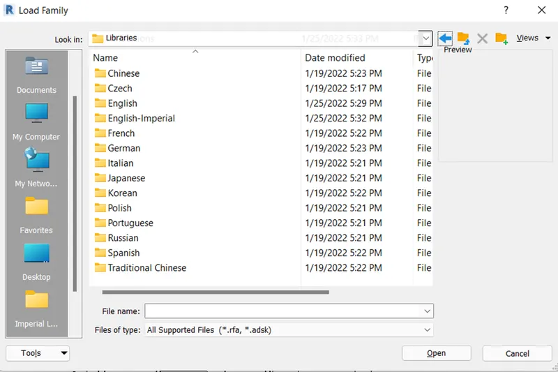
- It will open the category dialog box, select the category as furniture by double clicking on it, select open from dialog box.
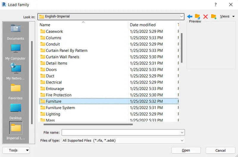
- After selecting the furniture , select the bed option from dialog box and select open.
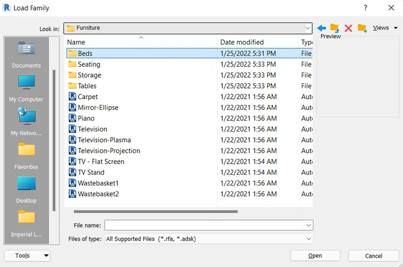
- Select the element as bed-box and select open.
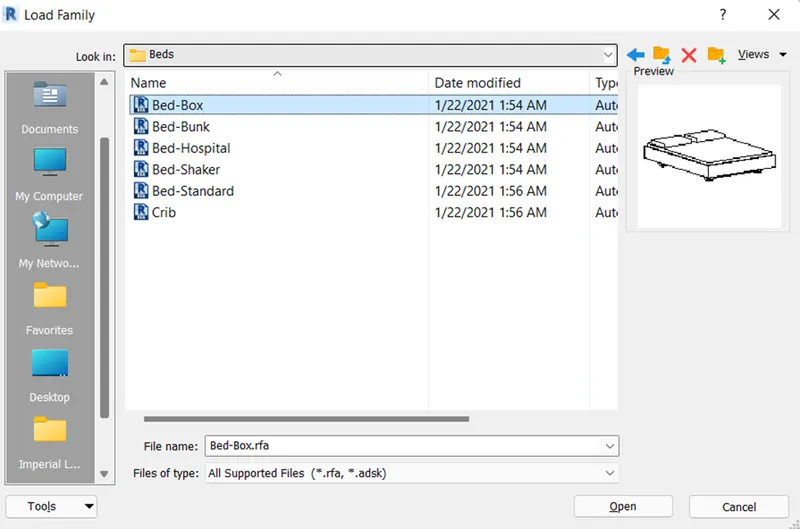
- Place the bed at required position as shown below.
- Similarly for adding the tables, go to architecture tab, select component tool, select place component option, select the load family tool from mode panel.
- It will open the library dialog box, select the Imperial English, select the furniture category, select the tables family, then select the desk instance and select open to add the component then add the component at the desired position.
- Similarly for adding the seating, go to architecture tab, select component tool, select place component option, select the load family tool from mode panel.
- It will open the library dialog box, select the Imperial English, select the furniture category, select the seating family, then select the chair-desk instance and select open to add the component then add the component at the desired position.
- For adding the Couch, go to architecture tab, select component tool, select place component option, select the load family tool from mode panel.
- Similarly for adding the tables, go to architecture tab, select component tool, select place component option, select the load family tool from mode panel.
- It will open the library dialog box, select the Imperial English, select the lighting category, select the architectural, then select the internal option, select table lamb standard and select open to add the component, from properties window change the elevation from datum as 3’ then add the component at the desired position.
- Similarly add the dinning table and table coffee mission at the desired position as shown below.
- Click on the file menu, select the Save option and save the project.
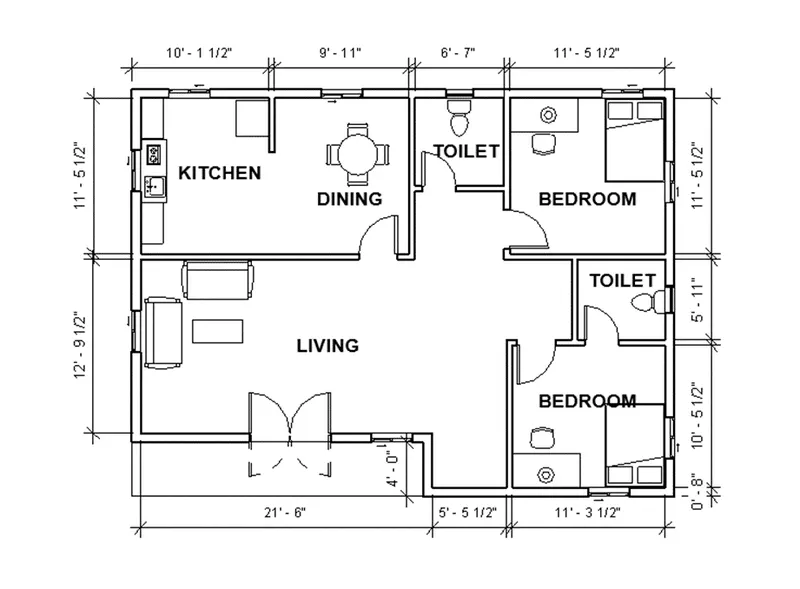
Result :
The model elements such as doors, windows, tables, chairs, Couch, Bed, and Lamps are added in the created model by using above mentioned procedure as shown below.
Floor plan view of the model
Consistent color view of the model
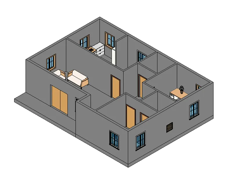
Top view