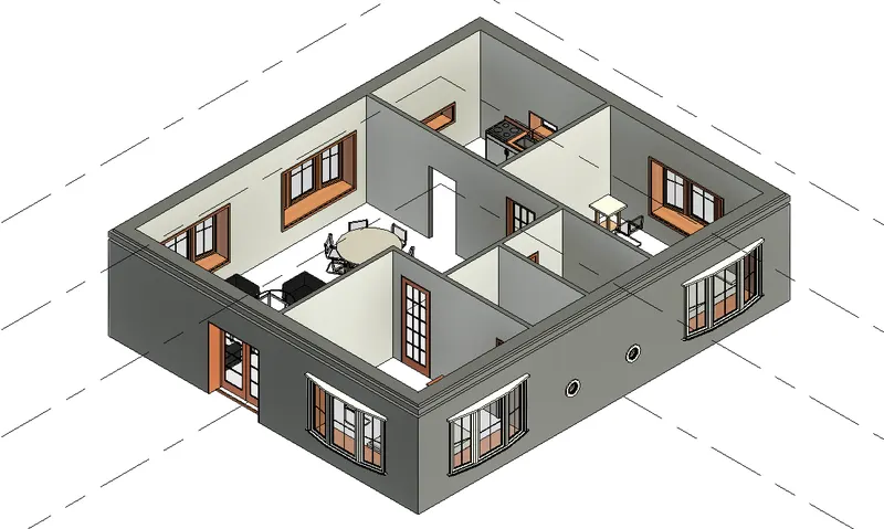
Creating Levels, Grids, Layout and model elements for a residential unit using REVIT
Creating Levels, Grids, Layout and model elements for a residential unit using REVIT
1) What is BIM? Summarize the features of BIM and benefits of using BIM over 2D CAD tools.
AIM: To Understand the BIM Process, and to summarise the features of BIM and Benefits of using BIM Over 2D CAD tools.
BIM:
Building Information Modelling (BIM) refers to the Collaborative process of generating and managing holistic information about a built asset throughout its life-cycle.BIM comprises of a suite of integrated technologies and processes that enable real time collaboration between the multiple project disciplines in an open Cloud platform, thereby aiding in Successful project delivery.REVIT is one of the tools that helps achieve BIM as a Process.
- It is a foundation for the Architecture,Engineering and Construction Industry.
- Based on an intelligent model and it is enabled by a cloud platform,BIM includes structures,multiple data to produce a digital model of an project across its lifecycle,from planing and design to construction operation.
- The goal of using a BIM Solution is to Create a 3D model that users can make changes according to requirements as its a digital representation of real life model.
- BIM offers a more Complete representation odf a building.
- BIM puts your document into a single database.
-------------------------------------------------------------------------------------------------------------------------------------------
2) Understand the concept of Categories, Families, Elements, Instances in Revit. Go to Insert Tab, choose a category. Pick a family and element. Understand the instances and insert it to Revit model.
AIM: To Understand the concept of Categories, Families, Elements in Revit.To Understand the instances and insert it to Revit model.
INTRODUCTION: The Concept of Categories, Families, Elements, Instances in Revit is explained and the procedure to access and insert the instances is illustrated.
PROCEDURE:
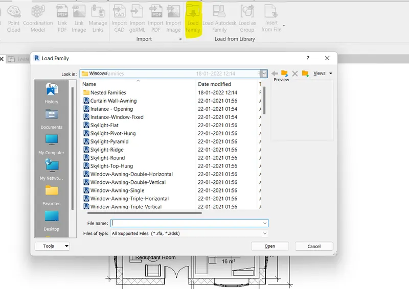
- For Loading or editing the family go to insert toolbar.
- Family is a parent block used for different objects if a change is made in the parent block then in all the predecesser items Change will be made Automatically.
- Select load family option to load family from the Component library.
- When family is loaded you can work on and edit the family part by part.
- Any single Change in the family will get Changed in all the Same items.
RESULT:
The Concept of categories, Families, Elements, Instances in Revit were Clearly Explained. It was Illustrated how to load family in Revit and Create an instance.
-------------------------------------------------------------------------------------------------------------------------------------------
3) Setting up a Project – Open a project file with architectural template. Save the file with appropriate name. Set up the project units to Imperial / Metric based on your convenience of modelling. Complete the project information under Manage tab. Set up the maximum backups for project file to 3.
AIM:To Set up a project by opening and Saving a project file with appropriate name,Setting up the project units to imperial/Metric,Completing the project information under manage tab and Setting the maximum backups for project file to 3.
INTRODUCTION: The procedure of how to Set up a project in Revit is Explained in detail and the final result is given.
PROCEDURE:
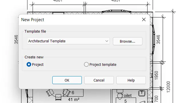
- For the above task first open the revit then go to the file Menubar and then Click on New.
- Now Select the templete as Architectural and then Set the project units to imperial.
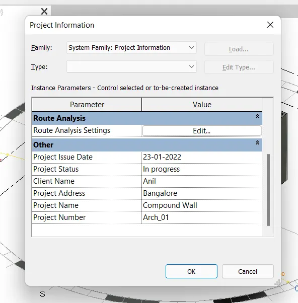
- Now for the project information go to the manage toolbar and then Select Project Information Option.
- Now enter the needed project information as follows.
- For Restriction of number of Backups for the file go to file Menu Bar.
- Now Select Saveas option and then Select project.
- Then Select option from the Appeared dialouge box.
- Then enter the number of the backups needed(3) in the pop-uped dialogue box.
- Hence the Number of backups is limited to 3 now.
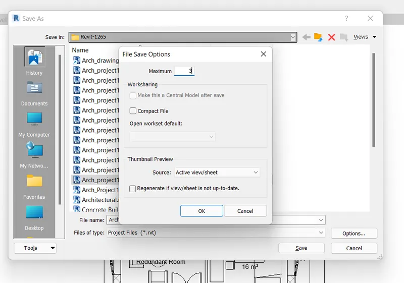
RESULT:
The Project File was Successfully Set up and the procedure illustrated Step-by-Step how to open , Save, Set the Units , Enter project information and set the maximum number of backups of the project file.
------------------------------------------------------------------------------------------------------------------------------------------
4) Understand the concept of Levels and Grids. Follow the naming and conventions. Create the following Levels: (Convert to metric equivalents if metric is your units)
Ground Floor @ 0’
First Floor @ 10’
Second Floor @ 20’
Roof @ 30’.Grids Transverse Grids A, B,C,D, E @ 10’ spacing
Longitudinal Grids from 1 to 10 @ 20’ spacing.
AIM:To Understand the Concept of levels and grids.To create the levels and grids according to that given in question following the naming and order convention.
INTRODUCTION: The Concept of levels and grids in Revit is explained and the procedure to create levels and grids in Revit following the naming and order convention is illustrated.
PROCEDURE:
- For the creation of the levels first go to any elevation Such as EAST, WEST, NORTH, SOUTH.
- Now Select the Level option from Architecture Toolbar.
- Now draw the level lines in the Elevation workplane as level indicates the different levels of the construction as ground floor , First floor, Second floor etc.
- Now as you can see the levels are created now change the name of the levels as required from the project browser.
- In the project browser there is levels now right click on each one of them and then change the name of the levels to the given name as Ground floor, First Floor,Second Floor,ETC.
- Now for the grids go to the top view on the ground floor level.
- Then Select the grid option from the Architecture Toolbar then draw the grid line of the desired length in the Workplane.
- Then draw another grid line and then copy second grid line from the base point of the first grid line.
- Numberings will be automatically given to the gridlines.
- Now try the same procedure for horizontal grid lines.
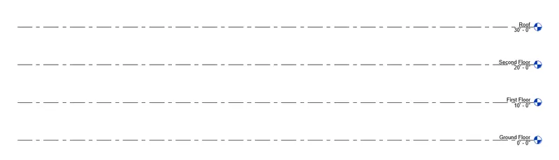
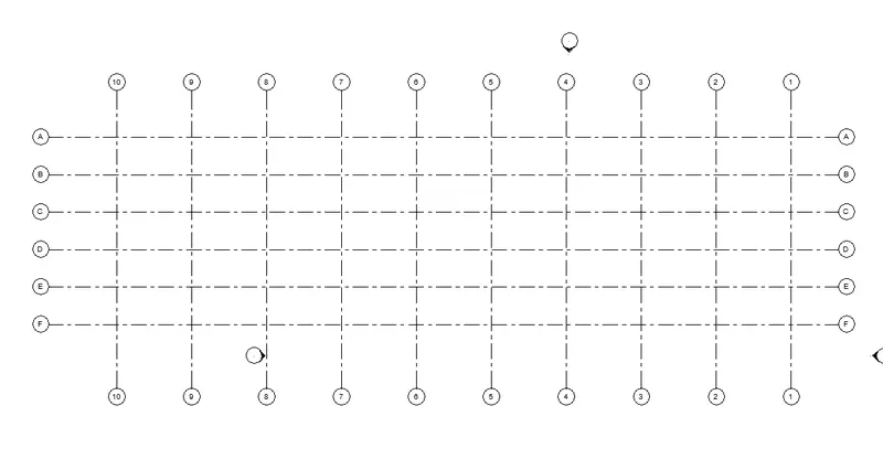
RESULT:
The Concept of levels and grids is Clearly explained. The Levels and grids were successfully created according to that given requirements following the naming and order conventions and procedure is illustrated in with detail steps.
-------------------------------------------------------------------------------------------------------------------------------------------
5) 3D modelling of residential unit – From looking at your house / or a place you aspire. Create a conceptual layout of the residential unit. You can measure using a tape or you can access your residential plan to create a similar layout.
AIM:To Create a Conceptual layout of the residential unit.
INTRODUCTION: The procedure of how to create a conceptual layout of the residential unit in revit is explained in detail and the final result is given.
PROCEDURE:
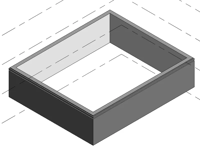
- Project Browser>Floor Plans> Ground floor.
- Select the wall tool by going to Architecture>Wall.
- From properties Select the wall type as Basic Ext. Wall.
- Specify the Location line>Finish Face: Exterior.
- Height>First Floor.
- Click at the desired start point for the wall.
- Move the Cursor towards the right hand side of the Screen and enter 10000.
- Then Move the Cursor Downwards and enter 12000.
- With the Help of tracking ,complete the remaining sides of the wall.
- Go to Annotate Tab.
- Select the Aligned Dimension tool.
- Place Dimensions:Wall Faces.
- Select the faces of the wall where the dimension is placed.
- Specify the location of the dimension line.
- Take Dimension of both the adjacent sides of the wall.
- Save the project File.
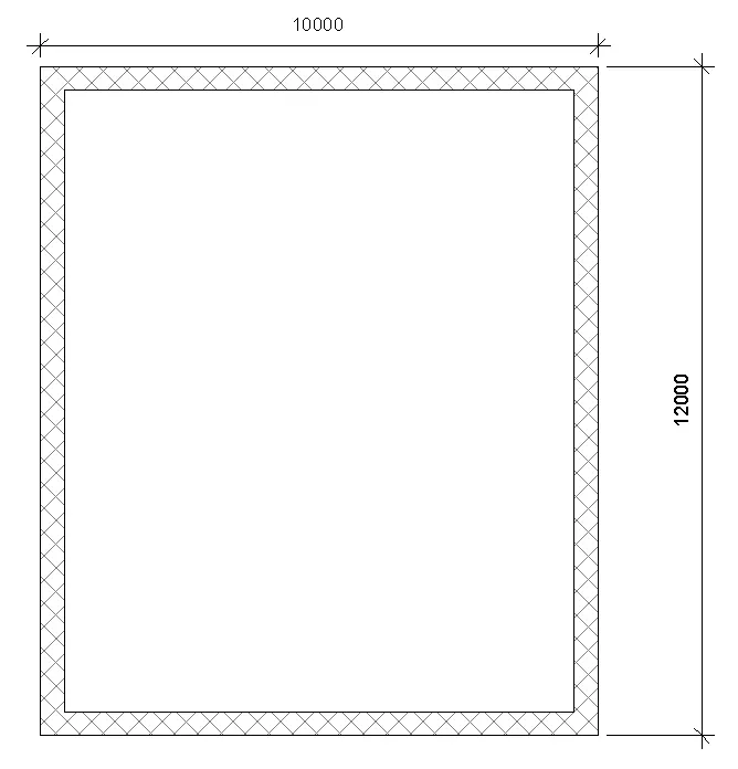
RESULT:
The Conceptual layout of the residential unit has been Successfully Created.
-----------------------------------------------------------------------------------------------------------------------------------------
6) In the layout created draft the level of details you are planning to include – Dimensions of room, components you plan to add in the residential unit.
AIM:To draft levels of details to the layout created in Q.5. To provide Dimension of room and add Components to the residential unit.
INTRODUCTION: The procedure of drafting details to the layout of a residential unit is explained by showcasing how to provide dimension of room and add Components to the Plan.
PROCEDURE:
- Project browser>Floor Plan> Ground Floor.
- Select the Wall tool by going to Architecture>Wall.
- From properties Select the Wall Type as Basic Wall int.
- Specify the Location line> Finish Face:Interior.
- Height>First Floor.
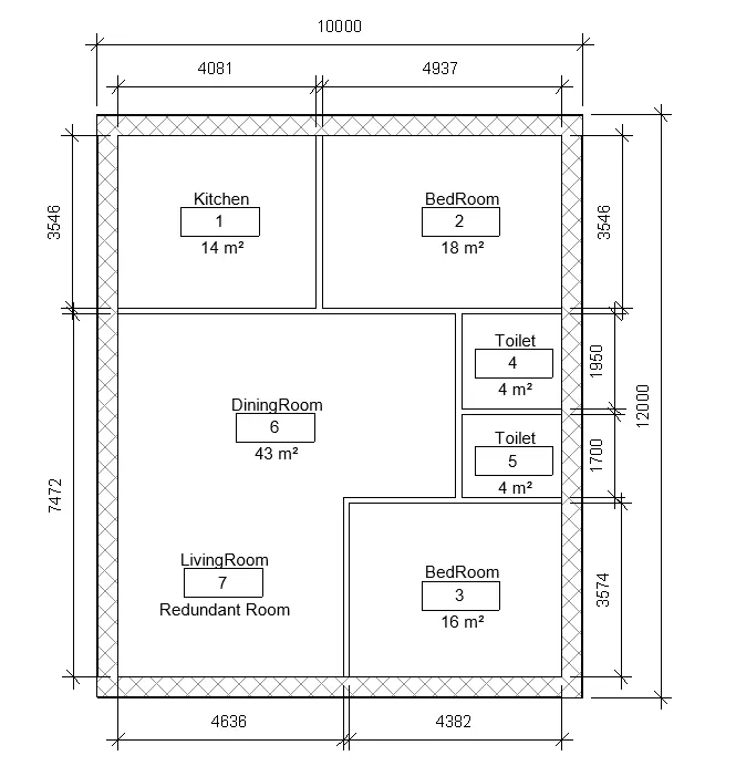
- Create the Interior Walls.
- Go to annotate tab.
- Select the Aligned Dimension tool.
- Place dimensions:Wall faces.
- Select the faces of the wall where the dimension is to be placed.
- Specify the Location of the dimension line.
- Take dimension of both the adjacent Sides of the Wall.
- Go to Architecture>Rooom.
- When dragged to the project space it automatically selects rooms based on the layout Boundary.
- Using room tool Create all specify all thre rooms in the layout.
- Using room Separator draw separation lines where no walls exists to define the rooms.
- Double Click on the room tag rename it to the Suitable denomination.
- Save the Edited project file.
RESULT:
Details Were added to the Conceptual layout of the residential unit including dimensions and sizes of all the rooms and the procedure has been clearly illustrated.
-------------------------------------------------------------------------------------------------------------------------------------------
7) Identify the residential model elements such as Door, Windows, Tables, Chair, Couch, Bed, Lamps from the library and insert them to the model . Save the project for use for Assignment 3.
AIM:To identify the residential model elements such as door,windows,Tables Chair,Couch,Bed,Lamps from the library and insert them to the model.
INTRODUCTION: The procedure of identifying elements from the library and inserting them to the model in Revit is explained in detail and the final result is given.
PROCEDURE:
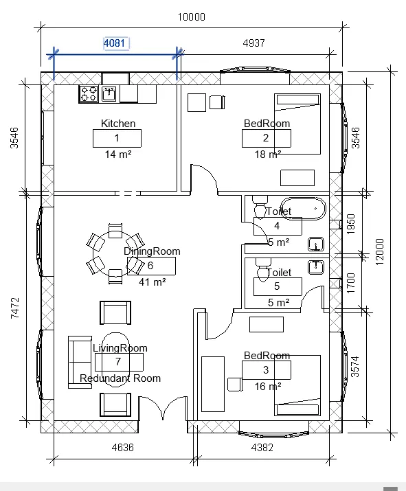
- Go to Insert>Load Family option.
- In the Load Family Dialouge box browse to the library.
- Next go to US>Windows.
- Select the desired type of the window and Click open.
- Again repeat the above process load other elements such as doors,windows, furniture,etc.
- Go to project browser Click on family.
- Click on doors ,there we can see the recently loaded Components.
- Select the element and drag it to the desired location to create a door instance.
- Repeate the Same process for creating all other instances in the model.
- Save the project.
RESULT:
Go to View>3D View.