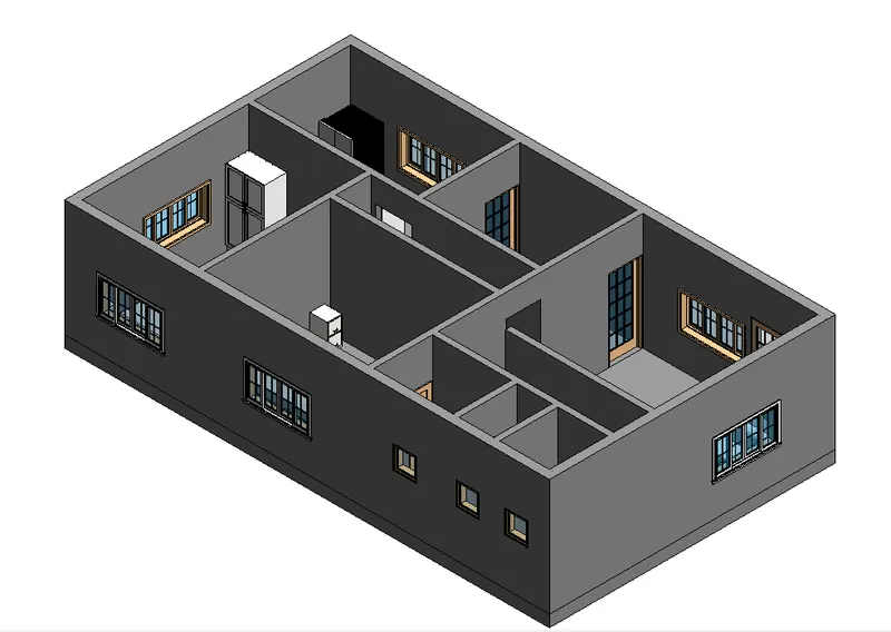
Creating Levels, Grids, Layout and model elements for a residential unit using REVIT
1) What is BIM? Summarize the features of BIM and the benefits of using BIM over 2D CAD tools.
BIM refers to "Building Information Modeling" which means documenting every piece of information related to a building project on a single platform. When we aim to start a building project, there are loads of information that shape various aspects of the building. And only as per the same information does the construction begin at the site. Primarily, the key information with respect to a building project can be listed as below:
- 2d plan
- section
- elevation
- Site Plan
- column layout plan
- beam grid
- Approval sheets
- foundation details
- 3d views
- rendered room views
- schedule of doors and windows
- schedule and quantity of materials with the current market rates
- structural analysis
- solar performance
- Energy optimization
- Wind data
- Topography features
Hence, with the introduction of Building Information Modeling, it has been made possible to build and store these details in the form of digital documents that can be printed as and when required.
Features of BIM
- Improved functionality
- Better workflow
- Time management
- Better coordination through collaboration
- Real-time updates
- Enhanced operation
- Better Analytical Approach
Benefits of Using BIM over 2D CAD Tools
- Can create and store more information in significantly less time.
- A lot easier to build and handle project details.
- Changes made to a certain detail are automatically reflected throughout the entire project which is not the case with 2d CAD tools.
- 3d view is automatically built. On the other hand, 2d CAD tools require you to spend extra time and effort in doing so.
- Real-time structural analysis can be conducted.
- The energy efficiency of the building can be examined and thus can be improved to the maximum.
- The solar perspective of the project can be precisely estimated.
- An accurate schedule of quantity with regards to the materials used in the project can be prepared simultaneously.
2) Understand the concept of Categories, Families, Elements, Instances in Revit. Go to Insert Tab, choose a category. Pick a family and element. Understand the instances and insert them into the Revit model.
In Revit, categories are divided based on the type of hardware like doors, windows, furniture, etc. While family refers to the package containing a certain type of category, elements are different variants available under the family. For example, the door is a category under which there are various families like plush door, single panel, double opening door, etc. And under these categories, there are different elements showcasing different sizes of the door. And at last, instances are the individual references that can be altered as per the need of the project.
A practical explanation of the same is inserted below:
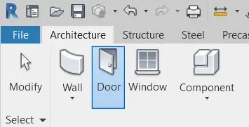
- Select a Category
- Go to the Architectural tab next to File.
- There are different types of categories available to choose from.
- Load Family
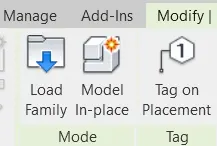
- When you select the category, the modify panel is automatically displayed.
- Click on the Load Family from the modify panel.
- Select the family type
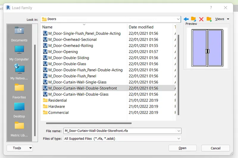
- Once you click on the load family icon, a list of folders containing all family types is displayed.
- You can choose the appropriate family within the same.
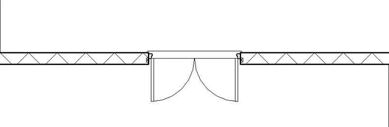
- Place the family into your project
- After selecting a certain family, you can open and place it into your project accordingly.
- Edit elements and change instances
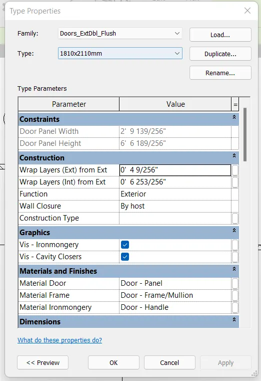
- After placing the family into your project, click on the inserted family.
- And from the left property panel, you can go to the edit type.
- In the edit type, you can change the family element and at the same time, alter different instance parameters like length, width, height, etc.
3) Setting up a Project – Open a project file with an architectural template. Save the file with an appropriate name. Set up the project units to Imperial / Metric based on your convenience of modeling. Complete the project information under the Manage tab. Set up the maximum backups for project files to 3.
STEPWISE PROCEDURE:
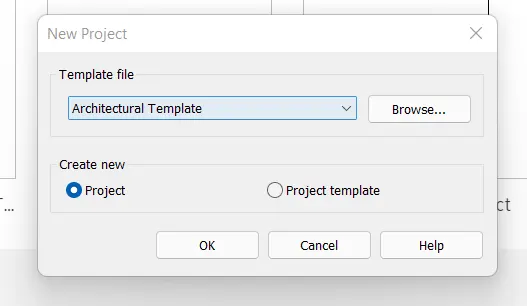
- Select the project template
- Open Revit and wait for it to load completely.
- Once it has loaded 100%, click on the new option on your screen below the project ribbon.
- A dialogue box containing a drop menu with different projects templates will open.
- Select the Architectural template from the list.
- Check the "Project" radio button.
- Hit OK.
- Set up the project units
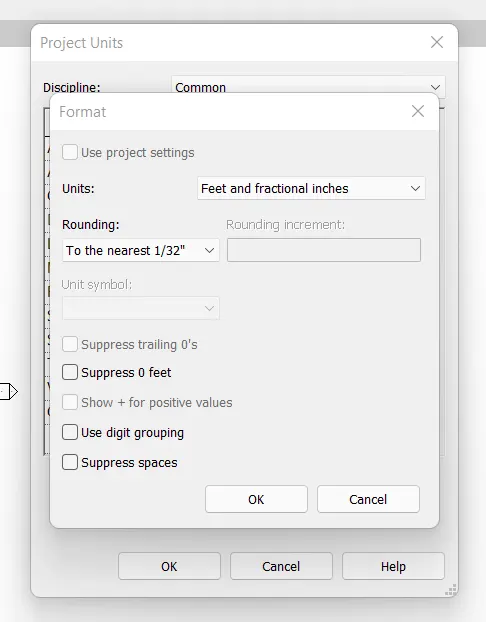
- After opening the new Architectural project, go to the manage tab.
- Click on the project units within the manage tab.
- You can also invoke the project units option by typing "UN" on your keyboard.
- Now, a list of different units for different measurements will appear.
- Go to the length and make sure it precisely corresponds to the current Architectural template.
- Input project information
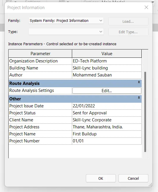
- Again, you need to go to the manage tab and look for the project information option.
- After clicking on it, a tabular form will appear where you need to fill in all your project-related information.
- Basic project details like name, organization, date issued, project type, location, and so on are asked in the tabular form.
- So, you can fill out the relevant information based on the details of your current scenario.
- Save the file with 3 maximum backups
- To save the file, you can either go to file>save or simply press Ctrl+S on your keyboard.
- A dialogue box will appear that will contain the file name, location, and type.
- Give an appropriate name to the file and then select the standard .rvt project file.
- Set up the location by browsing through your local disc and selecting the target folder.
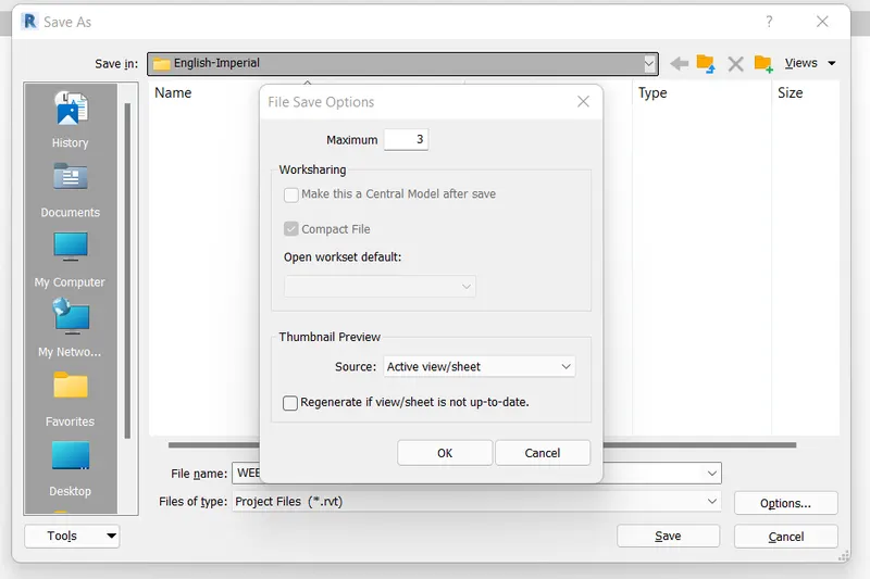
- Now, to set up the maximum backups as 3, click on the "options" menu next to the file name in the current dialogue box.
- It will open up the settings where you can set up the maximum file backups up to 99.
- So, enter 3 next to the maximum backup in settings and then save the project file.
4) Understand the concept of Levels and Grids. Follow the naming and conventions. Create the following Levels: ( Convert to metric equivalents if metric is your units)
Ground Floor @ 0’
First Floor @ 10’
Second Floor @ 20’
Roof @ 30’
Grids Transverse Grids A, B,C,D, E @ 10’ spacing
Longitudinal Grids from 1 to 10 @ 20’ spacing.
Setting up the Levels
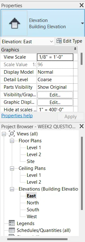
- Levels can only be set up in any of the elevations. You can't fix the levels in the floor plans.
- Terefore, go to the east elevation and understand the initial level set up by the software.
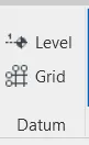
- Then from the Architectural tab>datum, select the levels.
- Level modify panel will open up.
- Select the pick line mode from the same.
- Set up the offset distance as 10'.
- Start picking the levels form groud floor up to the roof at the constant difference of 10'.
- Change the name of each level by double clicking the box.
Open elevation
Click on the level from datum tab
Select the pickline method, set up the offset distance, and start fixing the levels
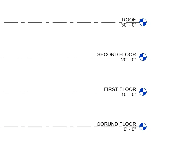
Laying out of grids with the pre-specified spacings
- Click on the grid option available just below the level option.
- Draw the first transverse grid from top to bottom.
- Now, select the pick line option from the modify panel and set up the offset distance of 10'.
- Single click on the lines and draw all the transverse grids.
- Simliarly, follow the exact procedure and lay down the longitudinal grids.
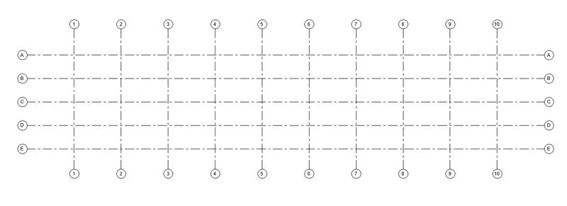
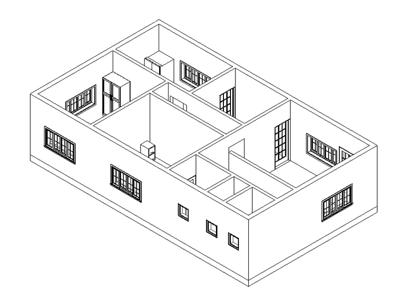
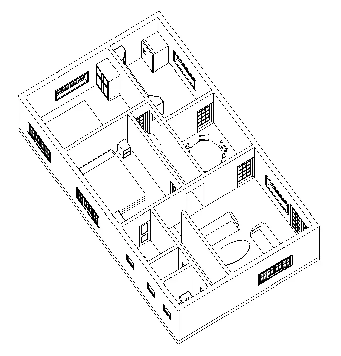
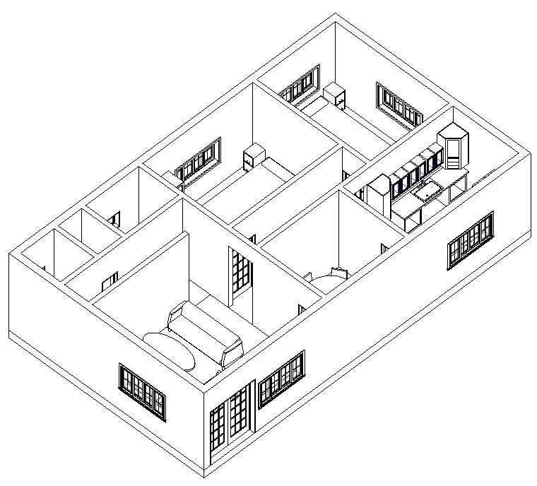
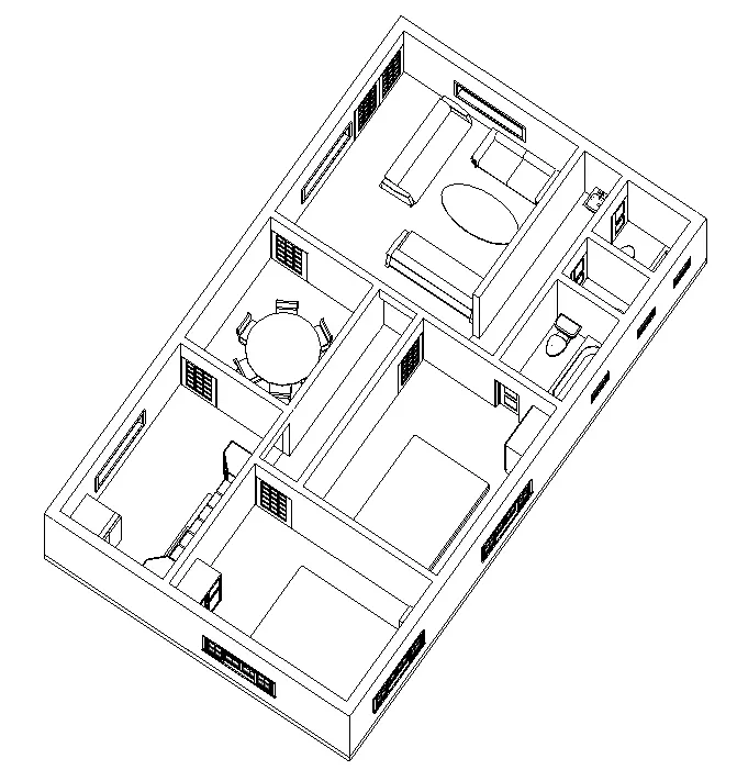
5) 3D modelling of residential unit – From looking at your house / or a place you aspire. Create a conceptual layout of the residential unit. You can measure using a tape or you can access your residential plan to create a similar layout.
STEPWISE PROCEDURE TO PREPARE A RESIDENTIAL FLOOR PLAN IN REVIT
- Open up the Architectural template and set up the imperial units to work in feets and inches.
- Type in "WA->ENTER" and look at the property panel to the left of your screen.
- From the same panel setup the wall specifications.
- Fix the external walls as generic 9".
- Fix the interior walls as generic 6".
- Now select the wall type as per the need and start up with the plan.
- Draw the outer boundary of your residential unit with generic 9".
- Now visualize and dive the spaces into different categories to form rooms.
- Start taking offset in coordination with the room dimensions and to manage the spaces.
- Follow this approach and complete the floor plan by effectively distributing the space. Also, maintain the industry standard room sizes while preparing the floor overlay.
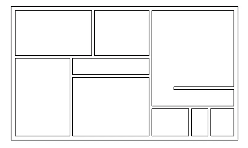
6) In the layout created draft the level of details you are planning to include – Dimensions of room, components you plan to add in the residential unit.
STEPWISE PROCEDURE TO DRAFT THE OPENING DETAILS WITH FURNITURE PLACEMENT IN THE CORRECT POSITIONING.
- First add doors, by selecting the category as doors.
- Then, click on the load family.
- Go through various door files and correlate the needed type as per the directional layout of the floor.
- Select a family and click on open.
- Place and adjust the doors according to the wall positioning.
- Follow the exact procedure to place windows.
- To place the furnishings, click on add component or type in "CM" on your keyboard.
- Select the furniture component from the list.
- Open the file and place it in the desired room.
- Adjust its positioning and size instances as per the space available.
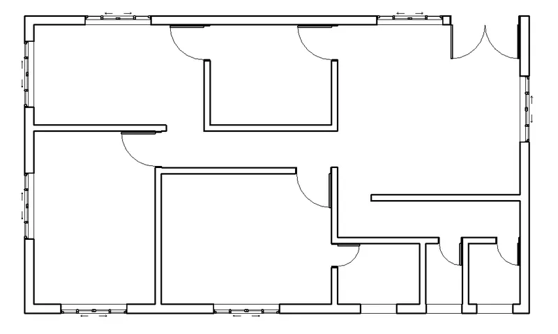
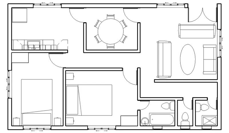
7) Identify the residential model elements such as Door, Windows, Tables, Chair, Couch, Bed, Lamps from the library and insert them to the model . Save the project for further use.
STEPWISE PROCEDURE TO ADD ON THE ROOM TAGS AND OTHER FAMILY ELEMENTS IN THE BUILDING WITH 3D VIEWS:
- First of all, use the room seperator and precisely seperate each room from one another.
- Then, click on the room icon to invoke the tag.
- Start tagging each room.
- Also, do edit type for the room type and set it as name and area.
- Click inside each room and complete the process.
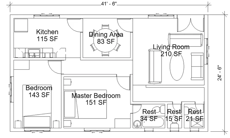
3D VIEWS OF THE RESIDENTIAL UNIT: