Creating Kitchen layout, Hatching of Architectural elements and sectional view of an Industrial Building in AutoCad
Q1
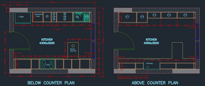
AIM : To draw the kitchen layout as shown in figure
PROCEDURE
STEP 1 :
Type unit or UN in the command box and press enter
Set type of unit as decimal and precision as 0
In Insertion scale set unit as Millimetres
STEP 2 :
Type dimension style manager or D in the command box and press enter
Modify primary units as decimal and precision as 0
STEP 3 :
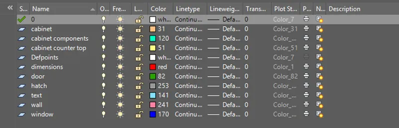
Type layer or LA in the command box and press enter
Create new layers according to drawing given
STEP 4 :
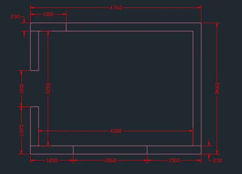
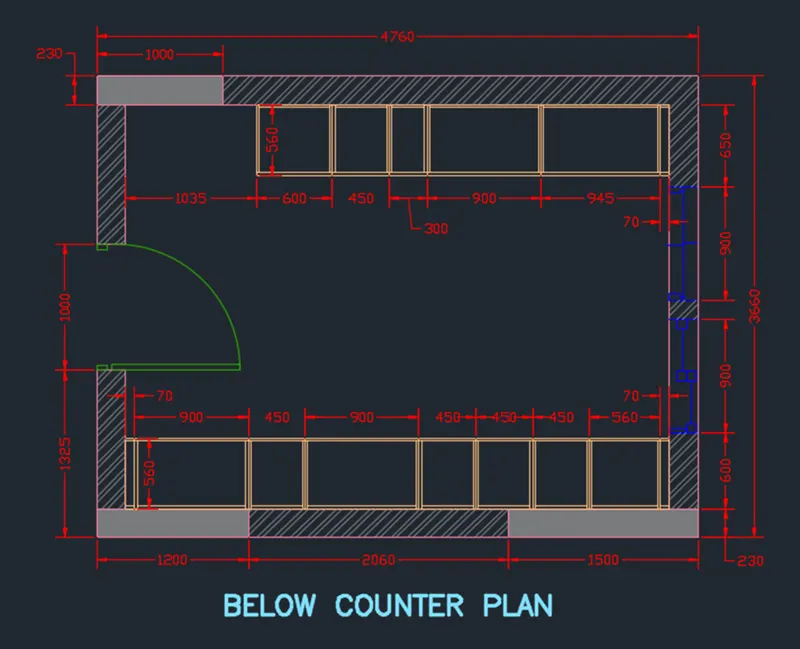
Using line command, offset command, trim command and dimension command draw the layout plan of the kitchen
STEP 5 :
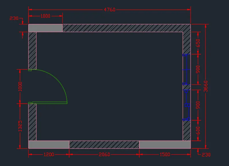
Using line command, arc command, trim command and dimension command draw the door and window of the kitchen
Using hatch command hatch the walls
STEP 6 :
Using line command, offset command, trim command and dimension command draw the cabinet in the Kitchen layout
STEP 7 :
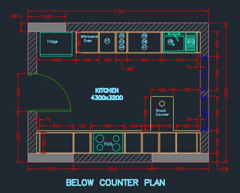
Using line command, offset command, text command and dimension command draw the cabinet counter top and cabinet components in the Kitchen layout
STEP 8 :
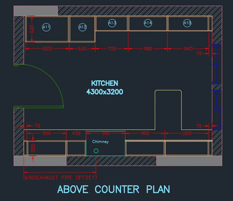
Copy the kitchen layout which was drawn for below counter unit
Using line command, offset command, trim command, text command and dimension command draw the above counter plan in the Kitchen layout
RESULT
The Given figure is drawn using necessary tools in AutoCAD
Q2
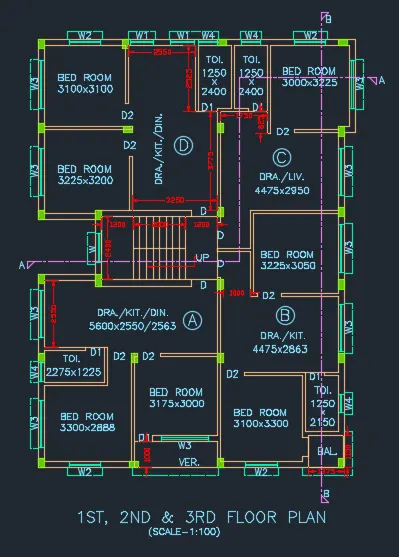
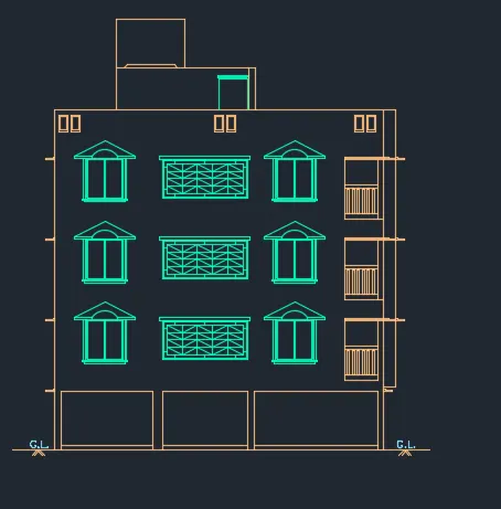
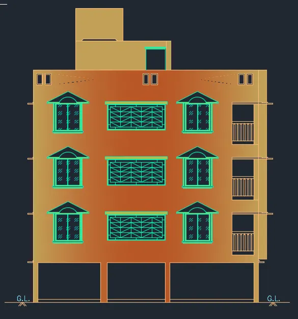
AIM : To create the elevation of the plan created in the Challenges 7 and apply proper hatch in the walls, doors, windows, and other architectural elements. Refer to the dimensions in Plans and sections in Challenges 7.
PROCEDURE
STEP 1 :
Save as the file as challenge 10 and open the new file set the units and dimension style and do all the initial settings as required to the project.
Type unit or UN in the command box and press enter
Set type of unit as decimal and precision as 0
In Insertion scale set unit as Millimetres
Type dimension style manager or D in the command box and press enter
Modify primary units as decimal and precision as 0
Type Xref in the command box and press enter
select challenge 10 autocad file and pres enter so that the file is been imported
STEP 3 :
Type Xline enter and draw the lines as required and draw the elevation of the layout by using line tool, offset tool, trim tool and other necessary AutoCAD tools.
STEP 4 :
Type Hatch or H enter in the command box and press enter and give the hatch to the drawn elevation
RESULT
The Given figure is drawn using necessary tools in AutoCAD
Q3
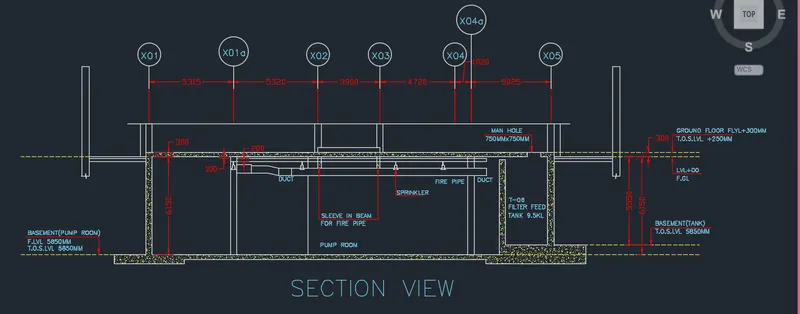
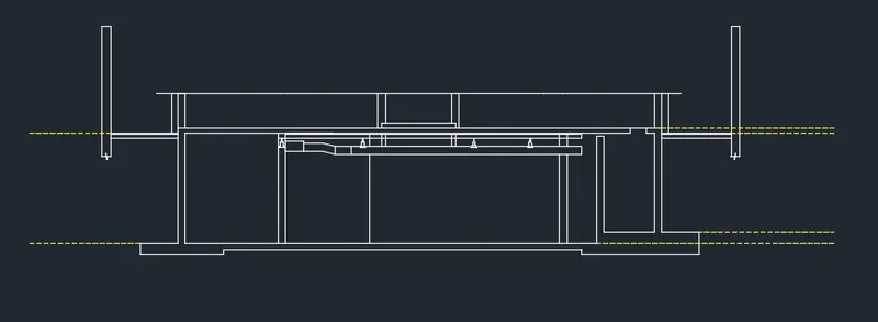
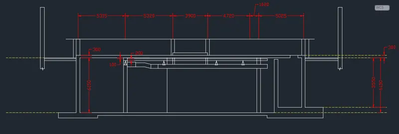
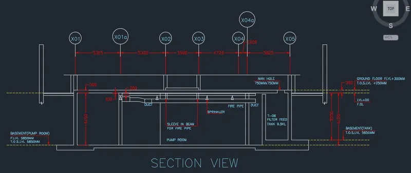
AIM : To create the section view of an industrial building as shown in Figure. Provide appropriate hatches and dimensions wherever required. Also, provide annotations to the drawing.
PROCEDURE
STEP 1 :
Type unit or UN in the command box and press enter
Set type of unit as decimal and precision as 0
In Insertion scale set unit as Millimetres
Type dimension style manager or D in the command box and press enter
Modify primary units as decimal and precision as 0
STEP 2:
By using line command, trim command, offset command and other necessary tools draw the given figure
STEP 3 :
Tpye DIM in the command box abd press enter or select it from the annotate tool bar and give the dimensions wherever required
STEP 4 :
Type Dtext in the command box and press enter and give the text wherever it is necessary.
STEP 5 :
Type Hatch or H enter in the command box and press enter and give the hatch to the drawn section
RESULT
The Given figure is drawn using necessary tools in AutoCAD