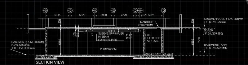
Creating Kitchen layout, Hatching of Architectural elements and sectional view of an Industrial Building in AutoCad
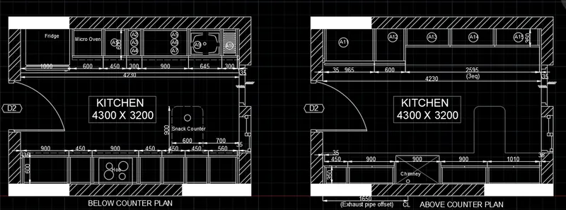
1)LAYOUT OF KITCHEN
AIM: To create the layout of the kitchen and hatch pattern using AutoCAD.
INTRODUCTION: The layout of the kitchen and hatch pattern using AutoCAD is created by Lines. The procedure and result should be written after creating the layout of the kitchen and hatch pattern.
(a)BELOW COUNTER PLAN
STEP 1:
-
Open the AutoCAD software and click start Drawing tab.
-
Enter UNITS in command box.
-
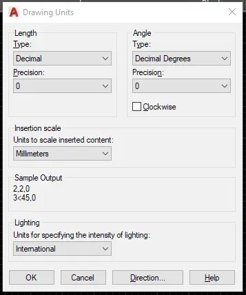
Select DECIMAL in TYPE, 0 in PRECISION and MILLIMETERS in UNITS TO SCALE INSERTED CONTENT. Press OK.
STEP 2:
-
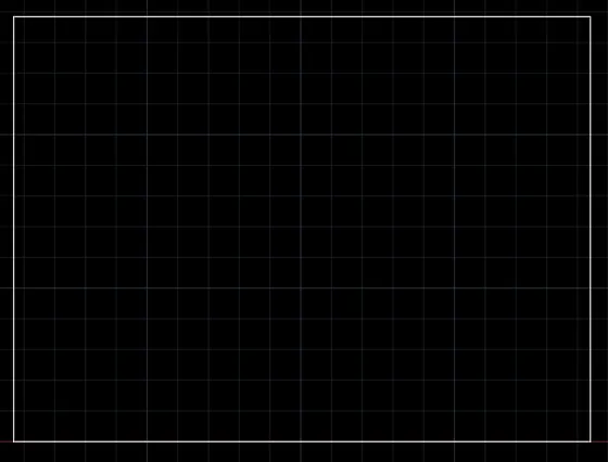
Click Horizontal in the command box
-
Click on the screen
-
Enter 3200 and place the line
-
Enter XL in command box
-
Click Vertical in the command box
-
Click on the screen
-
Enter 4320 and place the line
-
Enter TR in command box
-
Delete the unwanted lines
STEP 3:
-
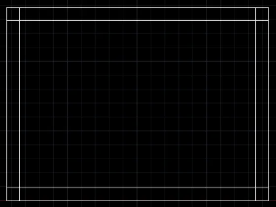
Enter O in command box
-
Enter 230 in the command box
-
Click the lines and create an offset line of 230 mm
-
Repeat the same step for other four lines
STEP 4:
-
Enter L in command box
-
From the midpoint, enter 1000 from both sides
-
Delete the in-between lines
-
Enter L in command box
-
Enter 1000
-
Enter C in command box
-
Click on the point and create a circle
-
Enter TR in command box
-
Delete the unwanted lines
-
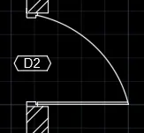
Create a hexagon using line command
-
Enter TEXT in command box
-
Enter 300 as text height
-
Enter D2 inside the hexagon
STEP 5:
-
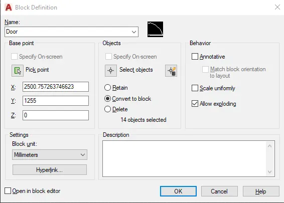
Enter BLOCK in command box
-
Enter DOOR in NAME
-
Pick the point of door
-
Select the entire door
-
Click CONVERT TO BLOCK
-
Clcik OK
STEP 6:
-
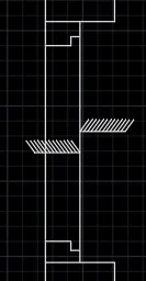
Enter O in command box
-
Enter 115 as offset distance
-
Click the inner wall and place it outwards
-
Enter L in command box
-
Click on the midpoint
-
Enter 100 on both sides
-
Enter L in command box
-
Switch off ORTHOMODE
-
Create the slanting line
-
Enter COPY in command box
-
Copy the slanting line and click ARRAY
-
Enter 20 as number of lines
-
Click FIT
-
Press ENTER
-
Enter MI in command box
-
Select the slanting lines
-
Place it in opposite side
-
Press ENTER
STEP 7:
-
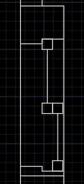
Enter L in command box
-
Enter 200 as first point
-
Enter 115 as next point
-
Enter 20 as next point
-
Connect it to the opposite side
-
Enter REC in command box
-
Enter 50 as length and breadth
-
Copy the square and place it in the appropriate position
STEP 8:
-
Enter H in command box
-
Click SOLID
-
Place it in the appropriate place
-
Click STEEL
-
Place it in the appropriate place
-
Enter 20 as scale
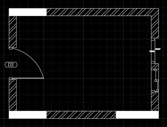
STEP 9:
-
Enter B in command box
-
Enter COUNTER PLAN as NAME
-
Pick the point of counter plan
-
Select the counter plan as a whole
-
Click CONVERT TO BLOCK
-
Press OK
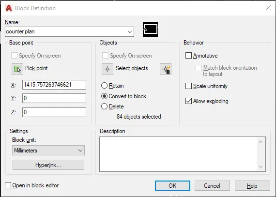
STEP 10:
-
Enter L in command box
-
Trace the inner wall and enter 600 as first point
-
Enter 35 as next point
-
Press ENTER
-
Enter 900 as offset distance
-
Enter O in command box
-
Enter 450 as offset distance
-
Enter O in command box
-
Enter 900 as offset distance
-
Enter O in command box
-
Enter 450 as offset distance
-
Enter O in command box
-
Enter 560 as offset distance
-
Press ENTER
-
Enter O in command box
-
Enter 30 as offset distance
-
Place it in the required place
-
Enter L in command box
-
Enter 100 as first point
-
Enter 500 as next point
-
Enter 600 as next point
-
Close the line
-
Press ENTER
-
Click the point in the screen
-
Enter 30 as radius
-
Enter C in command box
-
Click the point in the screen
-
Enter 70 as radius
-
Copy the two circles
-
Place it at the opposite side

STEP 11:
-
Enter L in command box
-
Trace the line and enter 700 as first point
-
Enter 900 as next point
-
Enter 600 as next point
-
Close the line
-
Enter C in command box
-
Enter 50 as radius
-
Click ENTER
-
Enter F in command box
-
Enter 50 as fillet radius
-
Make the corners as curve
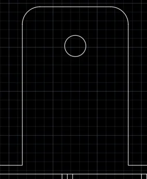
STEP 12:
-
Enter L in command box
-
Enter 600 as first point
-
Enter 35 as next point
-
Press ENTER
-
Enter O in command box
-
Enter 300 as offset distance
-
Enter O in command box
-
Enter 645 as offset distance
-
Enter O in command box
-
Enter 900 as offset distance
-
Enter O in command box
-
Enter 300 as offset distance
-
Enter O in command box
-
Enter 450 as offset distance
-
Enter O in command box
-
Enter 600 as offset distance
-
Enter O in command box
-
Enter 30 as offset distance
-
Place it in the required place
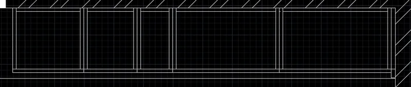
STEP 13:
-
Enter L in command box
-
Enter 100 as first point
-
Enter 700 as next point
-
Enter 800 as next point
-
Enter 700 as next point
-
Press ENTER
-
Enter O in command box
-
Enter 30 as offset distance
-
Enter O in command box
-
Enter 50 as offset distance
-
Close the offset lines
-
Press ENTER
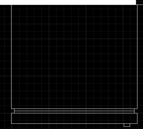
STEP 14:
-
Enter L in command box
-
Enter 100 as first point
-
Enter 200 as next point
-
Enter 30 as next point
-
Close the rectangle
-
Press ENTER
-
Enter ARC in command box
-
Make the two edges as curves
-
Delete the unwanted lines
-
Enter COPY in command box
-
Select the object
-
Click ARRAY in command box
-
Enter 10 as number of items
-
Click FIT and place it in the required place
-
Switch off ORTHOMODE
-
Create four inclined lines with space of 200mm
-
Enter F in command box
-
Enter 50 as fillet radius
-
Enter L in command box
-
Create four straight lines with space of 200mm
-
Enter C in command box
-
Enter 30 as radius
-
Press ENTER
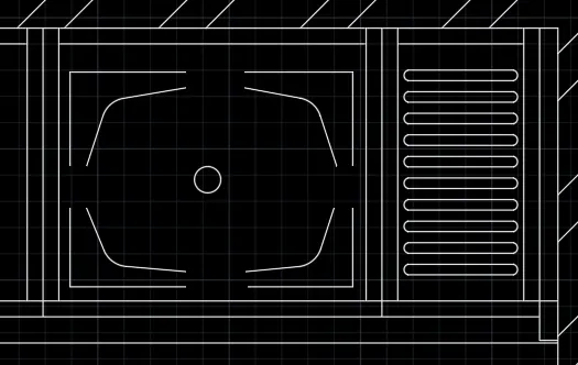
STEP 15:
-
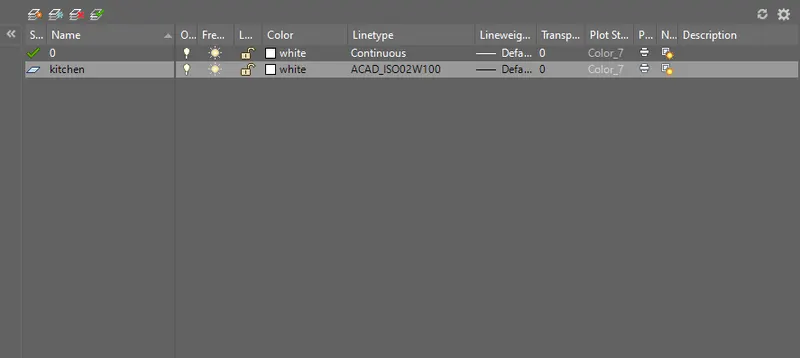
Click LAYER PROPERTIES
-
Click NEW LAYER
-
Enter KITCHEN in NAME
-
Select ACAD_ISO02W100 in LINETYPE
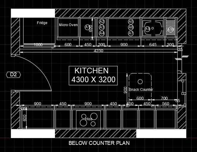
STEP 16:
-
Select ISO DASH with space of 10
-
Enter TEXT in command box
-
Enter 300 as text height
-
Enter the text in the required place
-
Enter DIM in command box
-
Enter 300 as ARROW SIZE
-
Enter 300 as TEXT SIZE
-
Create the dimension lines
(b)ABOVE COUNTER PLAN
STEP 1:
-
Enter I in command box
-
Select COUNTER PLAN in NAME
-
Press OK
-
Place the block on the required place
-
Enter L in command box
-
Enter 350 as first point
-
Enter O in command box
-
Enter 450 as offset distance
-
Enter O in command box
-
Enter 900 as offset distance
-
Enter O in command box
-
Enter 1010 as offset distance
-
Place the offset distance on the appropriate place
-
Enter O in command box
-
Enter 30 as offset distance
-
Place it in the appropriate position
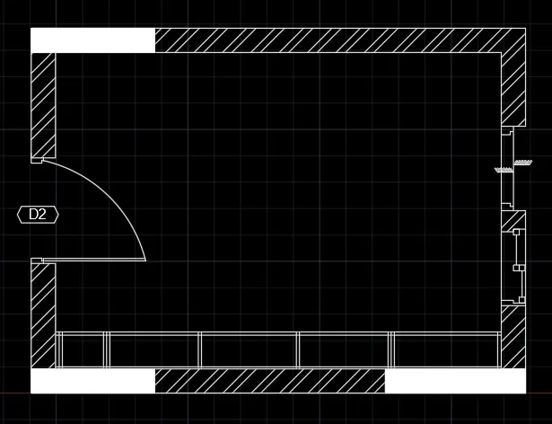
STEP 2:
-
Enter L in command box
-
Enter 50 as first point
-
Enter 600 as next point
-
Enter 800 as next point
-
Close the line
-
Press ENTER
-
Enter DIM in command box
-
Click the inner wall and enter 1650
-
Enter 300 as TEXT SIZE
-
Enter 300 as ARROW SIZE
-
Enter C in command box
-
Enter 30 as radius
-
Place it in the required place
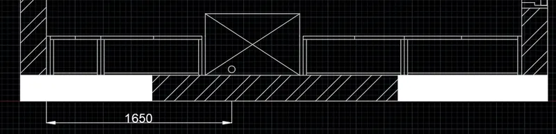
STEP 3:
-
Enter L in command box
-
Enter 35 as first point
-
Enter O in command box
-
Divide 2595 and place the offset line
-
Enter 600 as offset distance
-
Enter O in command box
-
Enter 965 as offset distance
-
Enter O in command box
-
Enter 30 as offset distance
-
Enter C in command box
-
Enter 80 as radius
-
Enter TEXT in command box
-
Enter 70 as TEXT SIZE
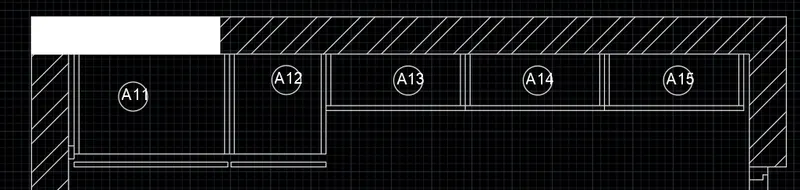
STEP 4:
-
Click LAYER PROPERTIES
-
Select ISO DASH with space of 10
-
Enter TEXT in command box
-
Enter 300 as text height
-
Enter the text in the required place
-
Enter DIM in command box
-
Enter 300 as ARROW SIZE
-
Enter 300 as TEXT SIZE
-
Create the dimension lines
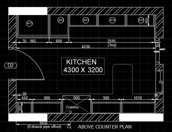
RESULT:
The Layout of the kitchen and hatch pattern is created by lines using AutoCAD. The step-by-step procedure for creating layout of the kitchen is also explained. The Dimension is also entered in the diagram.
2)ELEVATION OF PLAN
AIM: To create the elevation of plan and hatch pattern in walls, doors and windows using AutoCAD.
INTRODUCTION: The elevation of plan and hatch pattern in walls, doors and windows using AutoCAD is created by Lines. The procedure and result should be written after creating the elevation of plan and hatch pattern in walls, doors and windows.
STEP 1:
-
Open the AutoCAD software and click start Drawing tab.
-
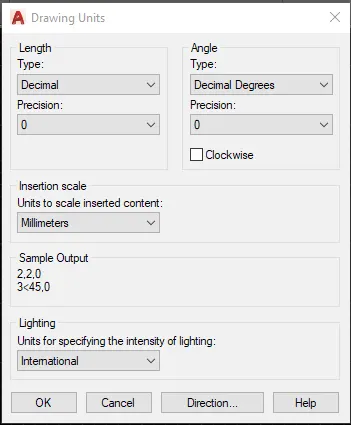
Enter UNITS in command box.
-
Select DECIMAL in TYPE, 0 in PRECISION and MILLIMETERS in UNITS TO SCALE INSERTED CONTENT. Press OK.
STEP 2:
-
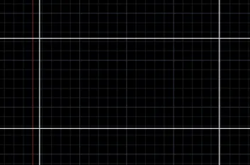
Click HORIZONTAL LINE in command box
-
Click on the screen
-
Enter XL in command box
-
Click HORIZONTAL LINE in command box
-
Enter 12000
-
Enter XL in command box
-
Click VERTICAL LINE in command box
-
Click on the screen
-
Enter XL in command box
-
Click VERTICAL LINE in command box
-
Enter 25000
-
Press ENTER
STEP 3:
-
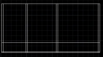
Enter 200 as offset distance
-
Enter O in command box
-
Enter 2450 as offset distance
-
Enter O in command box
-
Enter 250 as offset distance
-
Enter O in command box
-
Enter 4000 as offset distance
-
Enter O in command box
-
Enter 5000 as offset distance
-
Enter O in command box
-
Enter 250 as offset distance
-
Place the lines in the required position
STEP 4:
-
Enter TR in command box
-
Delete the offset lines
-
Delete the unwanted lines of pillars
-
Press ENTER
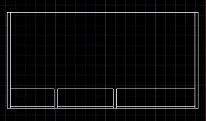
STEP 5:
-
Enter L in command box
-
Trace the inner wall from the bottom
-
Enter 500 as first point
-
Enter 1000 as next point
-
Close the line
-
Press ENTER
-
Copy the rectangle and place it in the distance of 500mm
-
Enter O in command box
-
Enter 800 as offset distance
-
Enter L in command box
-
Trace the line and enter 600 as first point
-
Enter CO in command box
-
Copy the rectangle and place it in the distance of 1000mm
-
Enter 600 as offset distance
-
Enter O in command box
-
Enter 2000 as offset distance
-
Enter L in command box
-
Enter 600 as first point
-
Place it at the distance of 1000mm
-
Enter CO in command box
-
Place the three rectangles at the distance of 1000mm
-
Press ENTER
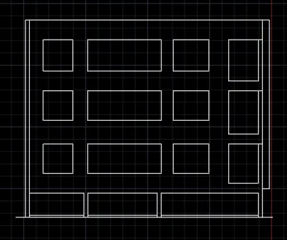
STEP 6:
-
Enter L in command box
-
Enter 400 as first point
-
Enter O in command box
-
Enter 50 as offset distance
-
Enter L in command box
-
Enter 20 as first point
-
Enter O in command box
-
Enter 30 as offset distance
-
Enter CO in command box
-
Click ARRAY in command box
-
Enter 6 as number of items
-
Click FIT
-
Press ENTER
-
Enter O in command box
-
Enter 20 as offset distance
-
Repeat it another time
-
Press ENTER
-
Enter CO in command box
-
Select the object
-
Click ARRAY
-
Enter 3 as number of items
-
Place it in the appropriate place
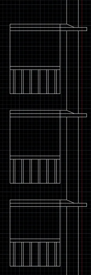
STEP 7:
-
Enter 50 as offset distance
-
Repeat this step for four times
-
Enter O in command box
-
Enter 70 as offset distance
-
Repeat this step for two times
-
Enter O in command box
-
Enter 30 as offset distance
-
Repeat this step for two times
-
Enter O in command box
-
Enter 50 as offset distance
-
Repeat this step for four times
-
Enter TR in command box
-
Delete all the unwanted lines
-
Enter C in command box
-
Place the centre at the centre of the window
-
Enter TR in command box
-
Delete the other half of the circle
-
Enter O in command box
-
Enter 30 as offset distance
-
Switch off ORTHOMODE
-
Create two slanting lines
-
Enter O in command box
-
Enter 30 as offset distance
-
Press ENTER
-
Enter H in command box
-
Click CORK GLASS
-
Place it in the required place
-
Enter 20 as scale
-
Press ENTER
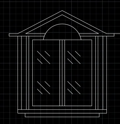
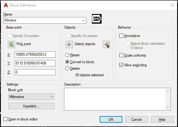
STEP 8:
-
Enter B in command box
-
Enter WINDOW in NAME
-
Pick the point of window
-
Select the window
-
Click CONVERT TO BLOCK
-
Press OK
STEP 9:
-
Enter CO in command box
-
Copy the window
-
Place it at the distance of 2000
-
Press ENTER

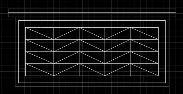
STEP 10:
-
Enter 100 as offset distance
-
Place it at four sides
-
Enter O in command box
-
Enter 500 as offset distance
-
Place it at four sides
-
Enter L in command box
-
Click on the midpoint and close the line
-
Enter O in command box
-
Enter 1000 as offset distance
-
Place it at either side
-
Place the offset lines in the required place
-
Place the four offset lines vertically
-
Switch off ORTHOMODE
-
Place the line in the appropriate positions
-
Enter CO in command box
-
Copy the line and place it in the below portions
-
Press ENTER
-
Enter TR in command box
-
Delete the unwanted lines
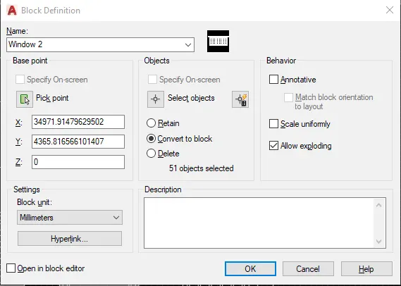
STEP 11:
-
Enter B in command box
-
Enter WINDOW2 in NAME
-
Pick point of the window
-
Select the window
-
Click CONVERT TO BLOCK
-
Press OK
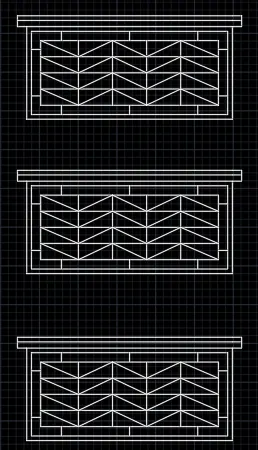
STEP 12:
-
Enter CO in command box
-
Copy the window
-
Place the window at the distance of 2000
-
Press ENTER
STEP 13:
-
Enter CO in command box
-
Copy the three windows
-
Place it at the distance of 23000
-
Press ENTER
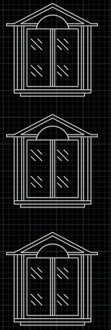
STEP 14:
-
Enter L in command box
-
Enter 4000 as first point
-
Enter 8000 as next point
-
Close the line
-
Enter L in command box
-
Enter 2000 as first point
-
Enter 5000 as next point
-
Close the line
-
Enter O in command box
-
Enter 500 as offset distance
-
Enter 200 as offset distance
-
Enter O in command box
-
Enter 2000 as offset distance
-
Enter O in command box
-
Enter 200 as offset distance
-
Enter O in command box
-
Enter 500 as offset distance
-
Press ENTER
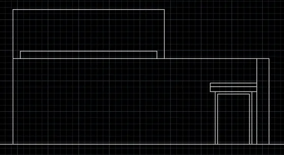
STEP 15:
-
Enter REC in command box
-
Enter 600 as length
-
Enter 500 as breadth
-
Enter O in command box
-
Enter 50 as offset distance
-
Enter CO in command box
-
Copy the rectangle
-
Place it at the distance of 200mm
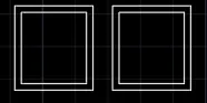
STEP 16:
-
Enter CO in command box
-
Copy the two rectangles
-
Place it at the appropriate position

STEP 17:
-
Enter L in command box
-
Switch off ORTHOMODE
-
Click on the outer wall
-
Enter 200 as next point
-
Switch on ORTHOMODE
-
Enter 50 as next point
-
Close the line
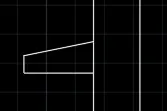
STEP 18:
-
Enter CO in command box
-
Copy the object
-
Click ARRAY
-
Enter 4 as number of items
-
Click FIT
-
Press ENTER

STEP 19:
-
Enter L in command box
-
Switch off ORTHOMODE
-
Enter 500 as first point
-
Entre 200 as offset distance
-
Repeat it for one time
-
Enter MI in command box
-
Select the line and place it in the other side
-
Enter O in command box
-
Entre 200 as offset distance
-
Repeat it for one time
-
Press ENTER
STEP 20:
-
Enter TEXT in command box
-
Enter 500 as TEXT HEIGHT
-
Enter the text in the required place
-
Press ENTER
RESULT:
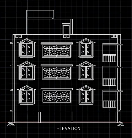
The Elevation of plan and hatch pattern in walls, doors and windows is created by lines using AutoCAD. The step-by-step procedure for creating elevation of plan is also explained. The Dimension is also entered in the diagram.
3)SECTION VIEW OF AN INDUSTRIAL BUILDING
AIM: To create the section view of an ndustrial building using AutoCAD.
INTRODUCTION: The Section view of an industrial building using AutoCAD is created by Lines. The procedure and result should be written after creating the section view of an industrial building.
STEP 1:
-
Open the AutoCAD software and click start Drawing tab.
-
Enter UNITS in command box.
-
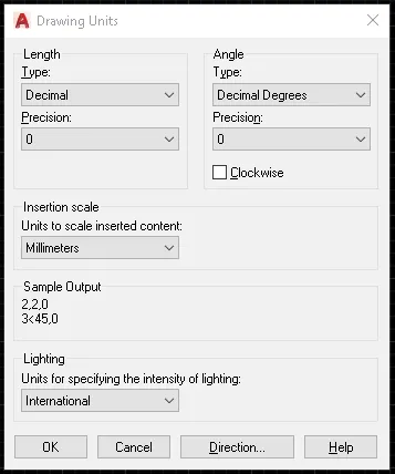
Select DECIMAL in TYPE, 0 in PRECISION and MILLIMETERS in UNITS TO SCALE INSERTED CONTENT. Press OK.
STEP 2:
-
Click HORIZONTAL LINE in command box
-
Click on the screen
-
Enter XL in command box
-
Click HORIZONTAL LINE in command box
-
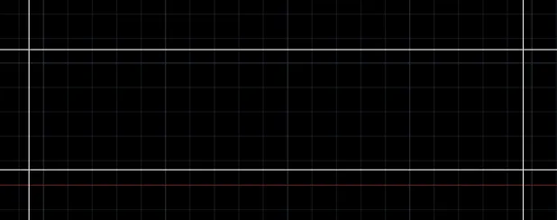
Enter 25300
-
Enter XL in command box
-
Click VERTICAL LINE in command box
-
Click on the screen
-
Enter XL in command box
-
Click VERTICAL LINE in command box
-
Enter 6150
-
Press ENTER
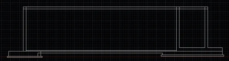
STEP 3:
-
Enter 300 as offset distance
-
Enter O in command box
-
Enter 100 as offset distance
-
Enter O in command box
-
Enter 200 as offset distance
-
Enter O in command box
-
Enter 500 as offset distance
-
Enter O in command box
-
Enter 200 as offset distance
-
Enter O in command box
-
Enter 350 as offset distance vertically
-
Enter O in command box
-
Enter 22000 as offset distance
-
Enter O in command box
-
Enter 350 as offset distance
-
Enter O in command box
-
Enter 3000 as offset distance
-
Press ENTER
-
Enter TR in command box
-
Delete the unwanted lines
STEP 4:
-
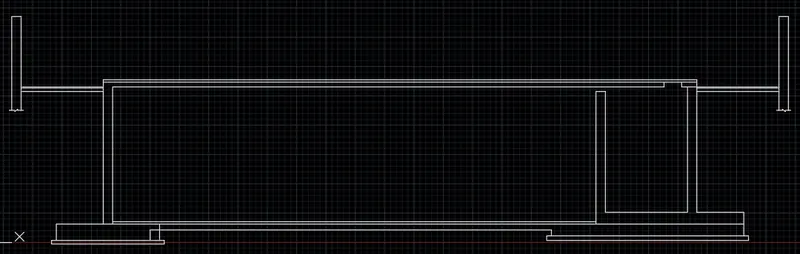
Enter 100 as offset distance
-
Enter L in command box
-
Enter 3000 as first point
-
Enter O in command box
-
Enter 100 as offset distance
-
Enter L in command box
-
Enter 3000 as first point
-
Enter 400 as next point
-
Enter 4000 as next point
-
Enter 400 as next point
-
Connect it to the point
-
Enter CO in command box
-
Copy the object
-
Place it at the right side
-
Enter TR in command box
-
Delete the unwanted lines
STEP 5:
-
Enter 400 as offset distance
-
Enter O in command box
-
Enter 450 as offset distance
-
Enter L in command box
-
Click on the midpoint
-
Enter O in command box
-
Enter 800 as offset distance
-
Enter O in command box
-
Enter 400 as offset distance
-
Enter O in command box
-
Enter 300 as offset distance
-
Place it horizontally

STEP 6:
-
Enter 30 as offset distance
-
Enter O in command box
-
Enter 70 as offset distance
-
Enter O in command box
-
Enter 200 as offset distance
-
Create slanting lines
-
Switch on OTHOMODE
-
Enter L in command box
-
Enter 200 as first point
-
Enter 50 as next point
-
Enter 200 as next point
-
Close the line
-
Switch off OTHOMODE
-
Create the trapezium
-
Enter CO in command box
-
Copy the object
-
Click ARRAY
-
Enter 5 as number of items
-
Click FIT
-
Press ENTER

STEP 7:
-
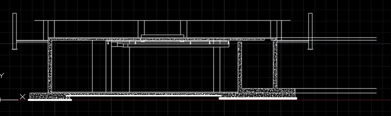
Enter H in command box
-
Click SOLID in command box
-
Select the object
-
Enter 10 as scale
-
Enter H in command box
-
Click CONCRETE in command box
-
Select the object
-
Enter 10 as scale
STEP 8:
-
Click on Single Line Text Annotative
-
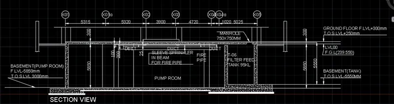
Enter 400 as TEXT SIZE
-
Enter the text in the required place
-
Enter LEADER in command box
-
Click on the appropriate place and enter the text
-
Enter 400 as TEXT SIZE
-
Enter C in command box
-
Enter 500 as radius
-
Place the circle above the dimension line
-
Enter CO in command box
-
Copy the circle
-
Click ARRAY
-
Enter 7 as number of items
-
Click FIT
-
Press ENTER
STEP 9:
-
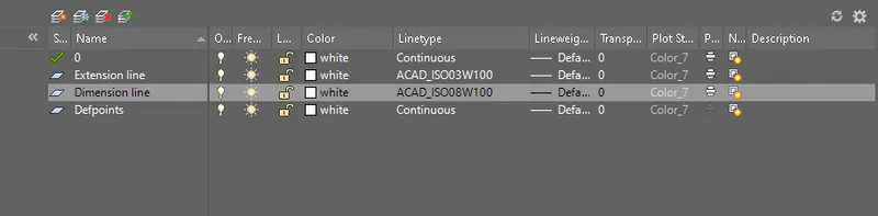
Click LAYER PROPERTIES
-
Enter EXTENSION LINE and DIMENSION LINE
-
Enter ACAD_ISO03W100 and ACAD_ISO08W100
STEP 10:
-
Click the extension line and apply ISO DASH SPACE
-
Enter 10 as scale
-
Click the dimension line and apply ISO DASH LONG SHORT SPACE
-
Enter 10 as scale
RESULT:
The section view of an industrial building created by lines using AutoCAD. The step-by-step procedure for creating elevation of plan is also explained. The Dimension is also entered in the diagram.