Creating Kitchen layout, Hatching of Architectural elements and sectional view of an Industrial Building in AutoCad
Name: Allan Bryan Jayson Cruz
Course: Master’s Certification Program in High-Rise Building Design & Analysis
Date: November 19, 2021
Challenge 9_Creating Kitchen layout, Hatching of Architectural elements and sectional view of an Industrial Building in AutoCAD
********************************************************
1. Aim & Introduction
***************
Aim
This challenge aims to let the student experience a hands on application of the hatching command in the AutoCAD software while providing an inner collaboration with architectural sketches. It allows the student to understand the importance of the hatching tool in such sketches. It also aims to practice the student in sketching residential or architectural works while utilizing the tools provided by the AutoCAD software.
Introduction
The AutoCAD software provides different tools. The tools used in this challenge is as described below:
Line - creates line object.
Polyline - creates connected line object.
Rectangle - creates rectangle object.
Circle - create circle object.
Trim - Cut unwanted lines or shapes with the provided cutting edges.
Extend - Extend lines to opposite corners.
Move - Move objects to particular locations.
Copy - Copy objects to particular locations.
Rotate - Rotate selected objects to a particular angle with respect to base point.
Array - Copy an object in a set path linearly or polarly.
Join – Joins separated line objects into one object. Line to polyline.
Dimlinear (DLI) - Provides vertical or horizontal linear/straight dimensions.
Dimaligned (DAL) - Provides aligned dimensions.
Dimangular (DAN) – Provides angular dimensions.
Quickdimension (QDIM) – Provides quick dimension of a geometry.
Leader - Creates an arrowhead line.
Layers - Provide identification of line or object groups by their properties.
Units - Open "Drawing Units" window to specify the drawings units.
Dimstyle - Open "Dimension Style Manager" window to modify the dimension properties.
Hatch - Provides hatching pattern in a given object or internal point.
Layer - Open the layer tab which manages the line properties in a drawing.
********************************************************
2. Sketch and Procedure
***************
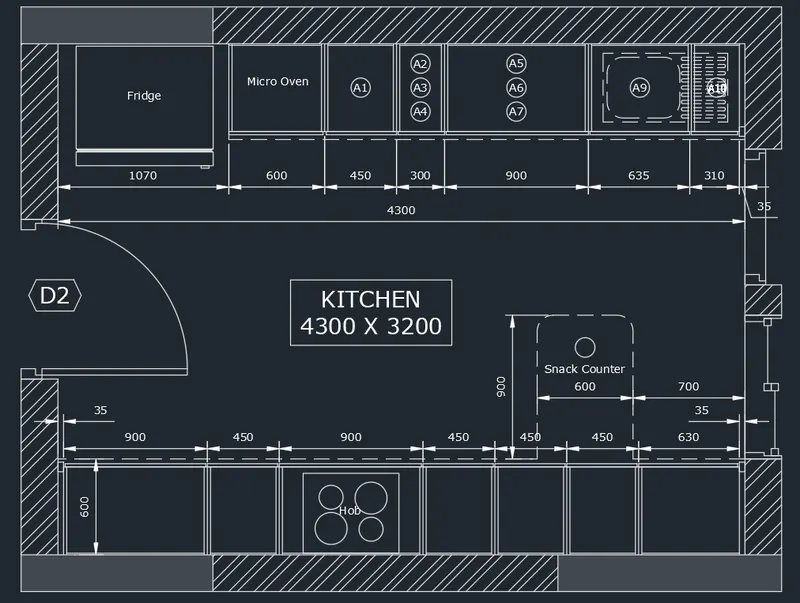
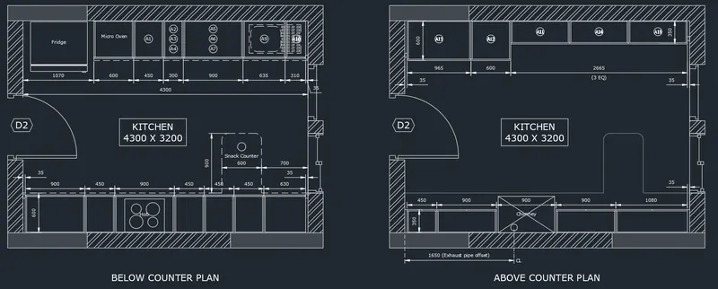
A. Create the layouts of the Kitchen and provide hatches pattern as shown. Also, use blocks wherever required. Provide appropriate dimensions in the plan. Assume the size of doors, appliances, and others as per the standards.
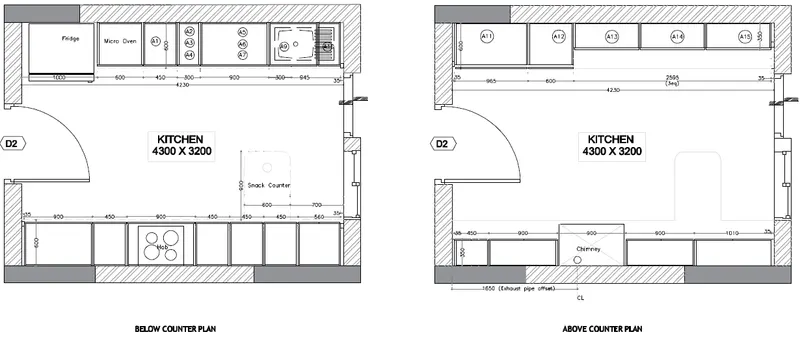
PROCEDURE:
--> Proceed with the wall, doors and windows. This image is present on both plans.
- Create the inside boundary using rectangle command. Offset the by 230mm outside to create the wall thickness.
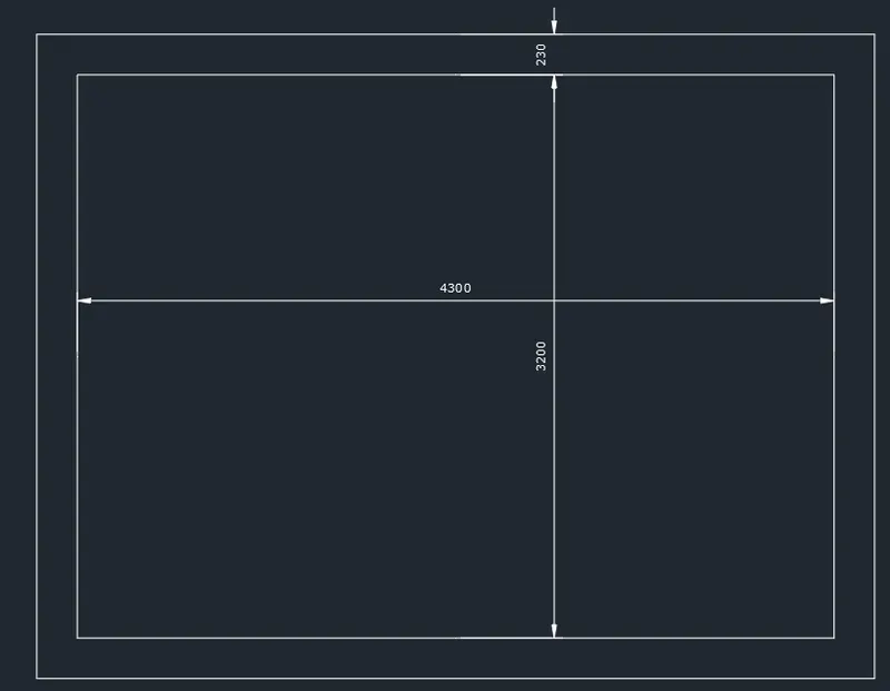
- Explode the rectangles. Offset to make the openning boundary and trim.
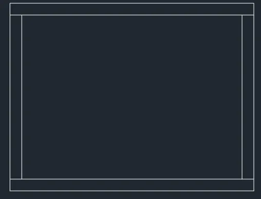
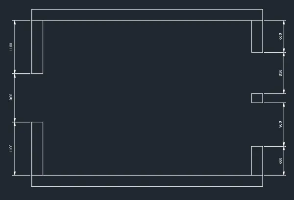
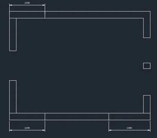
- Create the hatching boundaries.
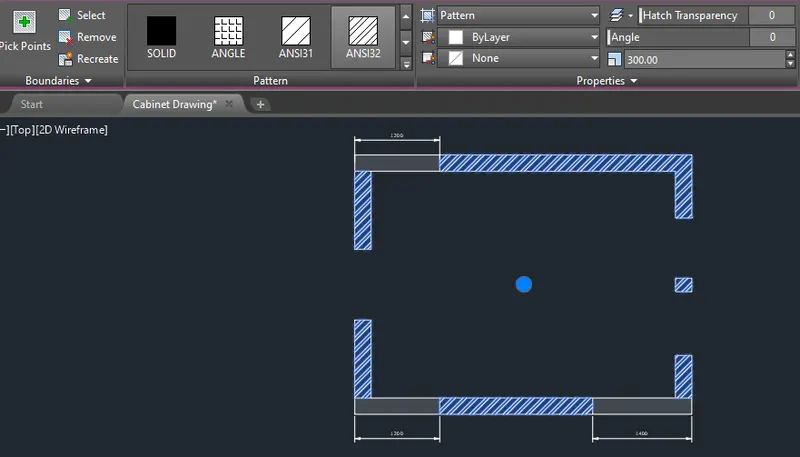
- Hatch the wall using "Pick internal points" and edit using the hatch tab on top of the interface or the properties tab.
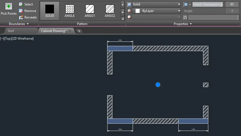
- Create the door. Use polylines, rectangles and circles. Utilize mirror tool as well.
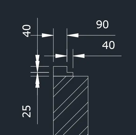
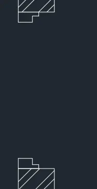
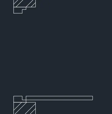
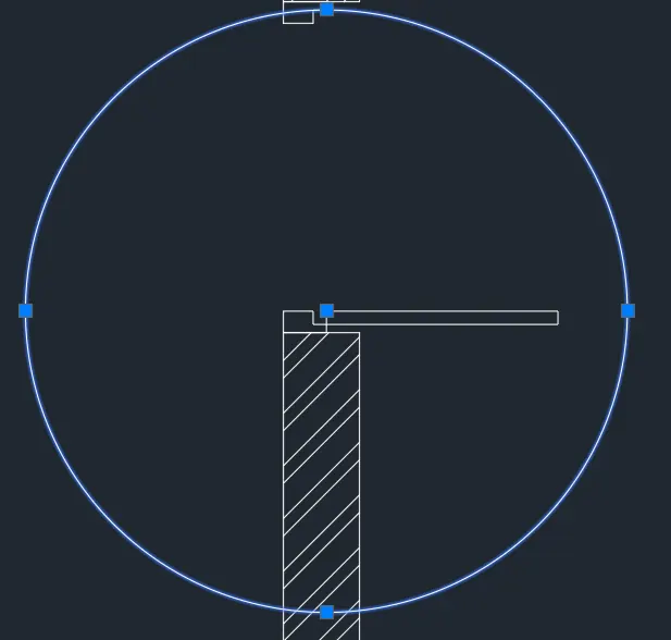
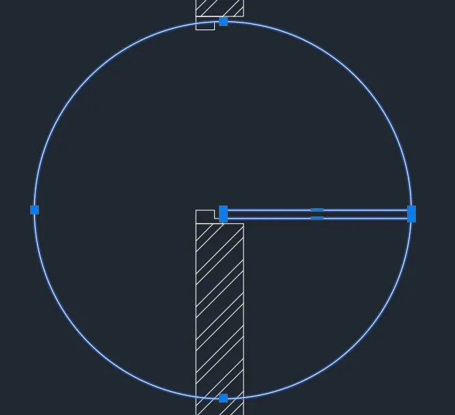
- Trim and complete.
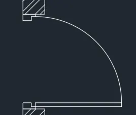
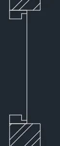
- Proceed with the window sketch. Use the same tools used in creating the door.
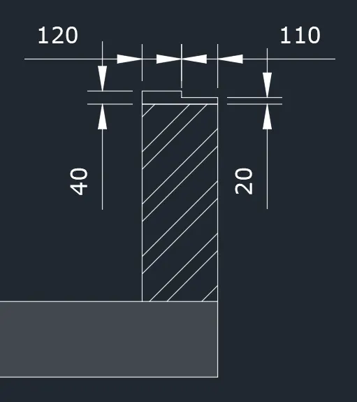
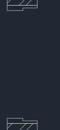
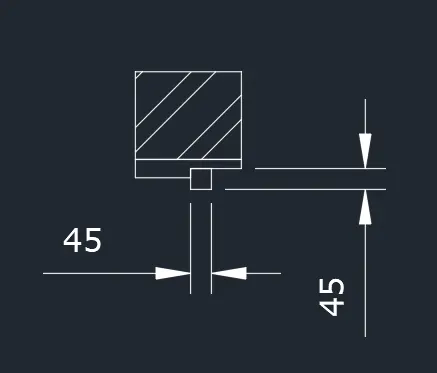
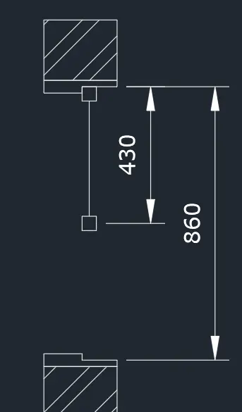
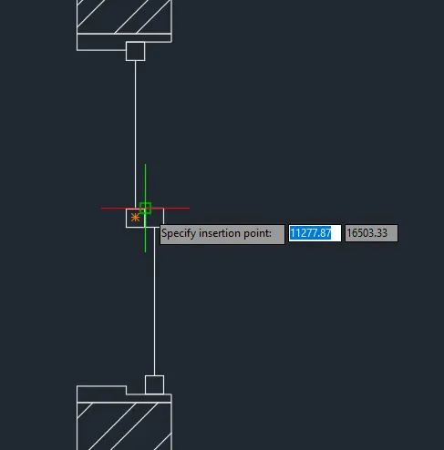
- Copy the door boundary for the 2nd window.
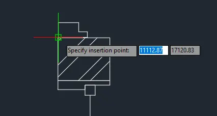
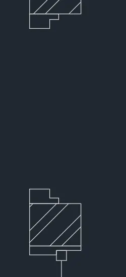
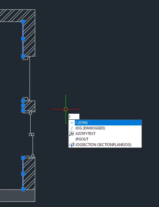
- Join the lines to close the window.
- Duplicate the plan for above and below counter.
--> Preceed with below the counter plan.
- Create lines.
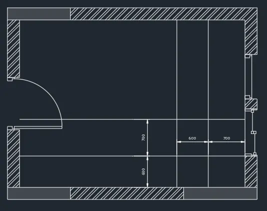
- Trim lines.
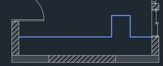
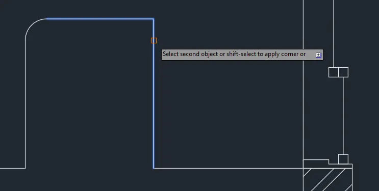
- Fillet corners with radius 100.
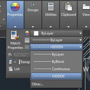
- Change linetype to Hidden. Change line scale in properties tab to show the lines.
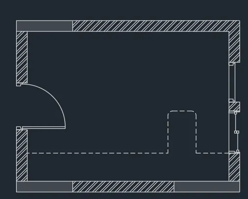
- Create the lines for the intersection. Use line and copy tool.
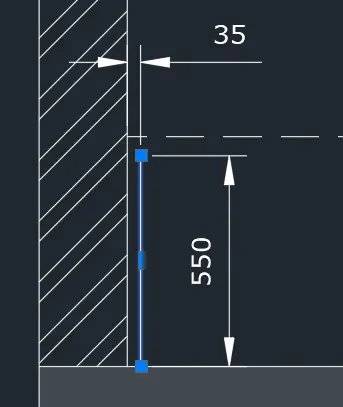
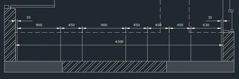
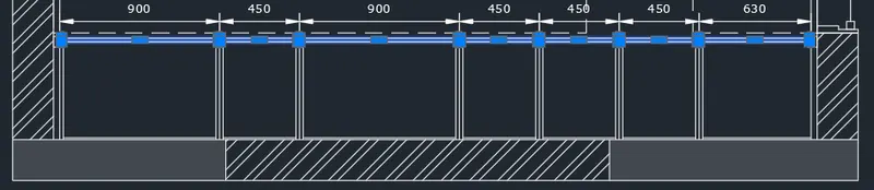
- To create dimensions, use dimlinear command and dimcontinue for easy progress.
- Adjustments are provided to accomodate the 4300 inner dimension.
- Offset lines to create depth. Use trim to cut unnecessary lines.
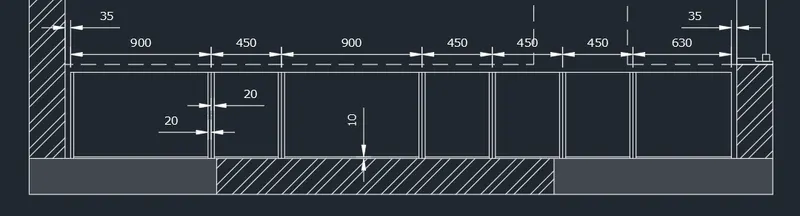
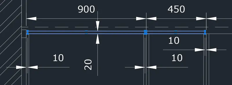
- Add the rectangle object at the corners and sketch the door using rectangle and move tool. Utilize the sketch tool to for easy progress. Use 10mm spacing for the doors and 20mm thickness.
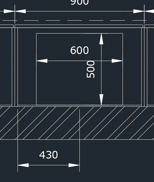
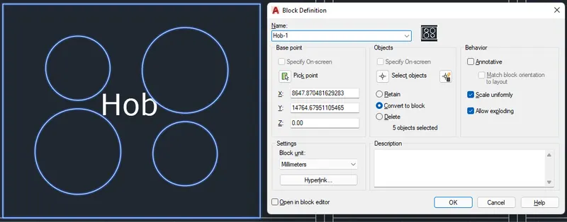
- Create the Hob sketch. Use rectangle with 600x500 dimension. Circles with dimater of 200 and 150.
- Turn on Geometric Center in the Osnap settings to check the center of the rectangle.
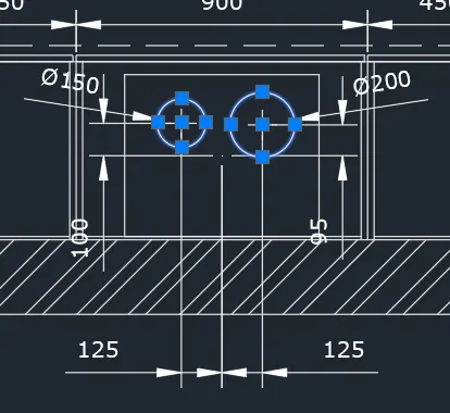
- Use mirror with center of the rectangle as mirror plane to dumplicate the objects.
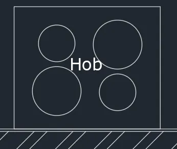
- Then mirror again to invert the objects.
- Use dtext to add the text object.
- Proceed with the top part. Create boundary lines using line tools.
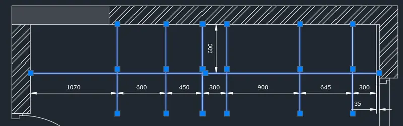
- Trim the lines and add line objects to enclose the boundaries.
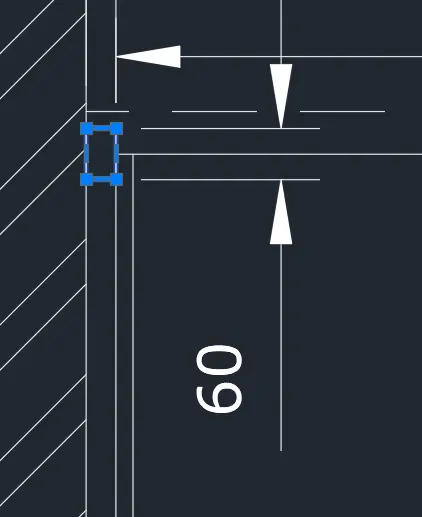
- Vertical line thickness is 20mm both sides. The top line is 10mm and 50mm for the bottom line.
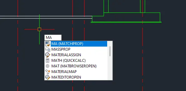
- Change the outer bottom line to hidden line. Use match properties (ma) command for easy progress.
- Trim unnecessry lines to finish.
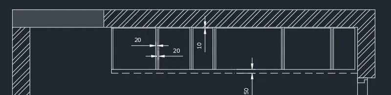
- Create the rectangle on the lower right side.
- Create the doors with 20mm thickness and 10mm spacing same as the first one.
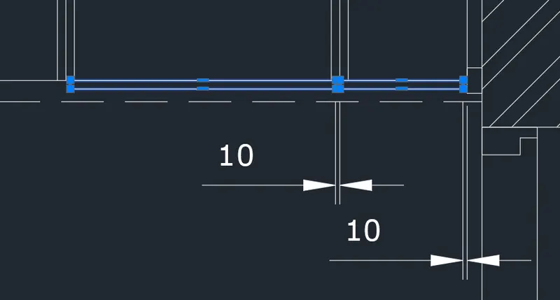
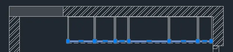
- Add the inside objects using circle, rectangle, copy, text, and fillet tool.
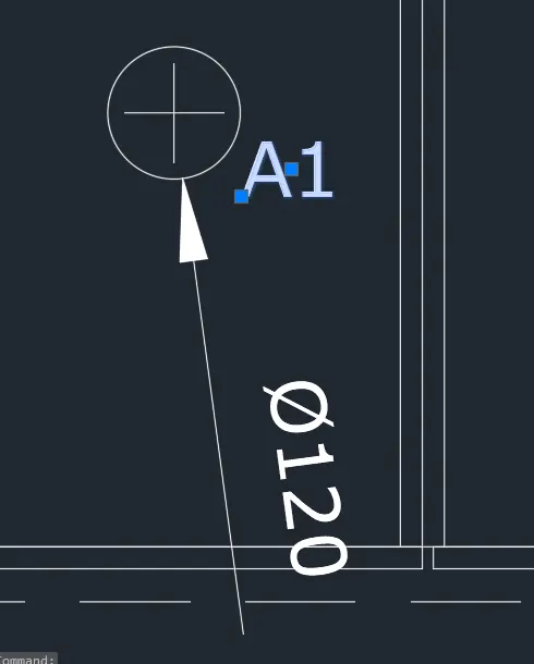
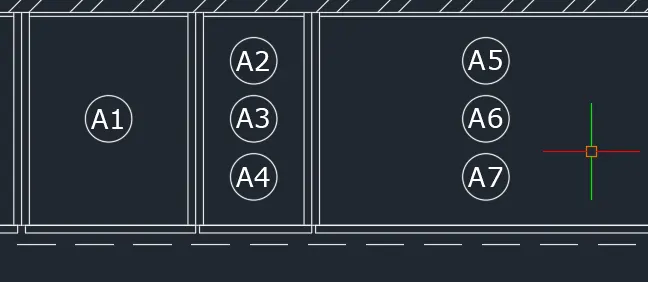
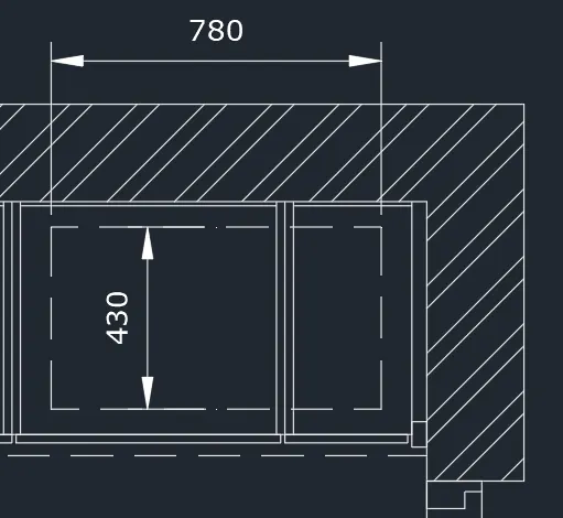
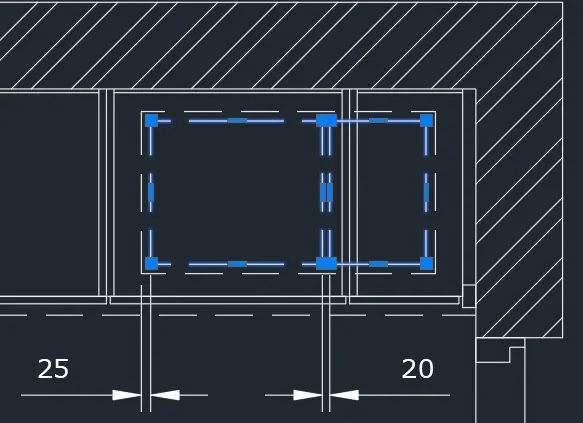
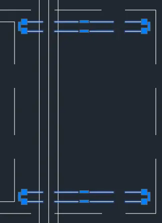
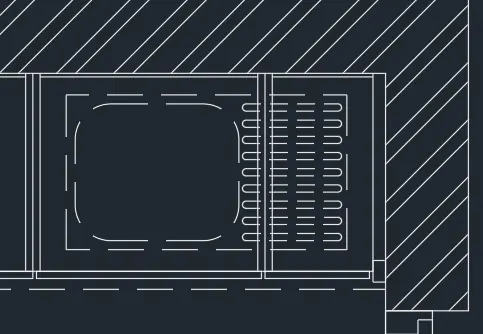
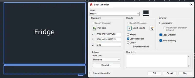
- Use rectangles and lines for the fridge object. Use circle tool as cell for the corner opening.
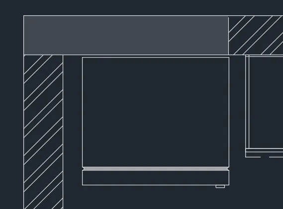
- Add the text to finish.
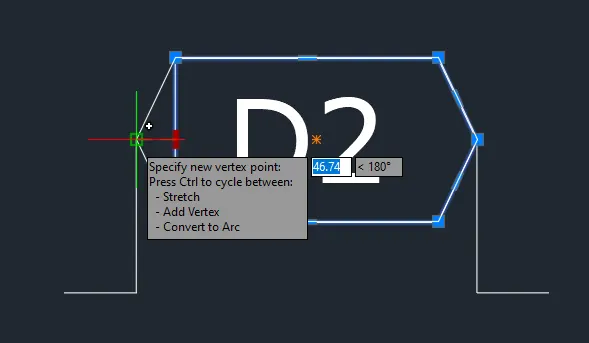
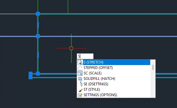
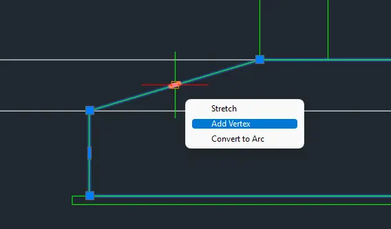
Note: Click the grip and add a new vertex to create the diamond shape enclosing the text D2.
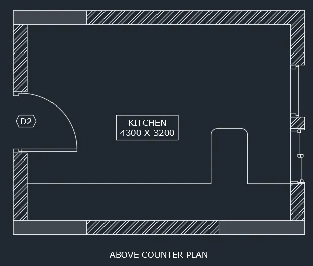
--> Proceed with the above counter.
- Copy any relative lines from below to above plan. Change line types as appropriate.
- Add the border lines for the below part. Trim the line appropriately.
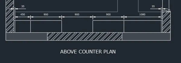
- Create the cabinet walls using offset and trim tool. Thickness is 20mm. Bottom part is 10mm.
- Trim unnecessary lines.
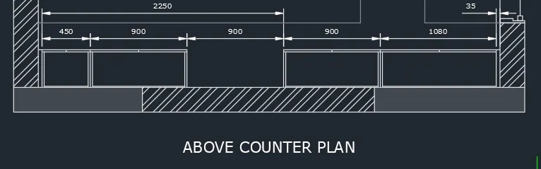
- Create the chimney as below.
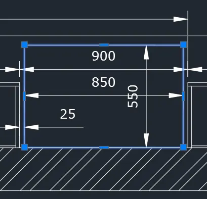
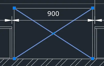
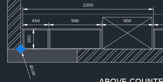
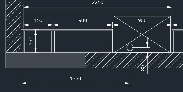
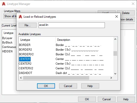
- Load Centerline in the Linetype manager.
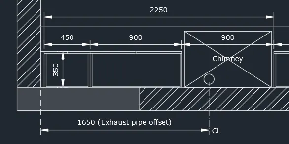
- Explode the dimension line and edit as below. Add the appropriate texts using dtext command.
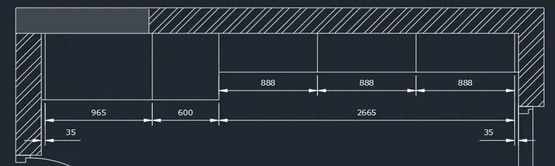
- Proceed with above objects. Create boundary lines. Trim the lines appropriately.
- Create the walls. Thickness = 20mm. Use offset, copy and trim tools.
- Trim and add the rectangles.
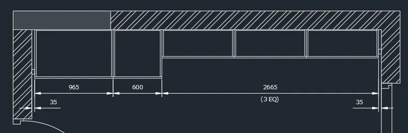
- Add the texts.
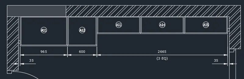
- Add the missing dimensions using dimlinear to finish.
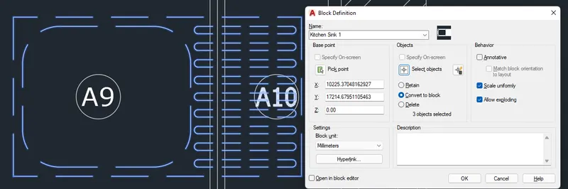
- Convert necessary items to blocks.
FINAL PRODUCT:
***************
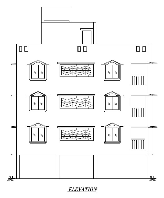
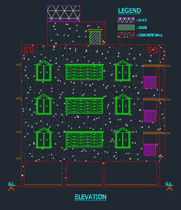
B. Create the elevation of the plan created in the Challenges 7 and apply proper hatch in the walls, doors, windows, and other architectural elements. Refer to the dimensions in Plans and sections in Challenges 7.
PROCEDURE:
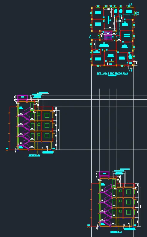
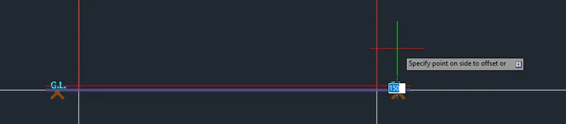
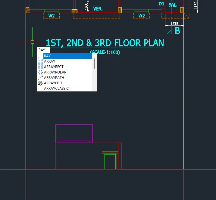
- Project the borders from the plan and existing elevation. The view is South of the Plan. Use Ray or Xline tool.
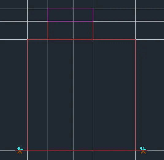
- Create the border.

- Utilize rectangle or line tool to your liking. Then delete the boundary lines when not needed.
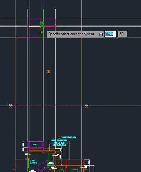
- Start from the top for easier time. Create the O.H.T..
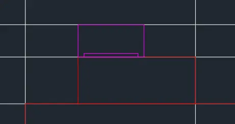
- Proceed with the upper structure (Staircase to rooftop).
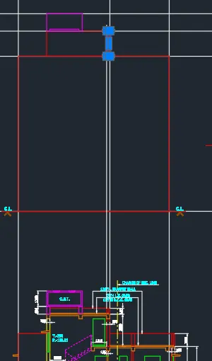
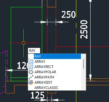
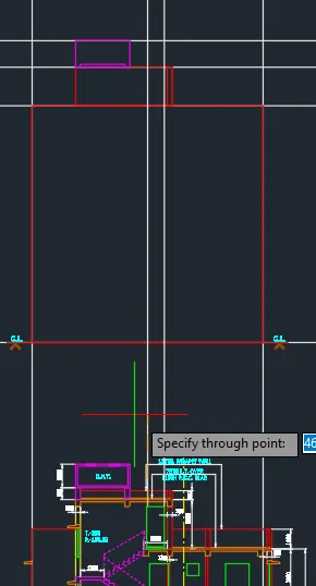
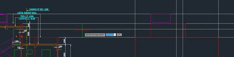
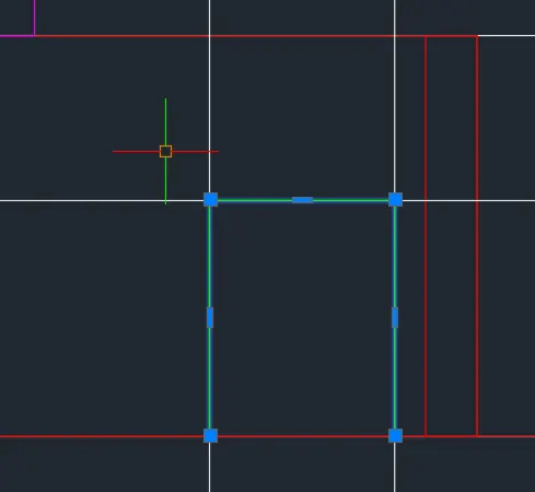
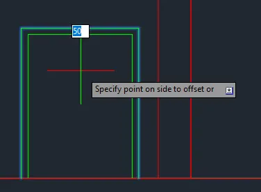
- Create the canopy.
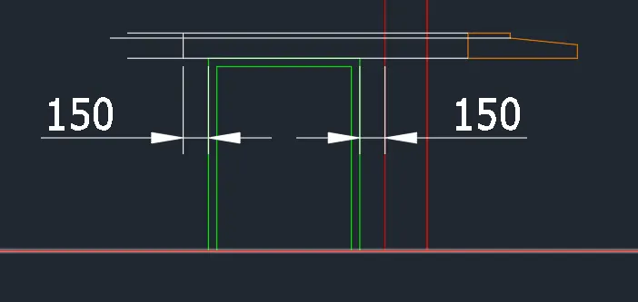
- Trim unnecessary lines after.
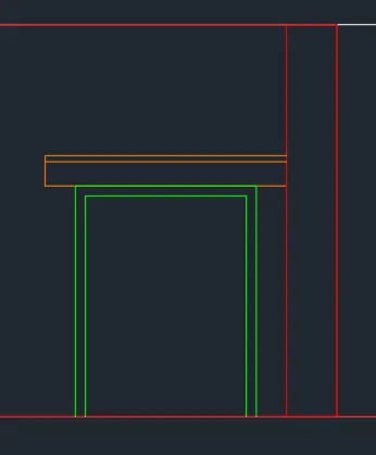
- Top part is finished.
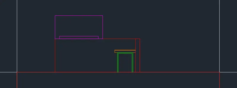
- Proceed to the bottom most part.
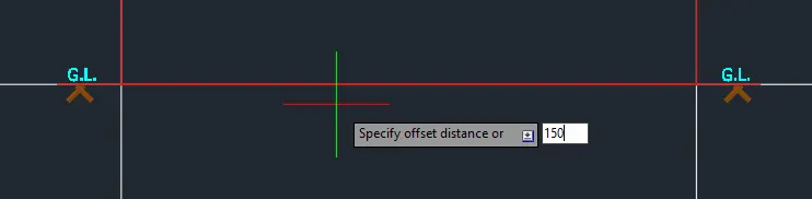


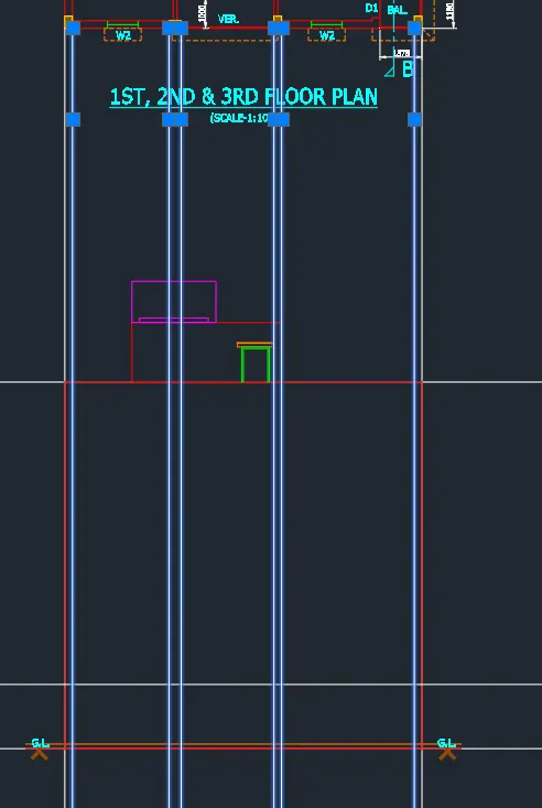
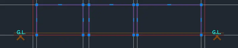
- Project the columns.
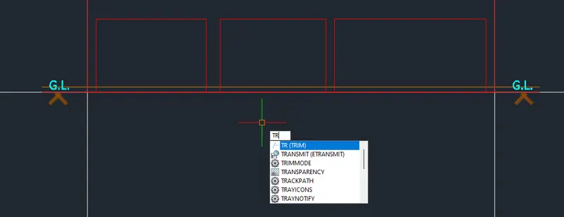
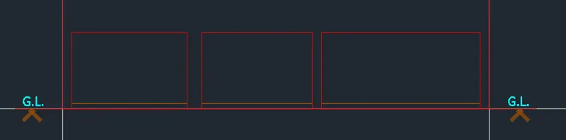
- Copy the canopy from the elevation.
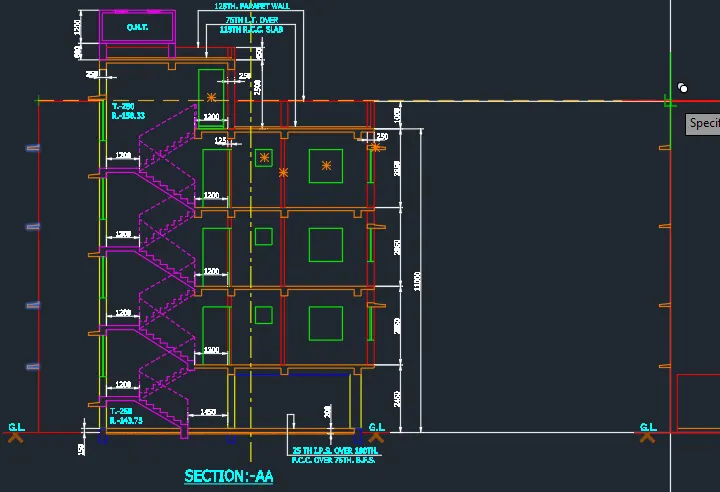
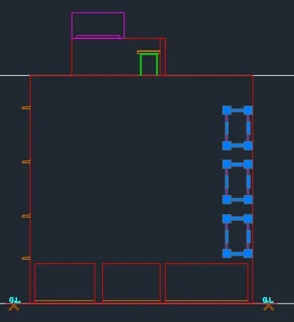
- Proceed with the balcony.
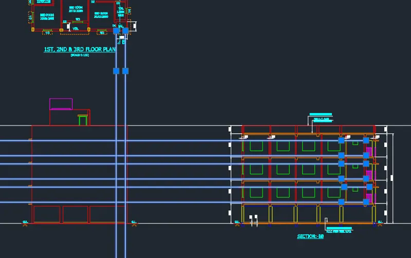

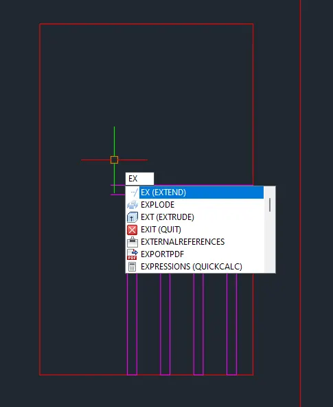
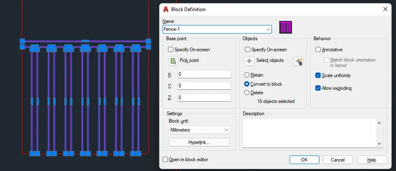
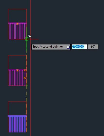
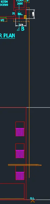
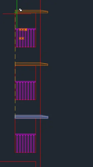
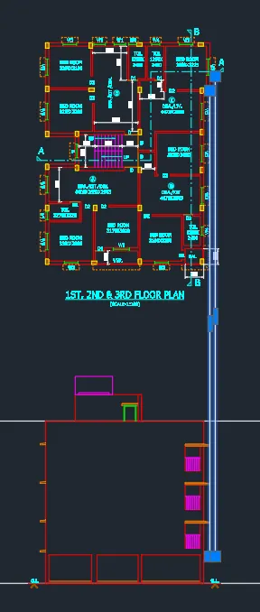
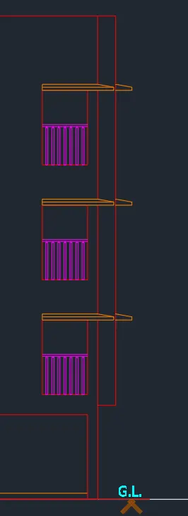
- Proceed with the windows.
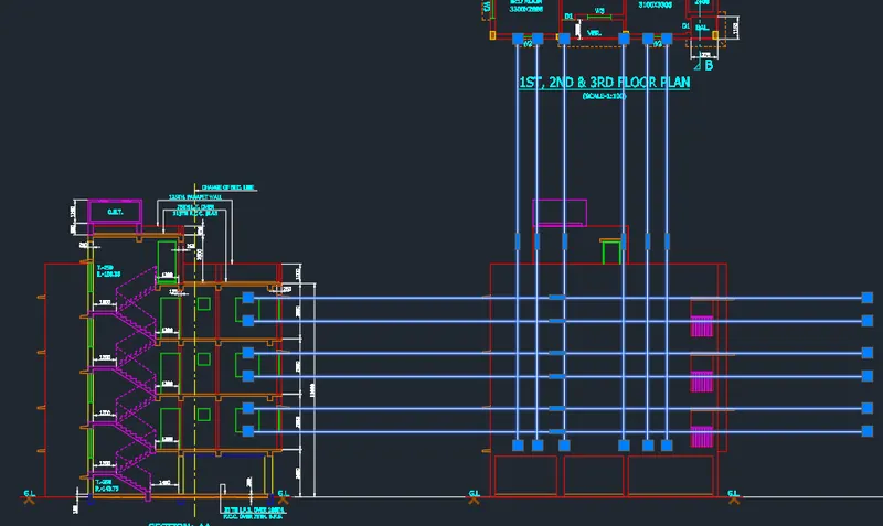
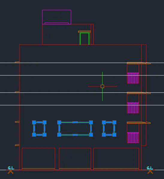
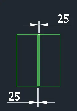
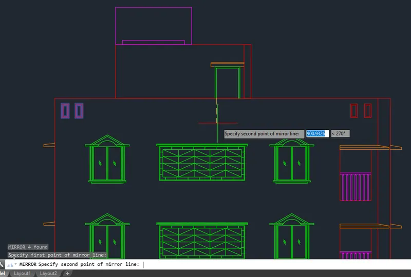
- Create the side window.
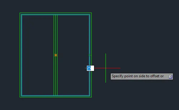
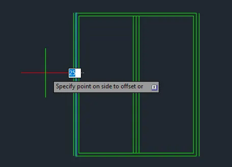
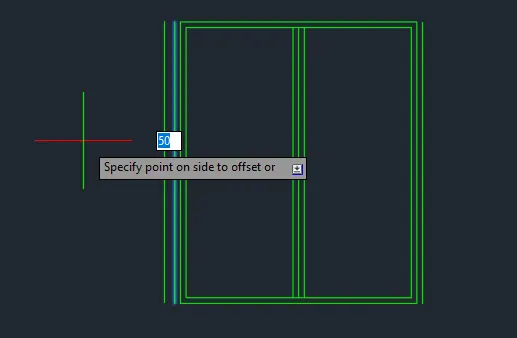
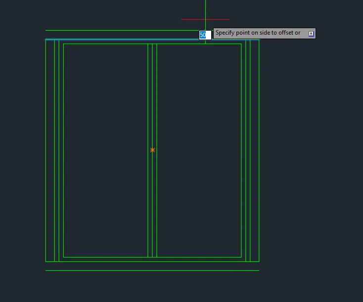
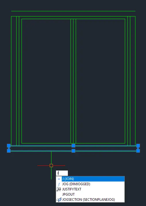

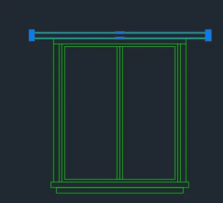
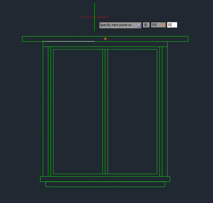
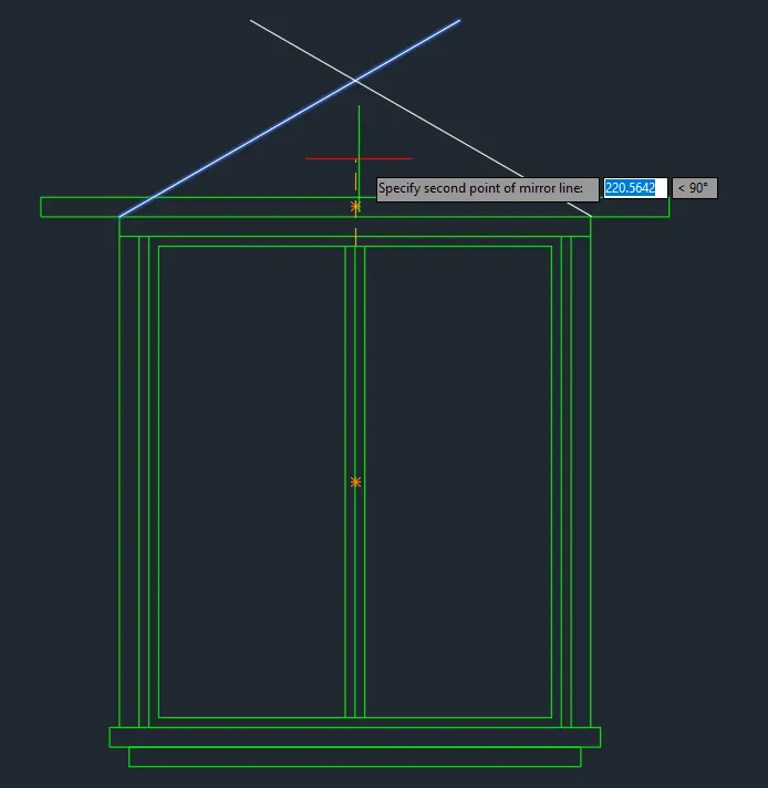
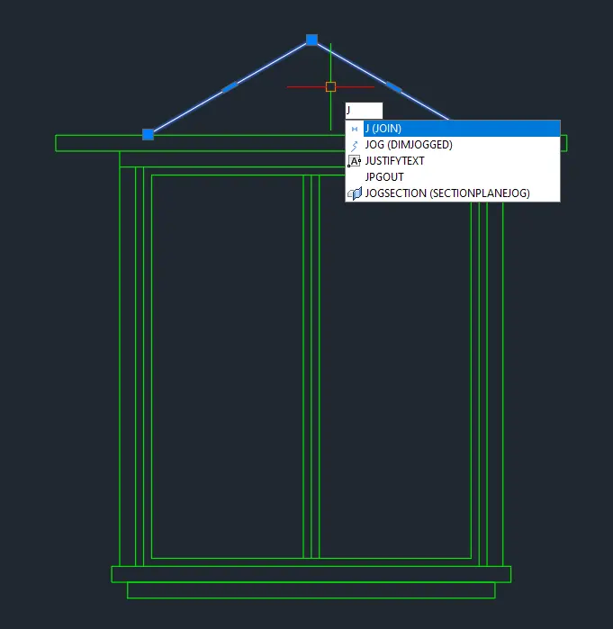
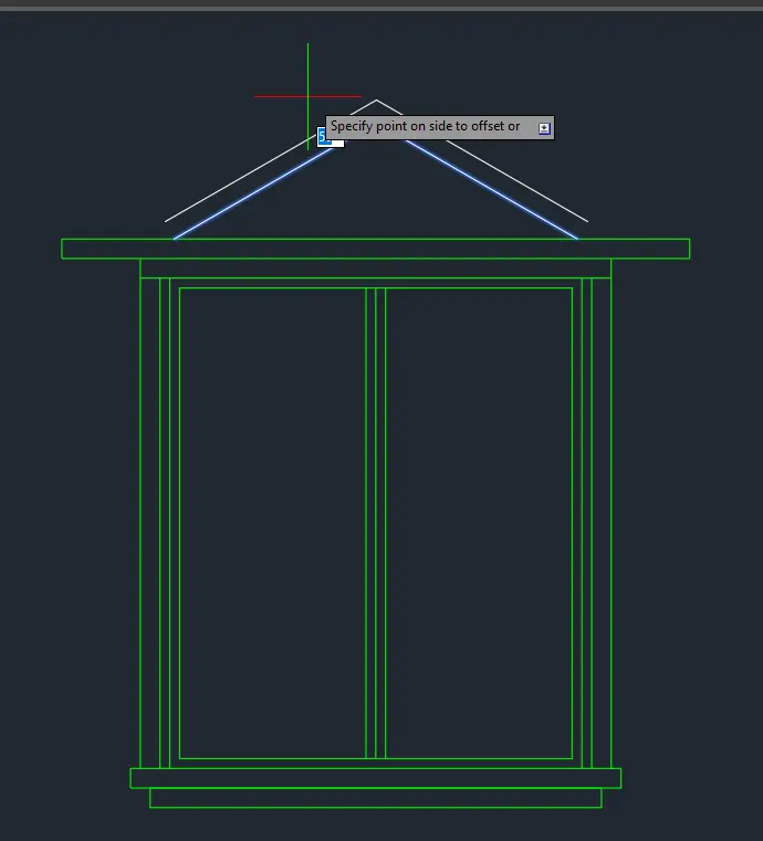
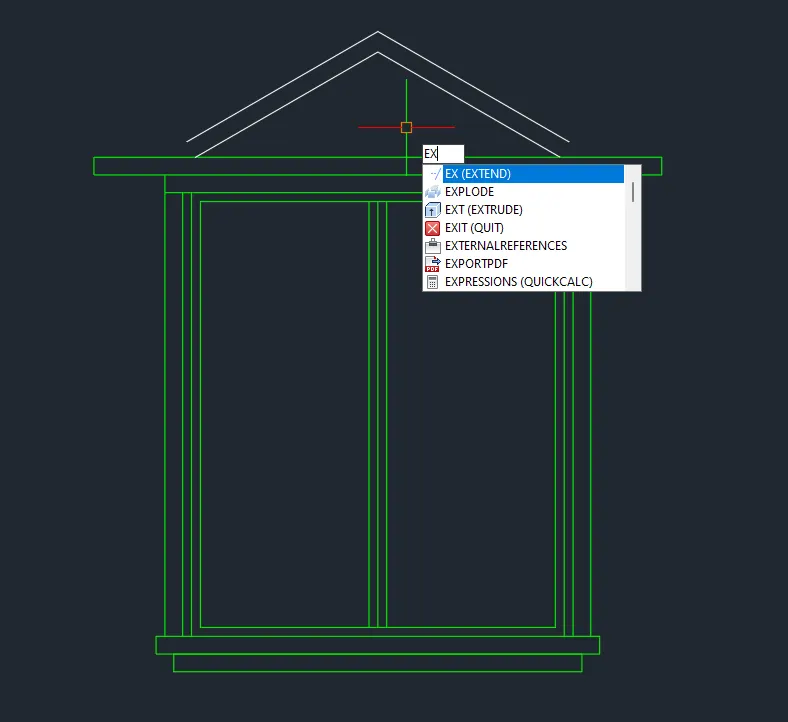
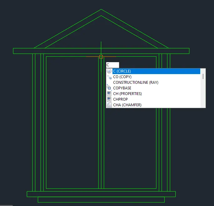
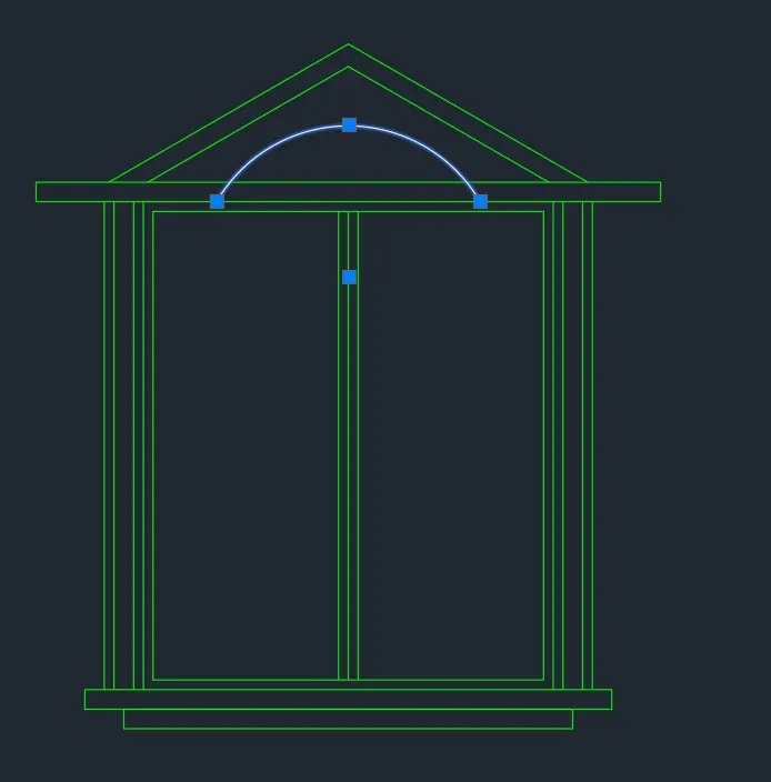
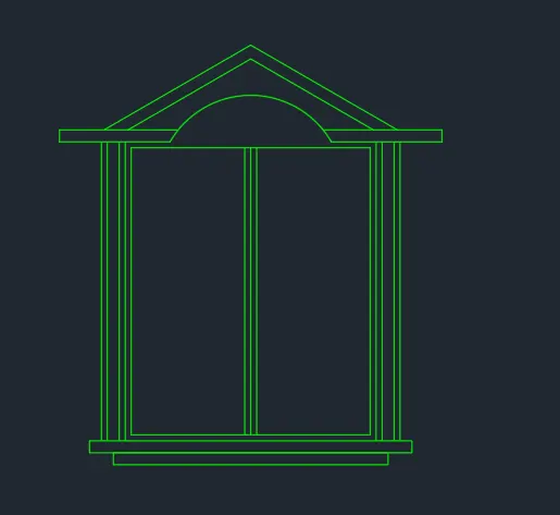
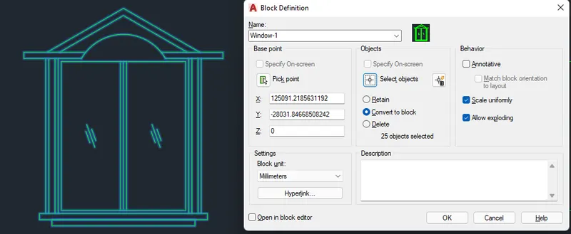
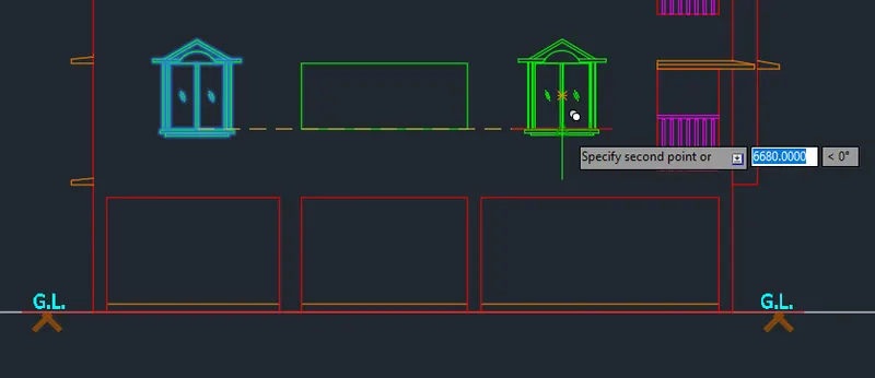
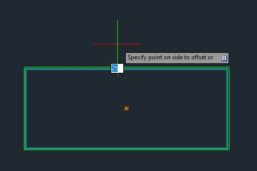
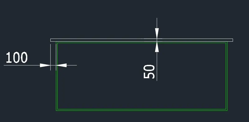
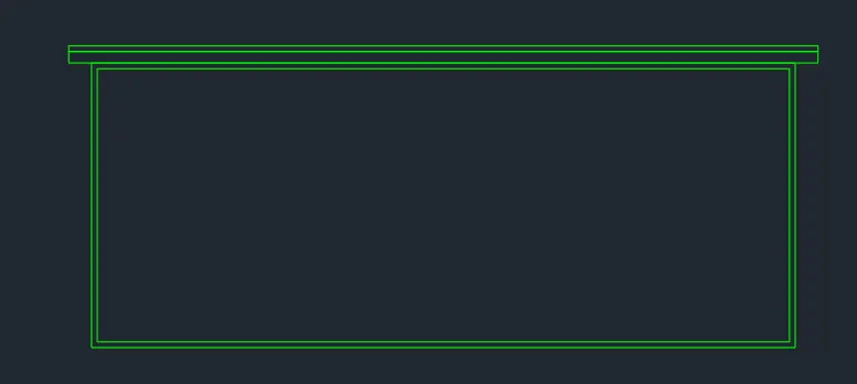
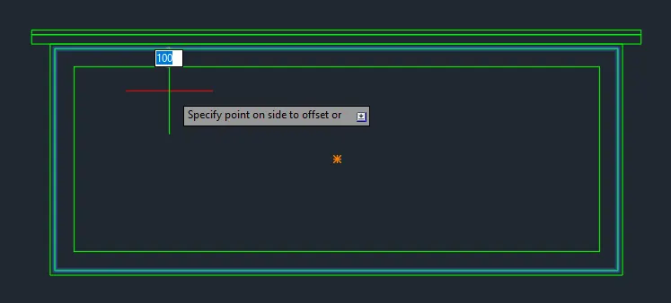
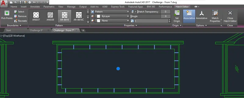
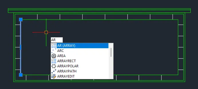
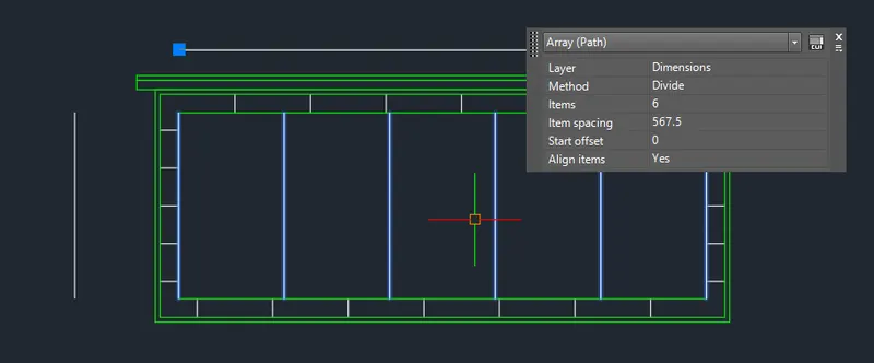
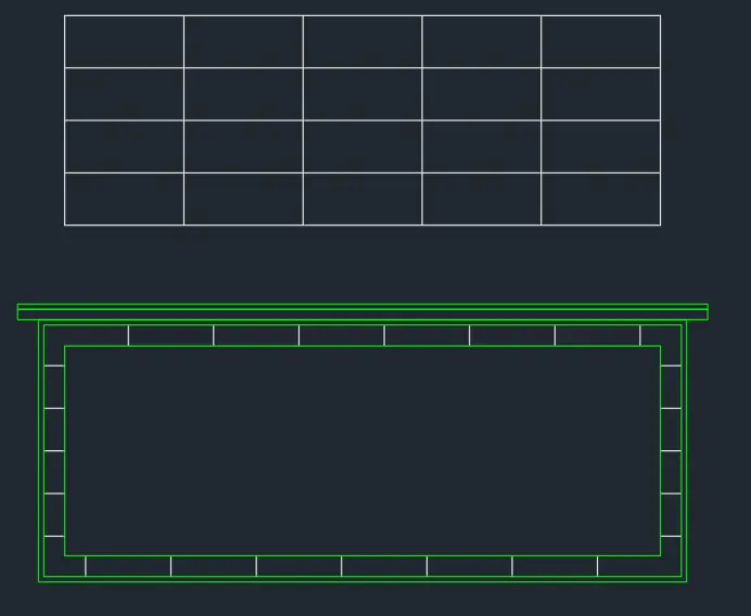
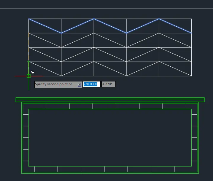
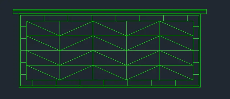
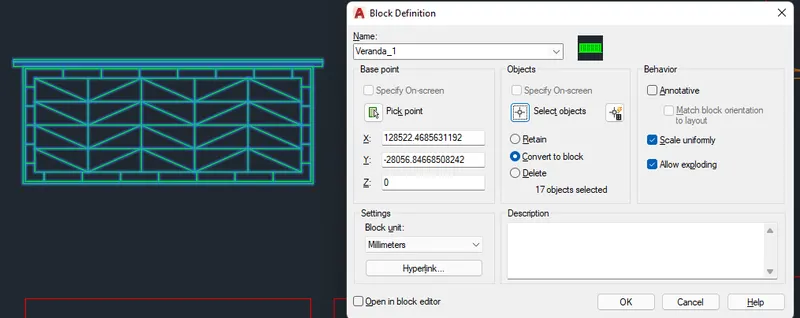
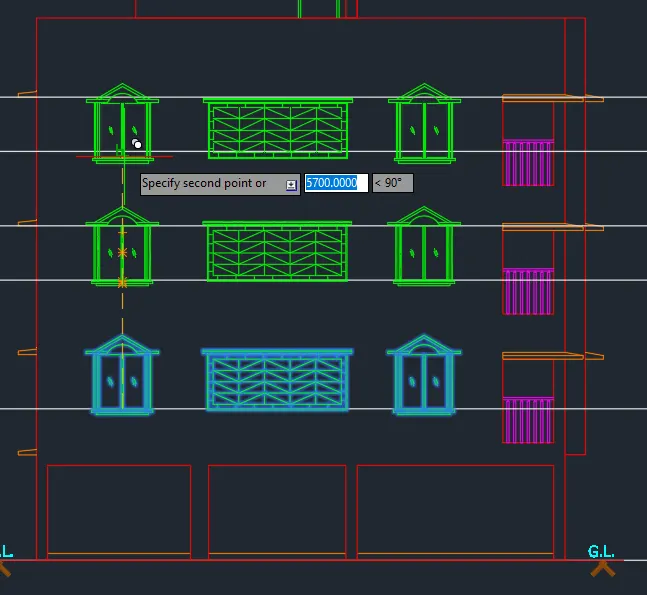
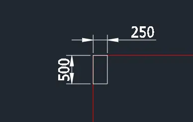
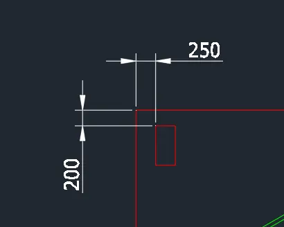
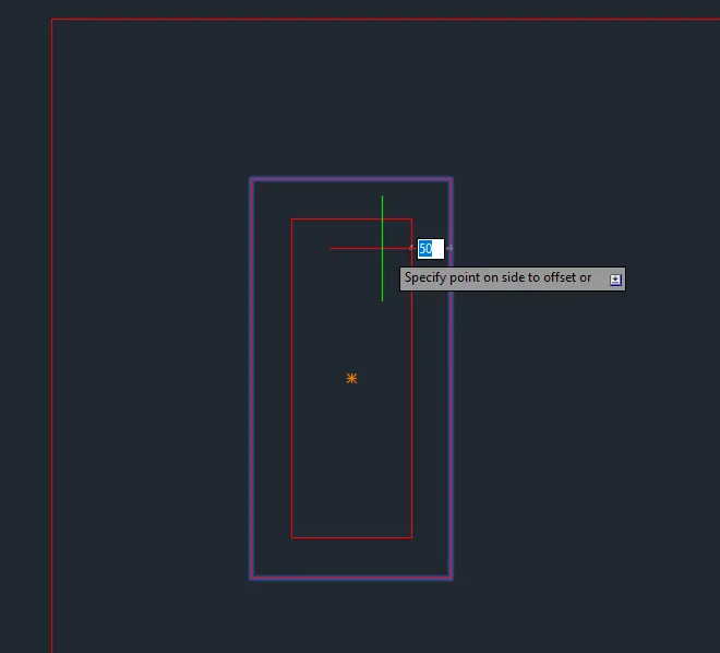
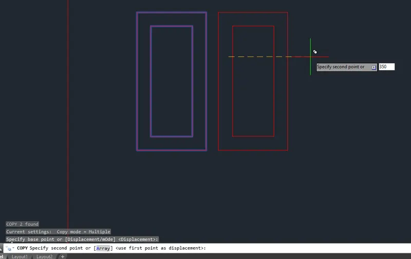
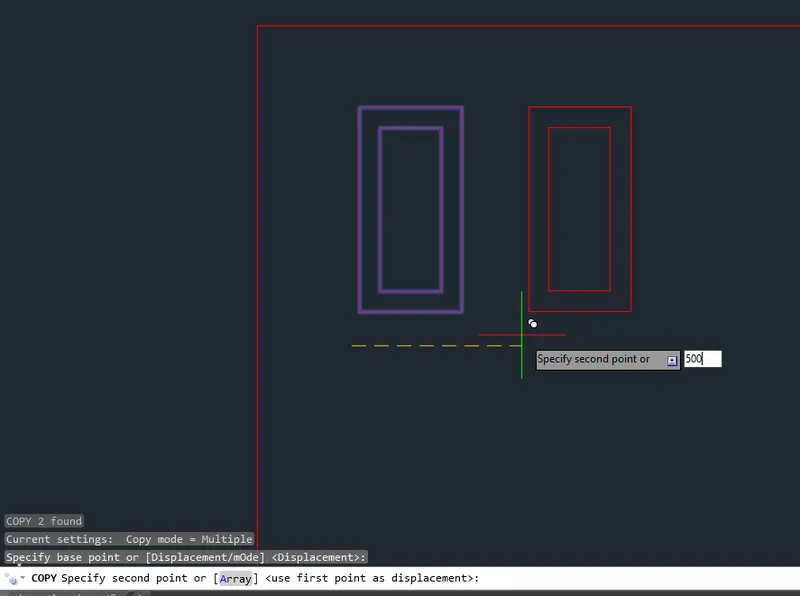
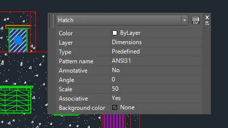
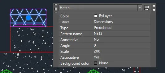
- Add hatches to identify structural elements.
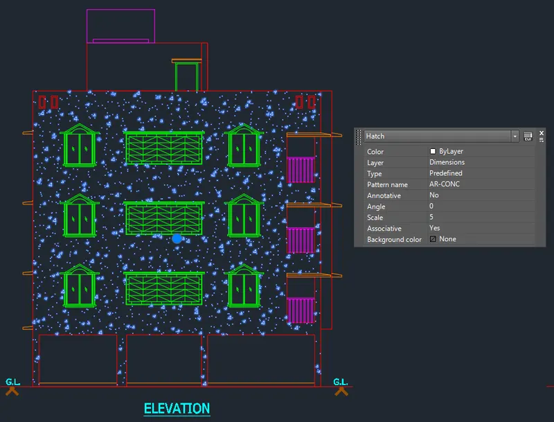
FINAL PRODUCT:
***************
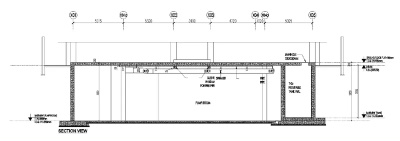
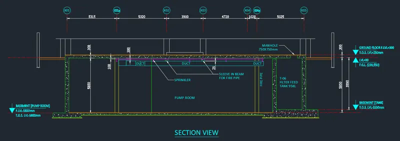
C. Create the section view of an industrial building as shown in Figure. Provide appropriate hatches and dimensions wherever required. Also, provide annotations to the drawing.
PROCEDURE:
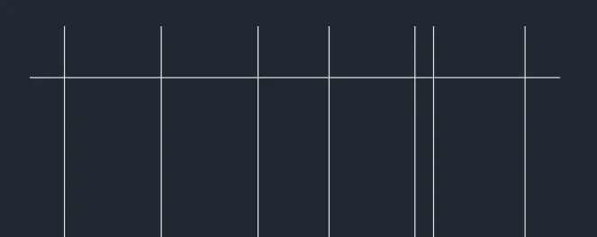
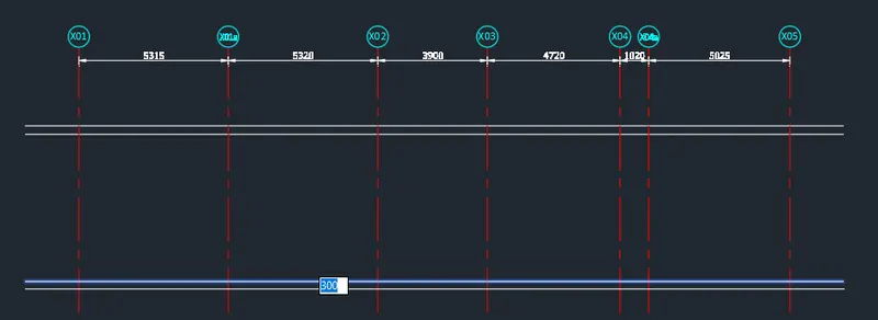
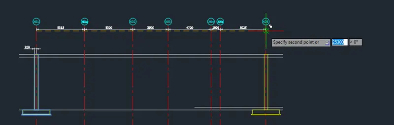
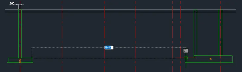
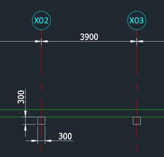
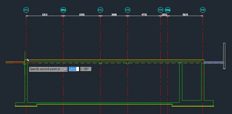
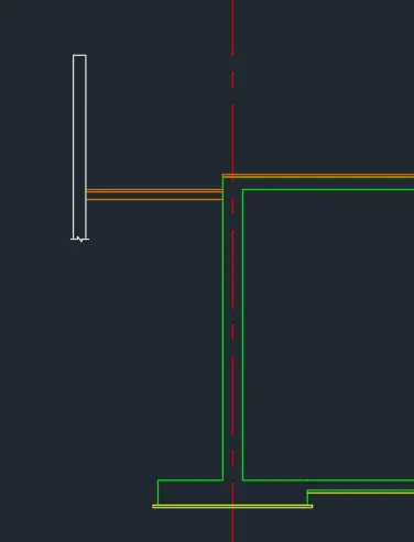
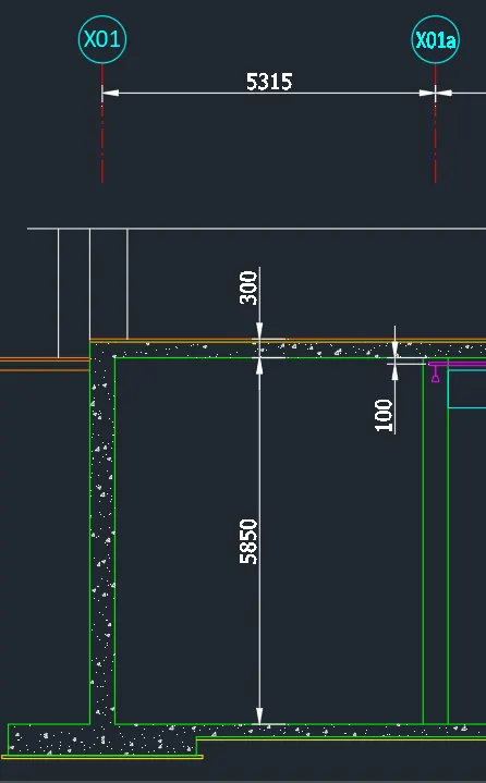
- Create the borders using lines. Start from ground level.
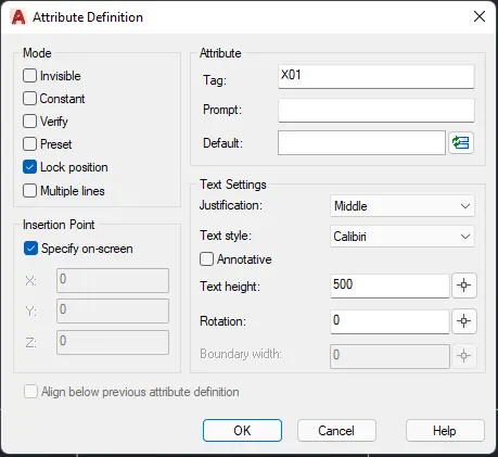
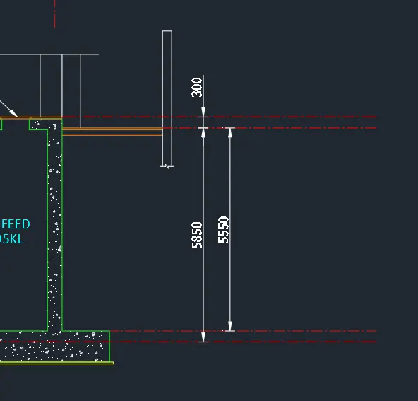
- Add the grid tags and dimensions.
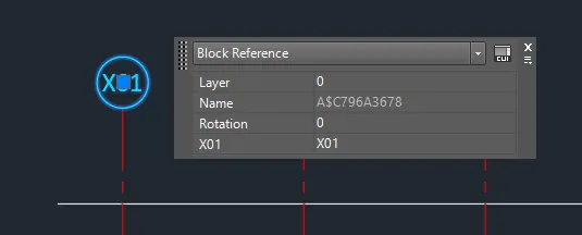
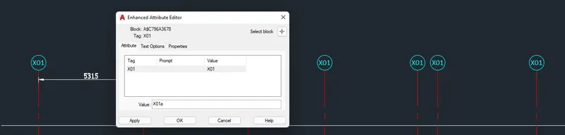

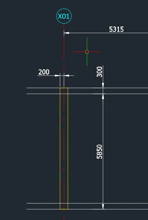
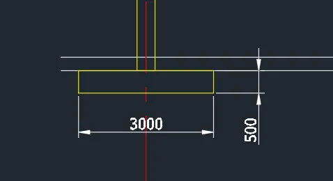
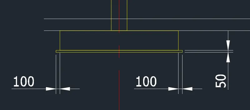
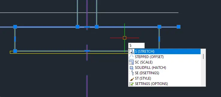
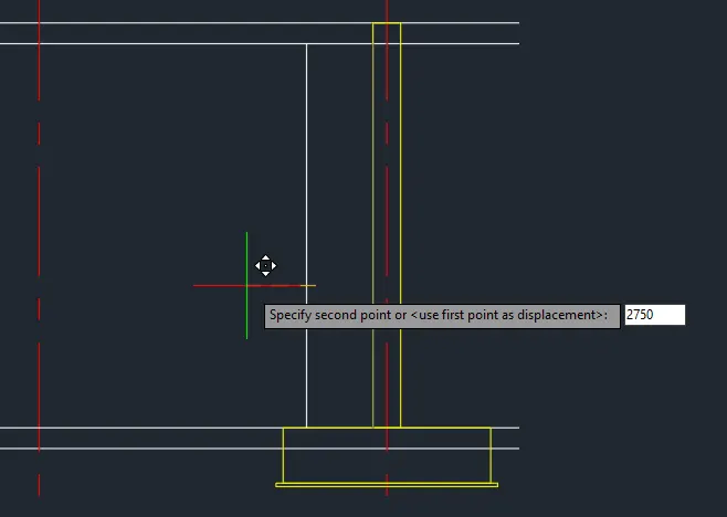
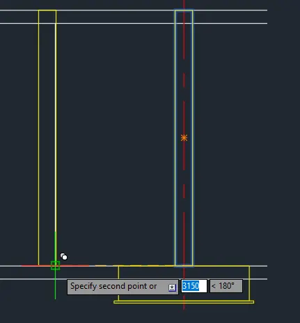
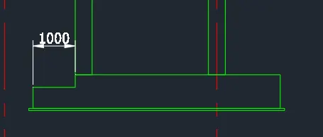
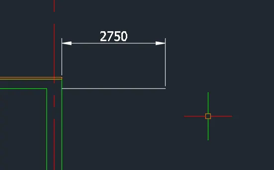
- Add the borders of the wall.
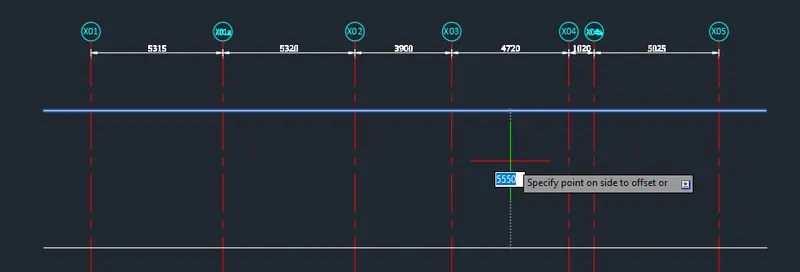
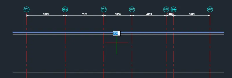
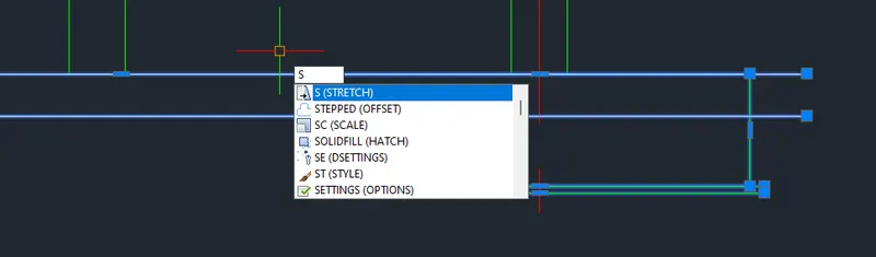
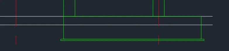
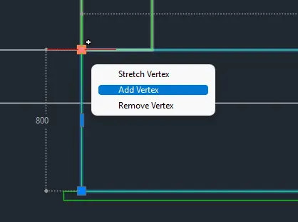
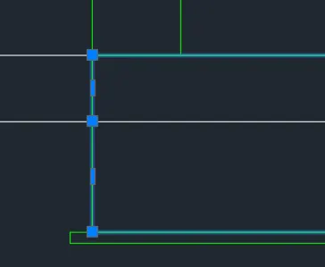

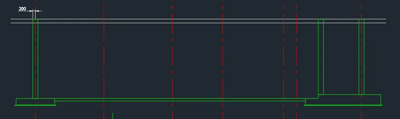
- Trim the unnecessary lines.
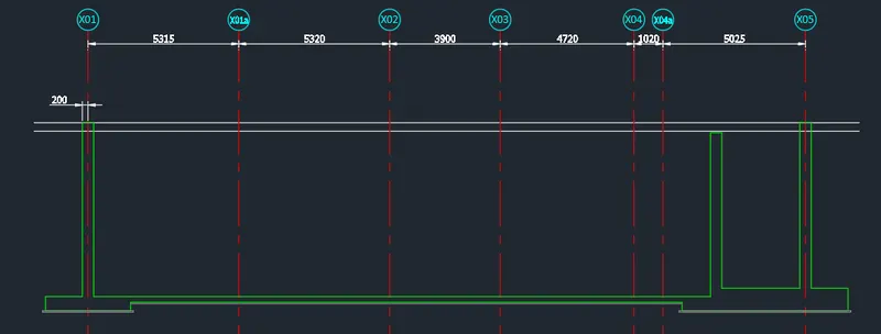

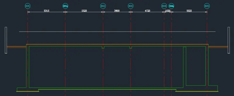
- Do the same procedure for the top slab.
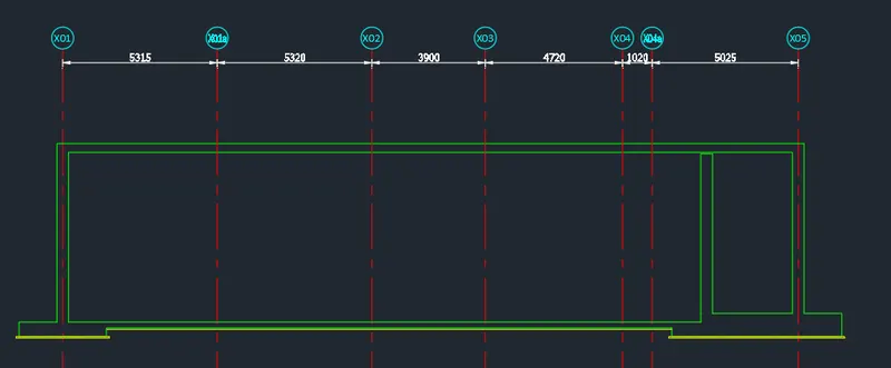

- Add the wall hatch.
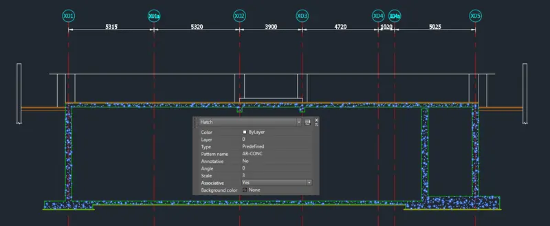
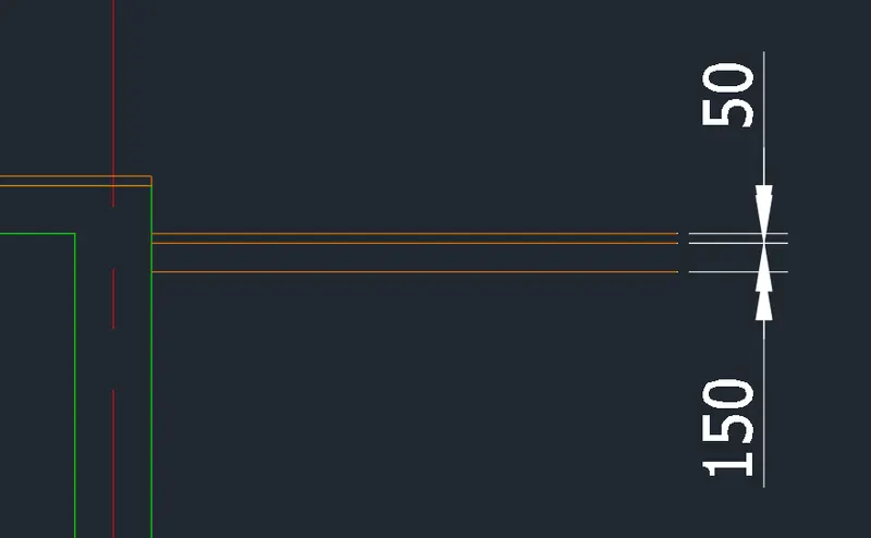
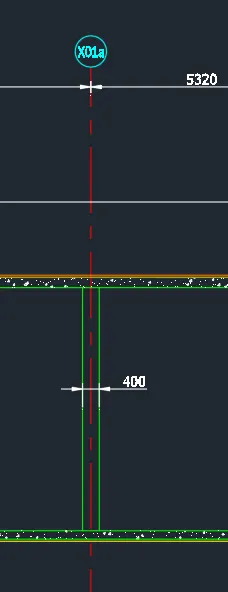
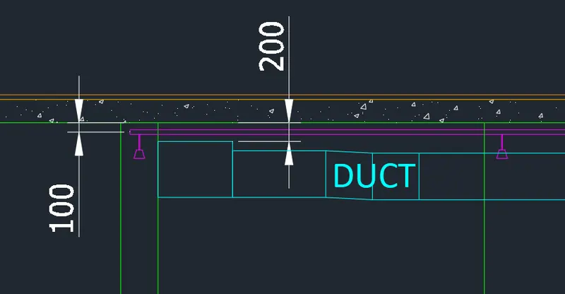
- Add the lines inside.
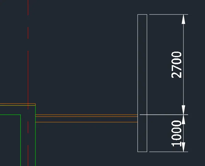
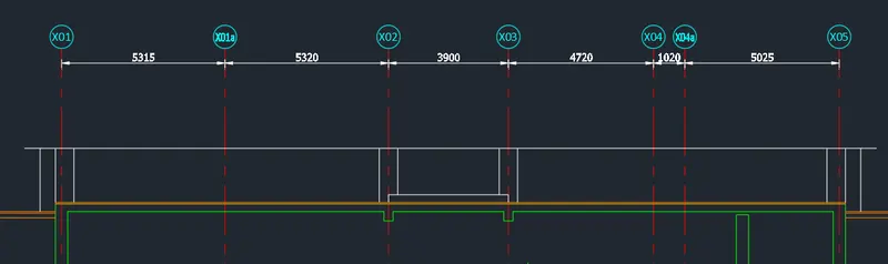
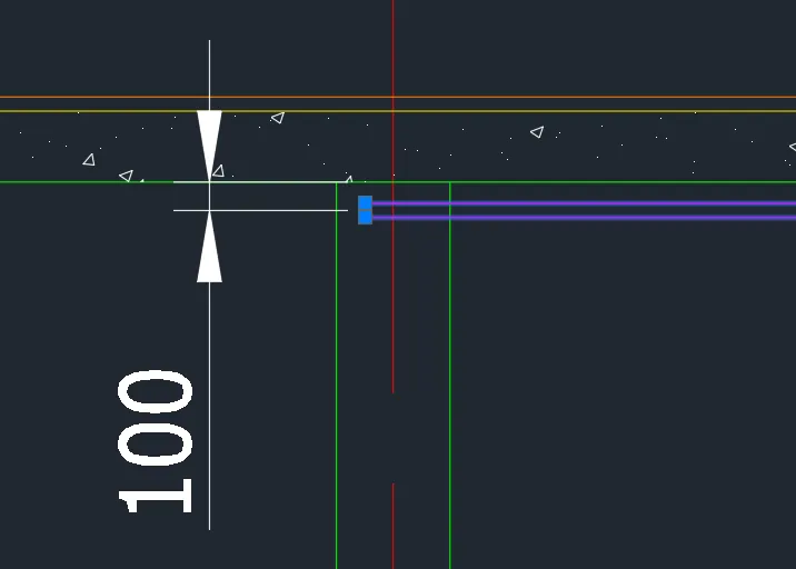
- Add the sprinkler. Use rectangle tool.
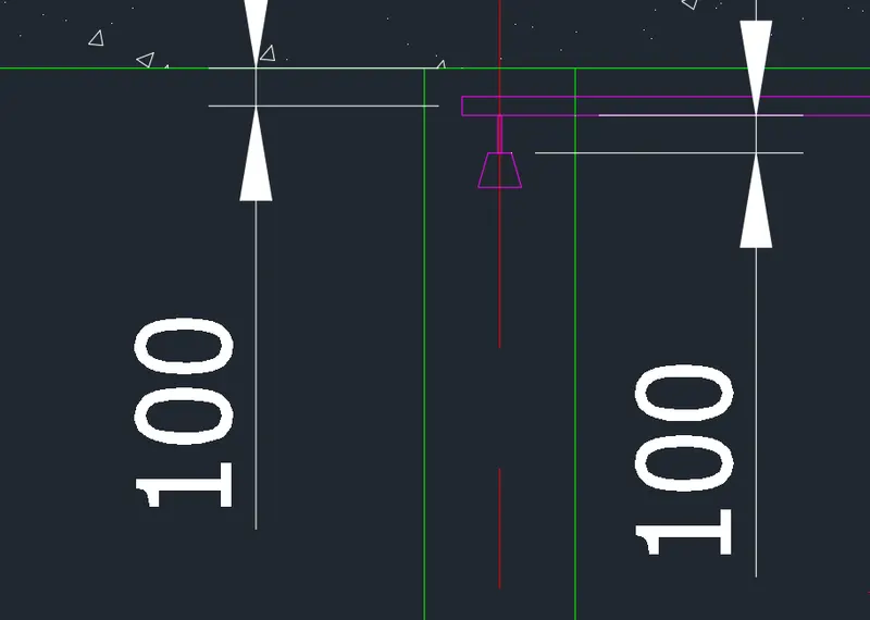
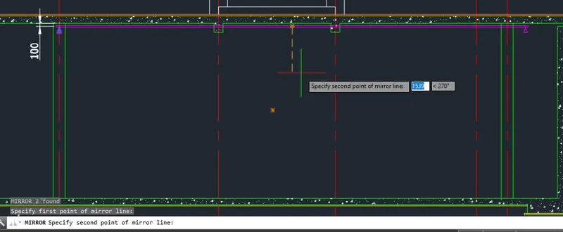
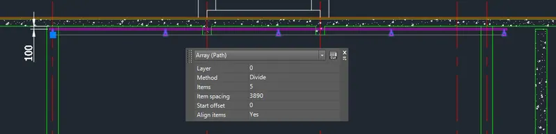
- Create the duct.
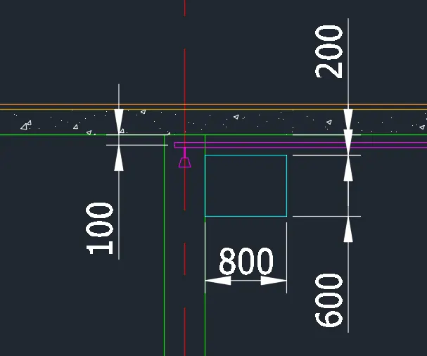
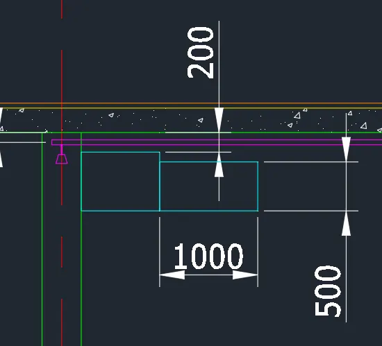
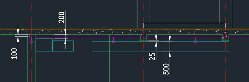
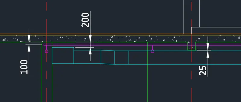
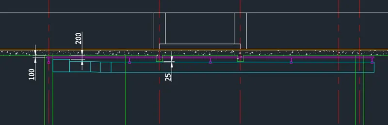
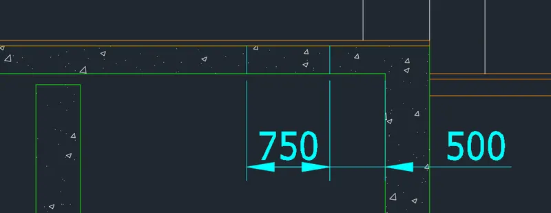
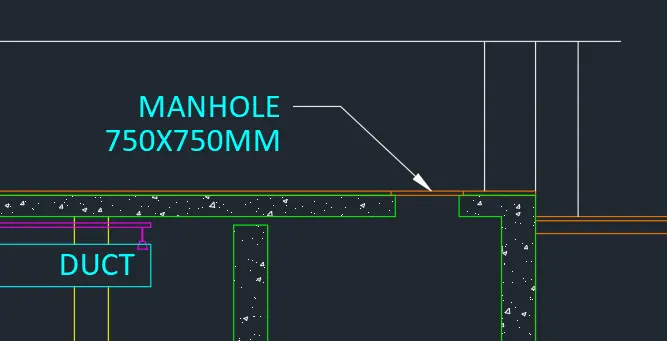
- Add necessary texts and dimensions using dimlinear, dtext, move, and copy tool.
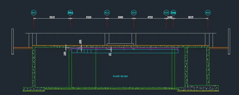
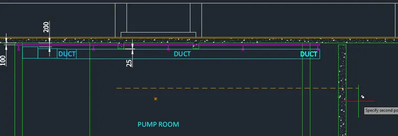
- Add arrows using the leader command.
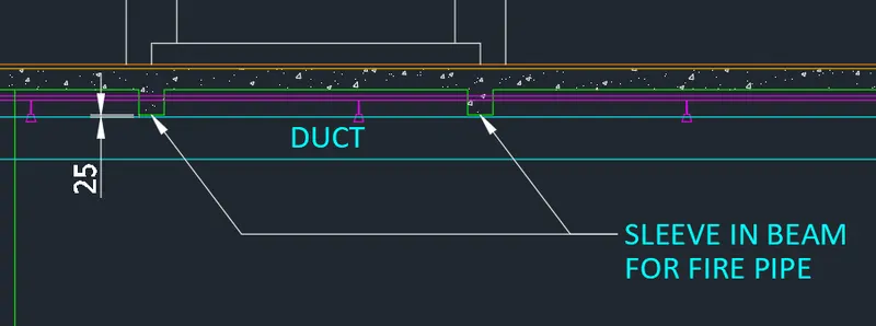
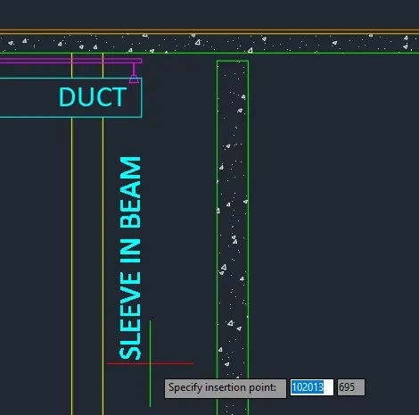
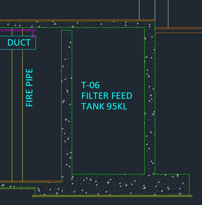
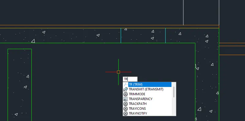
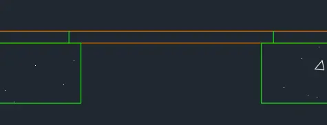
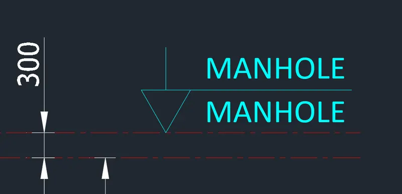
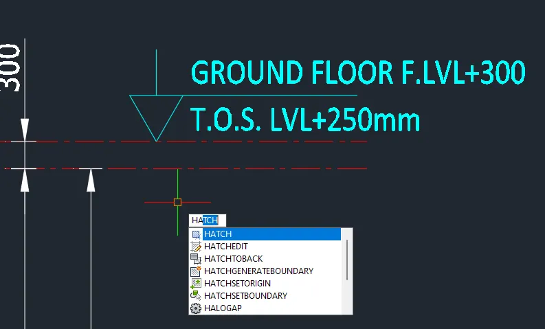
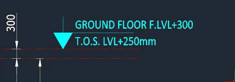
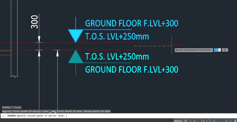
- Add the manhole. Use line and trim command.
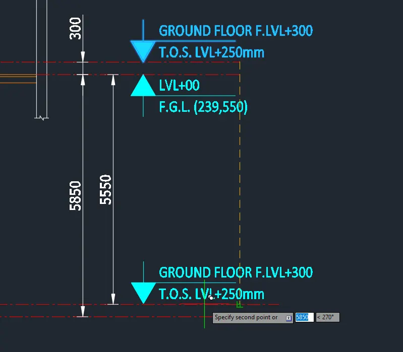
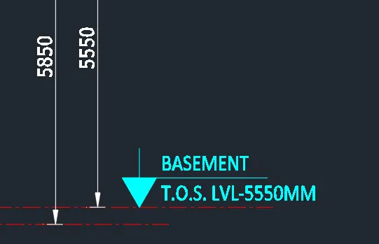
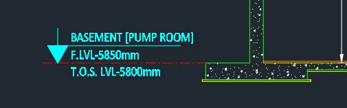
FINAL PRODUCT:
********************************************************
3. Conclusion
***************
The block tool and hatch tool is a convenient tool provided by the AutoCAD software where you can manipulate multiple objects into one objects. It also allows you to store objects in a server which can be used in other sketches. Same goes for the hatching tool which allows the user to create shading or patterns in a given point or object in which it can identify the objects in the sketch.