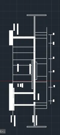
Creating Kitchen layout, Hatching of Architectural elements and sectional view of an Industrial Building in AutoCad
1.
Aim: To draw a given cross section of kitchen using autocad.
procedure: The following steps should be followed as a procedure to draw a given cross section of a kitchen using autocad
- To draw the given cross section of a kitchen in autocad, the following steps should be followed as a procedure. At first open the AutoCAD and set dimensions that the dimensions are in mm.
- Then enter the Line command in AutoCAD and after that enter the first point of the given diagram as that line should be started at the point in the coordinate system.
- Draw a rectangle using the autocad command enter the dimensions as per the given requirement as per the table.
- Then with that point draw a rectangle using rectangle command using the dimensions of the rectangle as length is 4300 and width is 2300
- by using the offset command in autocad make offsset of 480 for the outer wall ie enter the dimension of the offset as 480.
- then select the last line of the rectangle and make offset of 12 ie the width of the both sides of the cross section of a wardrobe by using the offset command in autocad.
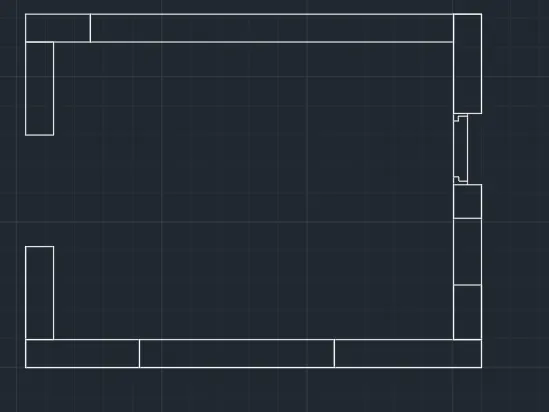
- next make offset of that line 600 ie the width of the inner lines is equal to 450, ie enter the offset command and give the width of 300.
- next make the offset of the line left corner of the rectangle to get the length of the inner spaces of the wardrobe by using the offset command in autocad give the offset lenth as 300 delete the unwanted lines by using the trim command in autocad.
- next make the offset of the line left corner of the rectangle to get the length of the one of the bathrooms by using the offset command in autocad give the offset lenth as 450.
- next make the offset of the line right corner of the rectangle to get the length of the another bathroom by using the offset command in autocad give the offset lenth as 900.
- next make offset of that line 450 ie the width of the inner wall is equal to 300 ie enter the offset command and give the width of 450
- delete the unwanted lines by using the trim command in autocad.
- next make the offset of the line right corner of the rectangle to get the length of the another bathroom by using the offset command in autocad give the offset lenth as 945.
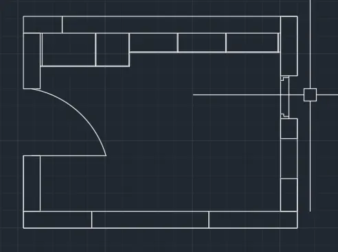
- to draw the door by using the autocad commands that by line command we can draw the line and by arc command we can draw the arc and by rectangle command we can draw the chouckets and then trim the unwanted lines. repeat the process for each and every door point side as per the required floor plan.
- enter the dimensions of the rooms as per the given dimensions using the Multi text command in autocad and enter the dimensions wich is required in the given floor plan to gte the required floor plan of the bathrooms and vanity and all other rooms.
- next make offset of that line 600 ie the width of the inner lines is equal to 450, ie enter the offset command and give the width of 300.
- next make the offset of the line left corner of the rectangle to get the length of the inner spaces of the wardrobe by using the offset command in autocad give the offset lenth as 300 delete the unwanted lines by using the trim command in autocad.
- next make the offset of the line left corner of the rectangle to get the length of the one of the bathrooms by using the offset command in autocad give the offset lenth as 450.
- next make the offset of the line right corner of the rectangle to get the length of the another bathroom by using the offset command in autocad give the offset lenth as 900.
- next make offset of that line 450 ie the width of the inner wall is equal to 300 ie enter the offset command and give the width of 450
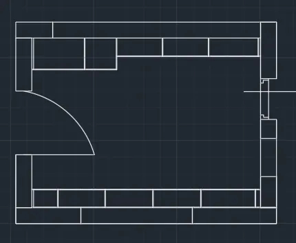
- give the dimensions of that usimg the dimensions settings in autocad and then make the settings in the annatation as shown in the figure below.
- and by using the multitext command or by copying the text which has been present in the another column the header text has been written size or edited and edit the text as per the required and paste it on the row which has been present and edit the text and place the texting height as per the required table as shown in the figure below.
- edit the text as per the required and paste it on the row which has been present and edit the text and place the texting height as per the required table as shown in the figure below.
- to draw the door by using the autocad commands that by line command we can draw the line and by arc command we can draw the arc and by rectangle command we can draw the chouckets and then trim the unwanted lines. repeat the process for each and every door point side as per the required kitchen cross section.
- enter the dimensions of the kitchen cross section as per the given dimensions using the Multi text command in autocad and enter the dimensions wich is required in the given floor plan to gte the required floor plan of the bathrooms and vanity and all other rooms.
- and by using the multitext command or by copying the text which has been present in the another column the header text has been written sizes of the rooms or edited and edit the text as per the required and paste it on the row which has been present and edit the text and place the texting height as per the required table as shown in the figure below.
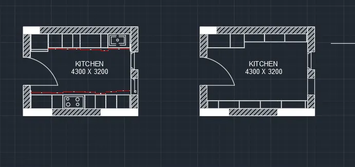
- To make the table as a single block then select the block option and create the block to create the block select on create block on view option and then for creating a block we have to pick the point ie the reference point and then select the lines or the objects which has to make block and then if we want to make annotative make annottive and then press ok.
- here to create block click on create block option and create the block name in the block name option then pick up the reference point and then slect the texts and lines which have to make block and then press ok to crate the block.
- Now, you need to tell AutoCAD what the insertion point should be. In other words, when you place the block, the point about which the block appears at your cursor Click the Select Objects button and select the objects you want to be stored in the block.
- To make the table as a single block then select the block option and create the block to create the block select on create block on view option and then for creating a block we have to pick the point ie the reference point and then select the lines or the objects which has to make block and then if we want to make annotative make annottive and then press ok.
- here to create block click on create block option and create the block name in the block name option then pick up the reference point and then slect the texts and lines which have to make block and then press ok to crate the block.
- Now, you need to tell AutoCAD what the insertion point should be. In other words, when you place the block, the point about which the block appears at your cursor Click the Select Objects button and select the objects you want to be stored in the block.
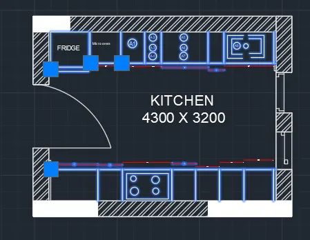
- To make the table as a single block then select the block option and create the block to create the block select on create block on view option and then for creating a block we have to pick the point ie the reference point and then select the lines or the objects which has to make block and then if we want to make annotative make annottive and then press ok.
- here to create block click on create block option and create the block name in the block name option then pick up the reference point and then slect the texts and lines which have to make block and then press ok to crate the block.
- Now, you need to tell AutoCAD what the insertion point should be. In other words, when you place the block, the point about which the block appears at your cursor Click the Select Objects button and select the objects you want to be stored in the block.
- To make the table as a single block then select the block option and create the block to create the block select on create block on view option and then for creating a block we have to pick the point ie the reference point and then select the lines or the objects which has to make block and then if we want to make annotative make annottive and then press ok.
- here to create block click on create block option and create the block name in the block name option then pick up the reference point and then slect the texts and lines which have to make block and then press ok to crate the block.
- Now, you need to tell AutoCAD what the insertion point should be. In other words, when you place the block, the point about which the block appears at your cursor Click the Select Objects button and select the objects you want to be stored in the block.
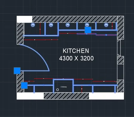
2.
To draw a given floor plan elevation cross section view using autocad.
procedure: The following steps should be followed as a procedure to draw a given floor plan elevation cross section view using autocad
- To draw the given floor plan elevation cross section view in autocad, the following steps should be followed as a procedure. At first open the AutoCAD and set dimensions that the dimensions are in mm.
- Then enter the Line command in AutoCAD and after that enter the first point of the given diagram as that line should be started at the point in the coordinate system.
- Then with that point draw a rectangle using rectangle command using the dimensions of the rectangle as length is 2850 and width is 2850.
- by using the offset command in autocad make offsset of 230 for the outer wall ie enter the dimension of the offset as 230.
- then select the last line of the rectangle and make offset of 2550 ie the width of the both bedrooms by using the offset command in autocad.
- next make offset of that line as per the measuement taken ie the width of the inner lines is equal per the measuement taken, ie enter the offset command and give the width ans in the line seetings select the required line type to change the line type .
- next make the offset of the line left corner of the rectangle to get the length of the inner spaces of the wardrobe by using the offset command in autocad give the offset lenth as per the measuement taken delete the unwanted lines by using the trim command in autocad in the line seetings select the required line type to change the line type.
- next make the offset of the line left corner of the rectangle to get the length of the one of the liner lines of the column by using the offset command in autocad give the offset lenth as per the measuement taken in the line seetings select the required line type to change the line type.
- next make the offset of the line right corner of the rectangle to get the length of the another in the line seetings select the required line type to change the line type by using the offset command in autocad give the offset lenth as 1200 in the line seetings select the required line type to change the line type.
- next make offset of that line per the measuement taken ie the width of the inner wall is equal to ie enter the offset command and give the width of in the line seetings select the required line type to change the line type
- delete the unwanted lines by using the trim command in autocad in the line seetings select the required line type to change the line type.
- next make the offset of the line right corner of the rectangle to get the length of the another in the line seetings select the required line type to change the line type by using the offset command in autocad give the offset lenth as in the line seetings select the required line type to change the line type.
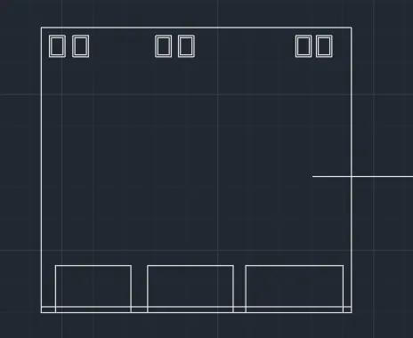
- next make the offset of the line left corner of the rectangle to get the length of the one of the liner lines of the column by using the offset command in autocad give the offset lenth as per the measurement taken in the line seetings select the required line type to change the line type.
- next make the offset of the line right corner of the rectangle to get the length of the another in the line seetings select the required line type to change the line type by using the offset command in autocad give the offset lenth as per the measurement taken in the line seetings select the required line type to change the line type.
- next make offset of that line ie the width of the inner wall is equal to per the measurement taken ie enter the offset command and give the width of in the line seetings select the required line type to change the line type
- place the columns as per the required places and then make that copy all the columns and rotate as per the required schdule column cross section placing.
- delete the unwanted lines by using the trim command in autocad in the line seetings select the required line type to change the line type.
- next make the offset of the line right corner of the rectangle to get the length of the another in the line seetings select the required line type to change the line type by using the offset command in autocad give the offset lenth as in the line seetings select the required line type to change the line type.
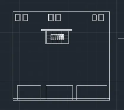
- taken in the line seetings select the required line type to change the line type.
- next make the offset of the line right corner of the rectangle to get the length of the another in the line seetings select the required line type to change the line type by using the offset command in autocad give the offset lenth as per the measurement taken in the line seetings select the required line type to change the line type.
- next make offset of that line ie the width of the inner wall is equal to per the measurement taken ie enter the offset command and give the width of in the line seetings select the required line type to change the line type
- place the columns as per the required places and then make that copy all the columns and rotate as per the required schdule column cross section placing.
- delete the unwanted lines by using the trim command in autocad in the line seetings select the required line type to change the line type.
- next make the offset of the line right corner of the rectangle to get the length of the another in the line seetings select the required line type to change the line type by using the offset command in autocad give the offset lenth as in the line seetings select the required line type to change the line type.
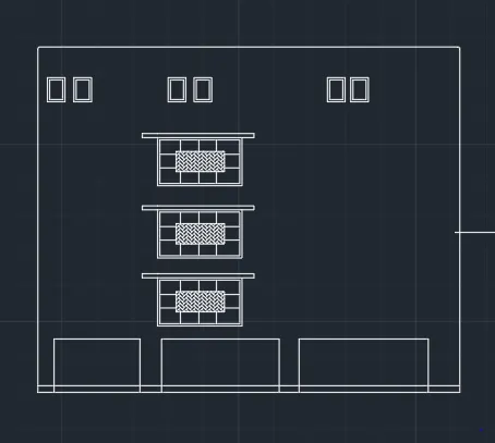
- next make offset of that line as per the diagram ie the width of the inner lines is equal to some dimensions, ie enter the offset command and give the width of ans in the line seetings select the required line type to change the line type .
- next make the offset of the line left corner of the rectangle to get the length of the inner spaces of the wardrobe by using the offset command in autocad give the offset lenth as delete the unwanted lines by using the trim command in autocad in the line seetings select the required line type to change the line type.
- next make the offset of the line left corner of the rectangle to get the length of the one of the liner lines of the column by using the offset command in autocad give the offset lenth as in the line seetings select the required line type to change the line type.
- next make the offset of the line right corner of the rectangle to get the length of the another in the line seetings select the required line type to change the line type by using the offset command in autocad give the offset lenth as in the line seetings select the required line type to change the line type.
- next make offset of that line ie the width of the inner wall is equal to 150 ie enter the offset command and give the width of as per the diagram taken in the line seetings select the required line type to change the line type.
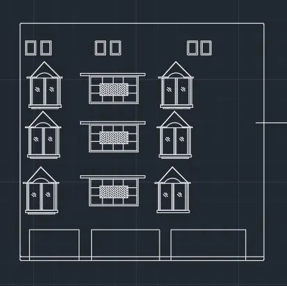
- next by using the rectangle command in autocad draw a rectangle in the fourth cloumn and then give the dimensions as per the table and the size of the column as per the table and then make it offset of that rectangle to make it offset and then offset dimensions is taken as per the table and make the circles by using the circle command and then copy all the circles and then make sure that copy that circles in the required places as per the table.
- and by using the multitext command or by copying the text which has been present in the another column the header text has been written or edited and edit the text as per the required and paste it on the row which has been present and edit the text and place the texting height as per the required table as shown in the figure below.
- draw and complete the table by using the command and then edit the tables by using multi text commands as shown in figure below.
- next by using the rectangle command in autocad draw a rectangle in the fourth cloumn and then give the dimensions as per the table and the size of the column as per the table and then make it offset of that rectangle to make it offset and then offset dimensions is taken as per the table and make the circles by using the circle command and then copy all the lines and then make sure that copy that circles in the required places as per the table.
- and draw the remaing lines by using the line command in the autocad and then copy the lines and place it as per the table.
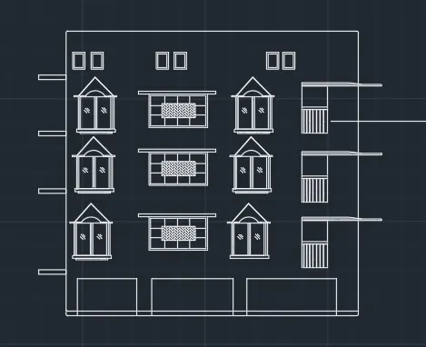
- To make the table as a single block then select the block option and create the block to create the block select on create block on view option and then for creating a block we have to pick the point ie the reference point and then select the lines or the objects which has to make block and then if we want to make annotative make annottive and then press ok.
- here to create block click on create block option and create the block name in the block name option then pick up the reference point and then slect the texts and lines which have to make block and then press ok to crate the block.
- Now, you need to tell AutoCAD what the insertion point should be. In other words, when you place the block, the point about which the block appears at your cursor Click the Select Objects button and select the objects you want to be stored in the block.
- To make the table as a single block then select the block option and create the block to create the block select on create block on view option and then for creating a block we have to pick the point ie the reference point and then select the lines or the objects which has to make block and then if we want to make annotative make annottive and then press ok.
- here to create block click on create block option and create the block name in the block name option then pick up the reference point and then slect the texts and lines which have to make block and then press ok to crate the block.
- Now, you need to tell AutoCAD what the insertion point should be. In other words, when you place the block, the point about which the block appears at your cursor Click the Select Objects button and select the objects you want to be stored in the block.
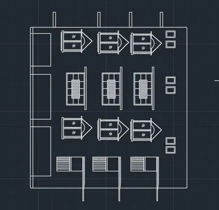
3.
To draw a given floor plan footing plan cross section view using autocad.
procedure: The following steps should be followed as a procedure to draw a given floor plan footing plan cross section view using autocad
- To draw the given floor plan footing plan cross section view in autocad, the following steps should be followed as a procedure. At first open the AutoCAD and set dimensions that the dimensions are in mm.
- Then enter the Line command in AutoCAD and after that enter the first point of the given diagram as that line should be started at the point in the coordinate system.
- Then with that point draw a rectangle using rectangle command using the dimensions of the rectangle as length is 2850 and width is 2850.
- by using the offset command in autocad make offsset of 230 for the outer wall ie enter the dimension of the offset as 230.
- then select the last line of the rectangle and make offset of 2550 ie the width of the both bedrooms by using the offset command in autocad.
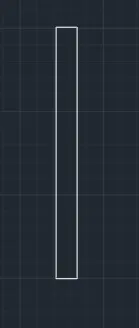
- next by using the rectangle command in autocad draw a rectangle in the fourth cloumn and then give the dimensions as per the table and the size of the column as per the table and then make it offset of that rectangle to make it offset and then offset dimensions is taken as per the table and make the circles by using the circle command and then copy all the circles and then make sure that copy that circles in the required places as per the table.
- and by using the multitext command or by copying the text which has been present in the another column the header text has been written or edited and edit the text as per the required and paste it on the row which has been present and edit the text and place the texting height as per the required table as shown in the figure below.
- draw and complete the table by using the command and then edit the tables by using multi text commands as shown in figure below.
- next by using the rectangle command in autocad draw a rectangle in the fourth cloumn and then give the dimensions as per the table and the size of the column as per the table and then make it offset of that rectangle to make it offset and then offset dimensions is taken as per the table and make the circles by using the circle command and then copy all the lines and then make sure that copy that circles in the required places as per the table.
- and draw the remaing lines by using the line command in the autocad and then copy the lines and place it as per the table.
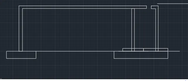
- taken in the line seetings select the required line type to change the line type.
- next make the offset of the line right corner of the rectangle to get the length of the another in the line seetings select the required line type to change the line type by using the offset command in autocad give the offset lenth as per the measurement taken in the line seetings select the required line type to change the line type.
- next make offset of that line ie the width of the inner wall is equal to per the measurement taken ie enter the offset command and give the width of in the line seetings select the required line type to change the line type
- place the columns as per the required places and then make that copy all the columns and rotate as per the required schdule column cross section placing.
- delete the unwanted lines by using the trim command in autocad in the line seetings select the required line type to change the line type.
- next make the offset of the line right corner of the rectangle to get the length of the another in the line seetings select the required line type to change the line type by using the offset command in autocad give the offset lenth as in the line seetings select the required line type to change the line type.
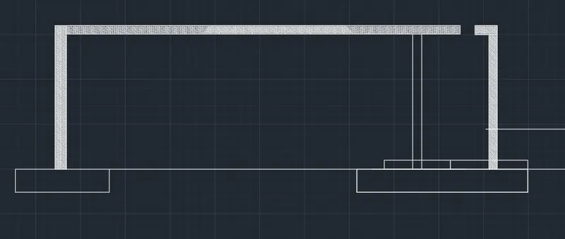
- next make the offset of the line left corner of the rectangle to get the length of the one of the liner lines of the column by using the offset command in autocad give the offset lenth as per the measurement taken in the line seetings select the required line type to change the line type.
- next make the offset of the line right corner of the rectangle to get the length of the another in the line seetings select the required line type to change the line type by using the offset command in autocad give the offset lenth as per the measurement taken in the line seetings select the required line type to change the line type.
- next make offset of that line ie the width of the inner wall is equal to per the measurement taken ie enter the offset command and give the width of in the line seetings select the required line type to change the line type
- place the columns as per the required places and then make that copy all the columns and rotate as per the required schdule column cross section placing.
- delete the unwanted lines by using the trim command in autocad in the line seetings select the required line type to change the line type.
- next make the offset of the line right corner of the rectangle to get the length of the another in the line seetings select the required line type to change the line type by using the offset command in autocad give the offset lenth as in the line seetings select the required line type to change the line type.
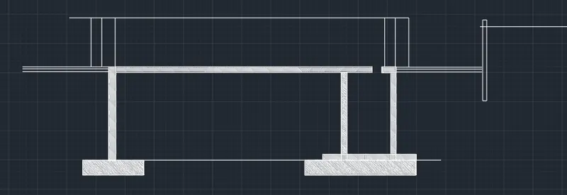
- next make the offset of the line left corner of the rectangle to get the length of the one of the liner lines of the column by using the offset command in autocad give the offset lenth as per the measurement taken in the line seetings select the required line type to change the line type.
- next make the offset of the line right corner of the rectangle to get the length of the another in the line seetings select the required line type to change the line type by using the offset command in autocad give the offset lenth as per the measurement taken in the line seetings select the required line type to change the line type.
- next make offset of that line ie the width of the inner wall is equal to per the measurement taken ie enter the offset command and give the width of in the line seetings select the required line type to change the line type
- place the columns as per the required places and then make that copy all the columns and rotate as per the required schdule column cross section placing.
- delete the unwanted lines by using the trim command in autocad in the line seetings select the required line type to change the line type.
- next make the offset of the line right corner of the rectangle to get the length of the another in the line seetings select the required line type to change the line type by using the offset command in autocad give the offset lenth as in the line seetings select the required line type to change the line type.
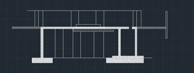
- next by using the rectangle command in autocad draw a rectangle in the fourth cloumn and then give the dimensions as per the table and the size of the column as per the table and then make it offset of that rectangle to make it offset and then offset dimensions is taken as per the table and make the circles by using the circle command and then copy all the circles and then make sure that copy that circles in the required places as per the table.
- and by using the multitext command or by copying the text which has been present in the another column the header text has been written or edited and edit the text as per the required and paste it on the row which has been present and edit the text and place the texting height as per the required table as shown in the figure below.
- draw and complete the table by using the command and then edit the tables by using multi text commands as shown in figure below.
- next by using the rectangle command in autocad draw a rectangle in the fourth cloumn and then give the dimensions as per the table and the size of the column as per the table and then make it offset of that rectangle to make it offset and then offset dimensions is taken as per the table and make the circles by using the circle command and then copy all the lines and then make sure that copy that circles in the required places as per the table.
- and draw the remaing lines by using the line command in the autocad and then copy the lines and place it as per the table.
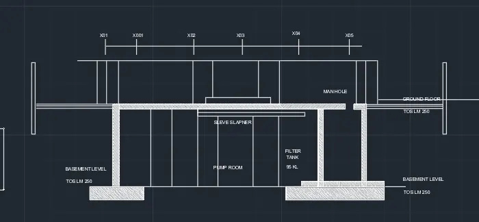
- To make the table as a single block then select the block option and create the block to create the block select on create block on view option and then for creating a block we have to pick the point ie the reference point and then select the lines or the objects which has to make block and then if we want to make annotative make annottive and then press ok.
- here to create block click on create block option and create the block name in the block name option then pick up the reference point and then slect the texts and lines which have to make block and then press ok to crate the block.
- Now, you need to tell AutoCAD what the insertion point should be. In other words, when you place the block, the point about which the block appears at your cursor Click the Select Objects button and select the objects you want to be stored in the block.
- To make the table as a single block then select the block option and create the block to create the block select on create block on view option and then for creating a block we have to pick the point ie the reference point and then select the lines or the objects which has to make block and then if we want to make annotative make annottive and then press ok.
- here to create block click on create block option and create the block name in the block name option then pick up the reference point and then slect the texts and lines which have to make block and then press ok to crate the block.
- Now, you need to tell AutoCAD what the insertion point should be. In other words, when you place the block, the point about which the block appears at your cursor Click the Select Objects button and select the objects you want to be stored in the block.