Creating Kitchen layout, Hatching of Architectural elements and sectional view of an Industrial Building in AutoCad
1.Create the layouts of the Kitchen and provide hatches pattern.
Aim: Create the layouts of the Kitchen and provide hatches pattern using lines, rectangle,hatch,blocks etc.
Size of Doors and Windows are as followed :
- Door 1 or Dl as 1000mm X 2100mm
- Door 2 or D2 as 1000mm X 2100mm
- Window 1 or WI as 900mm X 1500mm
Procedure:
Step 1:
- Open new file in AutoCAD
- Type 'un' in command box and press enter.
- Change unit type to decimal and precision to 0.00 and insertion scale to millimeters.
- Type LIMITS in the commant prompt.
- set left end corner coordinates as 0,0 and right end corner as 10000,10000.
- press enter.
Step 2 :-
- Type "LA" in the command box and press enter.
- Open layer properties and create new layers by clicking on new layer icon.
- Assign required layes as walls,doors and windows,fittings,text and dimensions.
Step 3:-
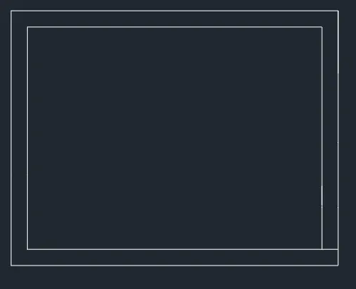
- In the command prompt type rec.
- dimensions are 4734 x 3688 mm.
- In the command prompt type offset
- offset it to the distance of 250mm.
- Type "Explode" in command box and press enter and explode both rectangles.
STEP 4 :-
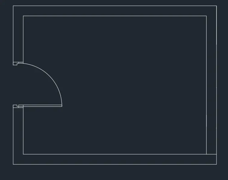
- Create door opening using Line and Trim command.
- Type "O" for offset and press enter.
- Specify offset distance as 600 and press enter.
- Select the bottom edge of inner rectangle and click on the top.
- Type "O" for offset and press enter.
- Specify offset distance as 40 and press enter.
- Select the last offsetted line and click on the top.
- Type "O" for offset and press enter.
- Specify offset distance as 35 and press enter.
- Select the line drawn earlier and click on right.
- Type "O" for offset and press enter.
- Specify offset distance as 900 and press enter.
- Select the last offset line and click on right.
- Type "O" for offset and press enter.
- Specify offset distance as 450 and press enter.
- Select the last offset line and click on right.
- Type "O" for offset and press enter.
- Specify offset distance as 900 and press enter.
- Select the last offset line and click on right.
- Type "O" for offset and press enter.
- Specify offset distance as 450 and press enter.
- Select the last offset line and click on right.
- Type "O" for offset and press enter.
- Specify offset distance as 900 and press enter.
- Select the last offset line and click on right.
- Type "O" for offset and press enter.
- Specify offset distance as 450 and press enter.
- Select the last offset line and click on right.
- Select the last offset line and click on right.
- Select the last offset line and click on right.
- Type "O" for offset and press enter.
- Specify offset distance as 630 and press enter.
- Select the last offset line and click on right.
- Type "O" for offset and press enter.
- Specify offset distance as 10 and press enter.
- Select the bottom edge of inner rectangle and click on top.
- Type "O" for offset and press enter.
- Specify offset distance as 20 and press enter.
- Select the line offset at 35 from left and click on right.
- Repeat the same procedure for all offset lines drawn above with the given offset distance.
- Create hob using rectangle and circle commands.
STEP 5
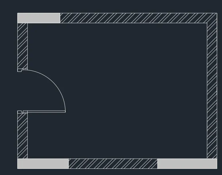
- In the command prompt type hatch to hatch the model.
 ]
]
STEP 6:
- Draw the fridge as shown in the question figure and convert it as block.
- Type "l" for insert command and press enter and insert the fridge block and place at the required space in the plan.
- Type "l" for insert command and press enter and insert the Dl block and place at the required space in the plan.
- Similarly create the windows and convert it as blocks and save them with different names.
- Type "l" for insert command and press enter and insert the window blocks and place at the required space in the plan.
- In the command prompt type rec > dimensions, to do the fridge.
- In the command prompt type offset and offset it to the desired distance to get the Micro Oven .
- In the command prompt type trim to trim the extras.
- In the command prompt type offset and offset it to the horizontal distance of 350,450,900,450,450 and 560 .
- In the command prompt type offset and offset it to the vertical distance of 600.
- In the command prompt type trim to trim the extras .
- In the command prompt type line type and load the dotted lines.
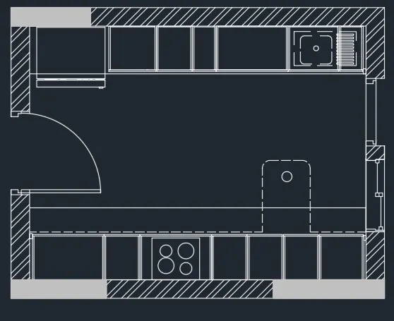
Step 7:
- In the command prompt type text to text the given annotations.
- In the command prompt type dimensions to given the dimensions to your plan
- In the command prompt even the leader command is used to name the dimensions .
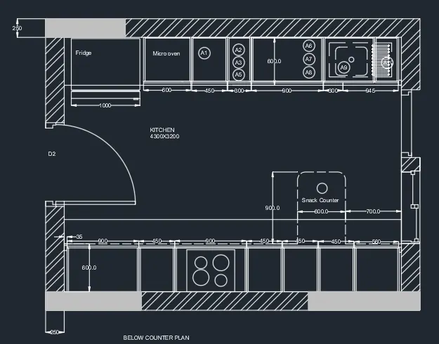
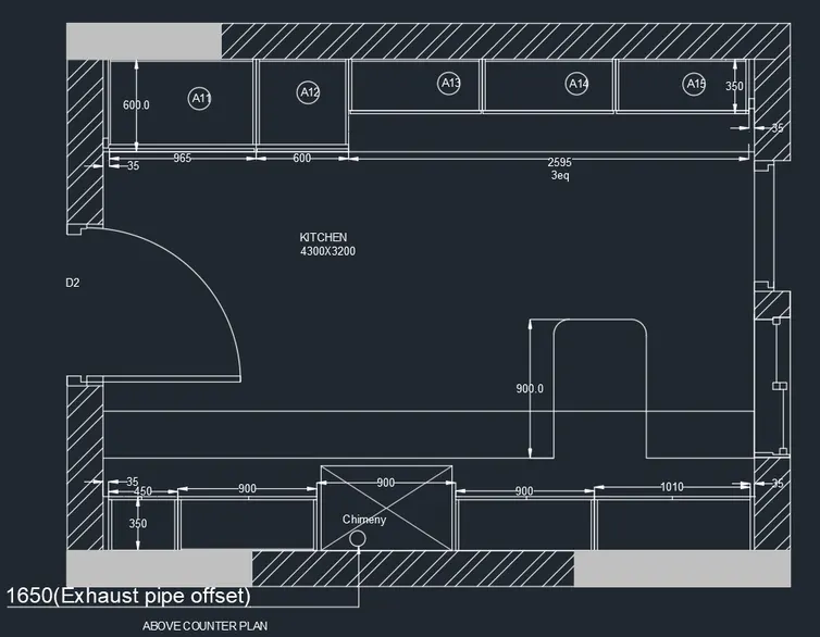
STEP 8:
- Place all the elements in the corresponding layers.
Result
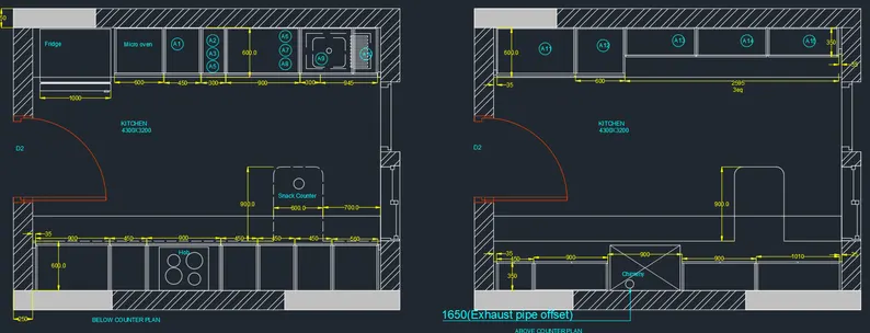
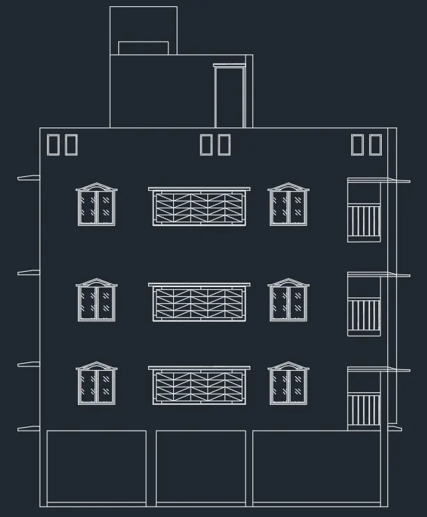
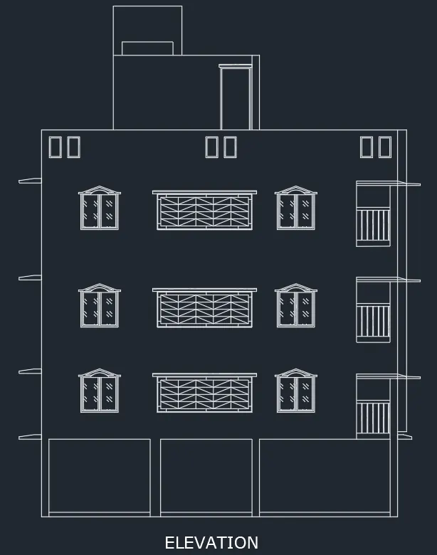
2.To Create the elevation of the plan and apply proper hatch in the walls, doors,windows, and other architectural elements.
AIM: To Create the elevation of the plan and apply proper hatch in the walls, doors,windows, and other architectural elements.
Procedure:
Step 1:
- Open the file Challenge 7 in AutoCAD
- Type 'un' in command box and press enter.
- Change unit type to decimal and precision to 0 and insertion scale to millimeters.
- Type LIMITS in the commant prompt.
- set left end corner coordinates as 0,0 and right end corner as 10000,10000.
- press enter.
Step 2:
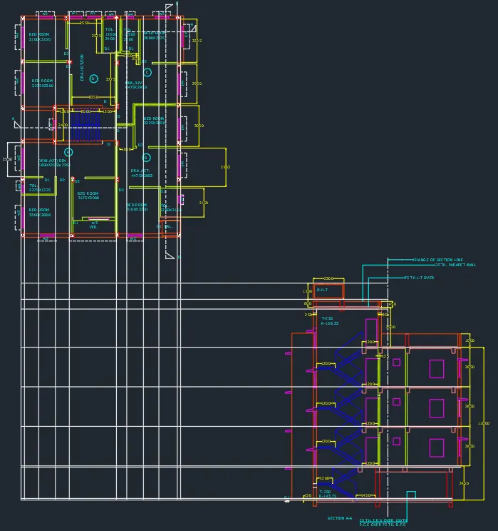
- In the command promt enter XL'
- select Vertical lines.Draw the Projection lines from the given plan.
- In the command promt enter XL' and select select horizontal lines.
- Draw the Projection lines from the given section.
 s
s
STEP 3
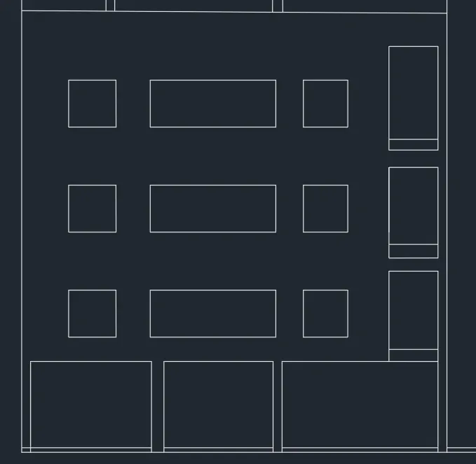
- type TR in the command prompt.
- Trim off the unwanted lines.
Step 3:
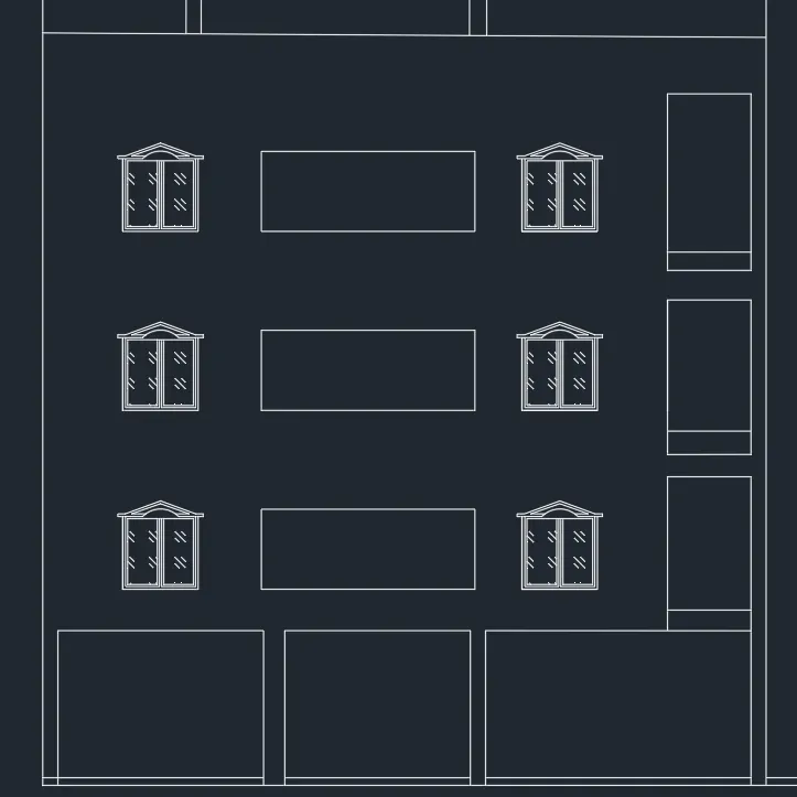
- Create a window of 1000mm X 1200mm.Create a rectangle of 1000mm X1100mm and dive the rectangle into two parts.
- Offset the centre line with 100mm distance on both sides. Take that as one side of the rectangle draw a rectangle of 900mm X900mm and
- again offset the retangle 100mm inside .Do the same on the other half.
- By using Using Arc crate an arc and by using line create inclined portion @30 degress on the both sides.Hatch the window doors with th Ghost
- glass hatch and scale it to the required size.
- Make that window as block and insert the window in the required places.
Step 4:(Drawing Varandah)
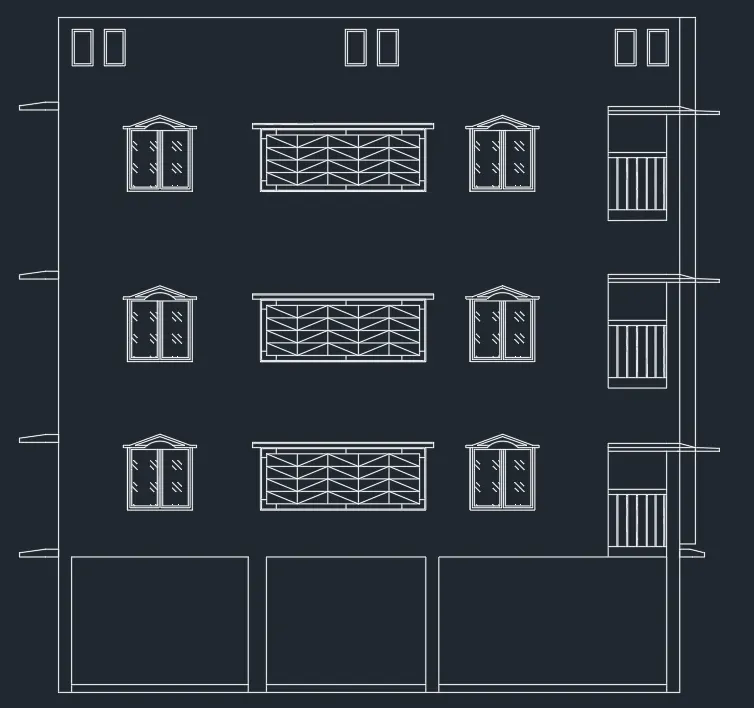
- By using join command join all the lines and offset the rectangle of 300mm and divide the rectangle horizontally into 4 parts and vertically into five parts.
- Join the the lines to obtain the required pattern.Make it as block and place it in the above two floors.
- Drawing of Balcony:
- Divide the bottom line of bolcony into six parts and draw the lines and projects the lines @ 600 mm upwards.
- Provide the sun shade at the edge of the wall on the both sides.Copy it in the above floors.
Step 5:(Drawing of Over head tank)
- Off set the floor line to the distance of 2500mm 600mm and 1200mm and project the lines from the plan and columns from bottom and
- trim the unwanted lines.
- Provide a door of 1000mm X 2100mm at the right corner.
STEP 6
- Type MTEXT for typing texts in the drawing.
RESULT
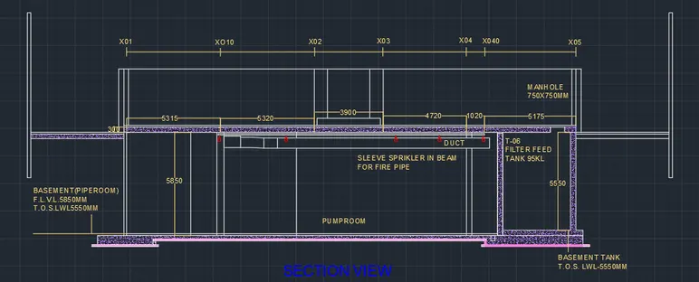
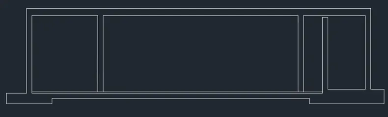
3.Section view of industrial bulding.
Aim: To Create the section view of an industrial building, to provide appropriate hatches and dimensions wherever required and also, provide annotations to the drawing.
Procedure:
Step 1:
- Open new file in AutoCAD
- Type 'un' in command box and press enter.
- Change unit type to decimal and precision to 0.00 and insertion scale to millimeters.
- Type LIMITS in the commant prompt.
- set left end corner coordinates as 0,0 and right end corner as 10000,10000.
- press enter.
Step 2:
- In the command prompt enter line and draw a line of length 28200mm and offset the line 400mm,top the top two times.
- By using line command join all the lines and trim off the unwanted lines.
- Draw a line of 6400mm vertically up wards from the end of above offset line.
- Offset the line @1700,5315,5320,3900,4720,1020,5025mm.
- Offset the the Above offseted lines by 200mm on the both sides.
- Connect all the vertical lines by line command horizontally.
- Offset the horizontal line @500mm down wards.
- Trim the all unwanted lines.
Step 3:
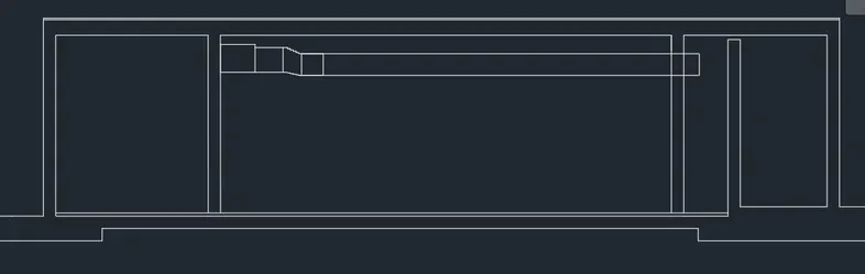
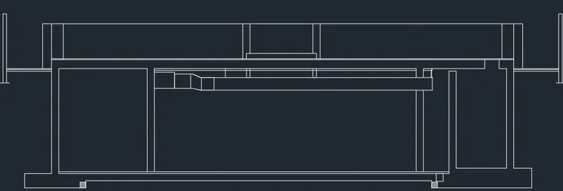
- Provide duct of pipe of 15450mm X 700mm Between the middle Two columns.
- Draw a rectangle of 1100mm X 900 mm at the second left column and draw another rectangle of 900mm X 800mm.
- Draw an anotherrectangle of 700mm X 700mm at a distance of 600mm from second rectangle.
- Connect the two triangles by using line command in the steps manner as thread as 90mm and riser as 20mm.
Step 4:
- Offset the above line @2500mm vertically up wards and project the corner columns .
- offset the line @5320mm from the second leftcolumn.
- Again offset the line@400mm,3500mm and 400mm.
- Trim of the unwanted lines-offset the line between middle two columns at a distance of 300 mm up wards. Project the middle columns downwards to the duct pipe.
- Offset the left column line @500mm.2500mm,2700mm to-wards left side.
- Extend the line from column to the ofseted line.
- Offset theextended line @50mm ,100mm to down wards.
- Trim off the unwanted lines.By using mirror commnad mirror the same in the other side.
- Create a man hole of 700 X 500mm at the right corner column.
STEP 5
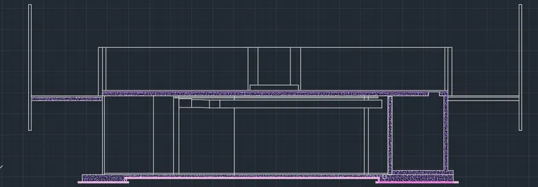
- Type hatch in the command prompt.
- select the hatch pattern for concrete.
- Bring the cursor inside the section and click inside the walls.
Step 6:
- By using dimension style command change text , text height is 400mm and arrown size as 200mm.Give all the diamnesions.
- By using multiline text write the text.
- By using the multileader command provide multileaders whereever required and write the text.
RESULT