Creating Kitchen layout, Hatching of Architectural elements and sectional view of an Industrial Building in AutoCad
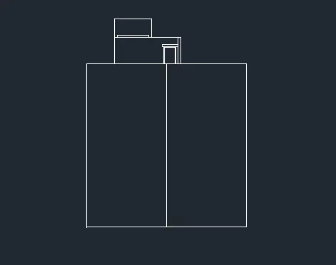
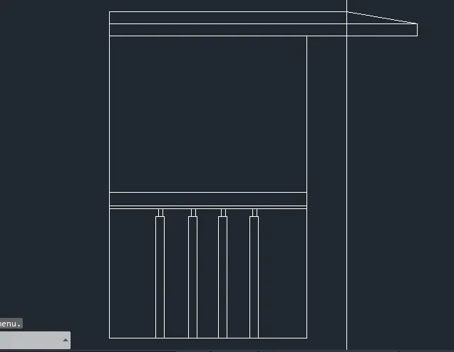
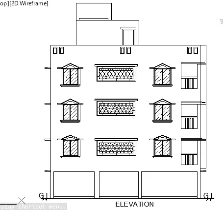
AIM:CREATION OF ELEVATION FROM CHALLENGE 7 ALONG WITH HATCHES FOR WINDOWS,WALLS ETC.
INTRODUCTION:
Hatch in AutoCAD is used to fill patterns inside an enclosed area. The patterns are hatched, gradient, and solid fill.
- The gradient patterns are defined as a smooth transition between two colors.
- Solid is single colour used to define solid blocks like wall.
- pattern holds of varies types based on its application like brick for wall,glazing for glasses etc.
PROCEDURE:
- create a rectangle and draw a center vertical line.
- create parapet potion using lines/polyline command.
- create the window frame using lines,rectangle,offset command and arc.
- create balcony opening with rails and attachtment of sunshade using rectangle and line command.
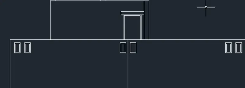
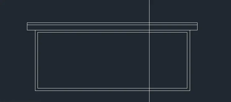
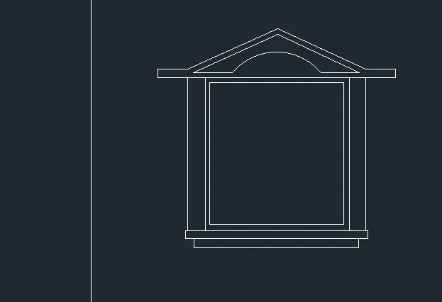
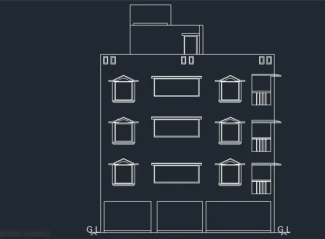
- for hatches of window,use ANSI136 for glazing.
- for net of window,use NET3 with scale factor
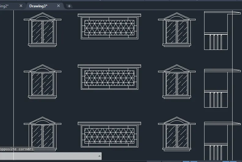
RESULT:
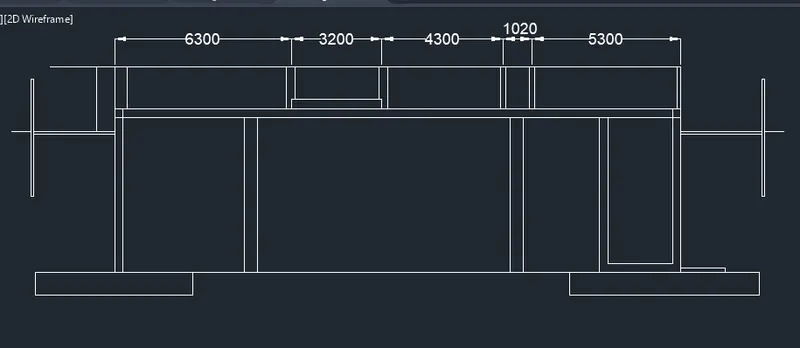
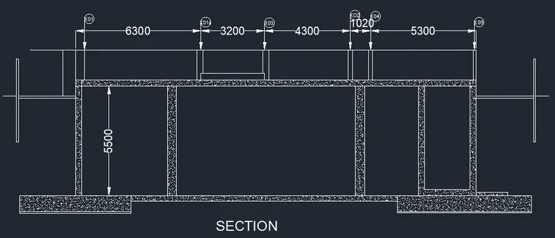
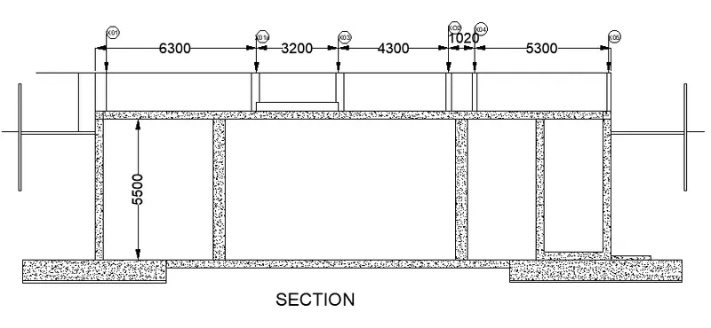
AIM: Create the section view of an industrial building
PROCEDURE:
- draw the given section of a building assume the dimensionn.
- take wall thickness as 300 and partition wall 150.
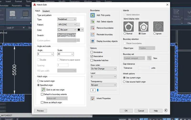
for hatching:
- type H for hatch command.
- select pattern as AR-CONC.
- select the area to be hatched-enter.
- select hatch-option for hatch edit,set the scale factor and see preview.
- if hatch is visible, set ok.
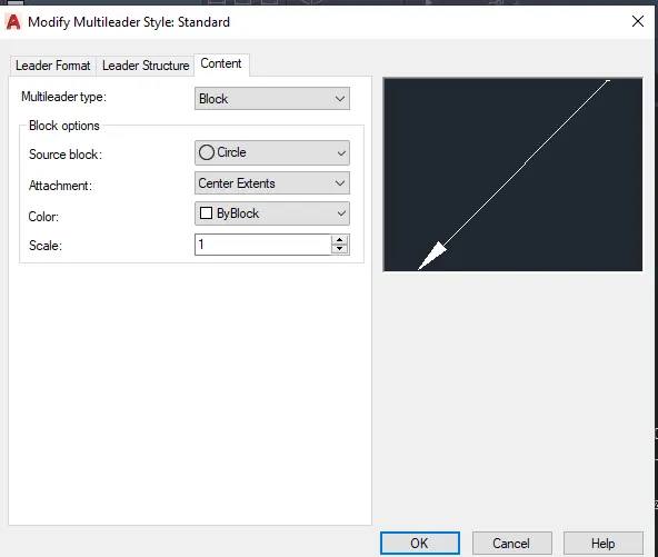
for marking labels:
- select MLEADER- setting.
- in content select multileader type as block.
- specify soruce block as circle.
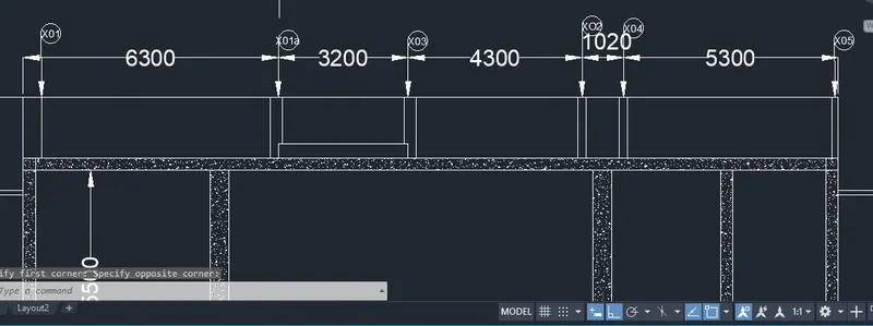
RESULT:
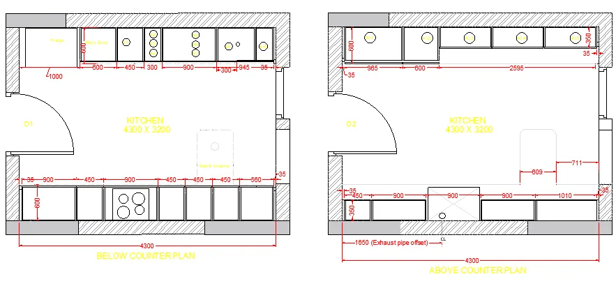
AIM:Create the layouts of the Kitchen and provide hatches pattern
PROCEDURE:
- create a rectangle of dimensions 4300x3200.
- offset 230 otwards to create the walls.
- for making of door,draw a horizontal line an doffset 500 o each sides.
- now trim thr potion and use line and arc command to make door.
- select hatch with pattern ANSI43 and provide scale factor 20.
- select the portion to be made colour and use hatch-solid.
- enter B for block comand, name it as DOOR and select the D1 and click ok.
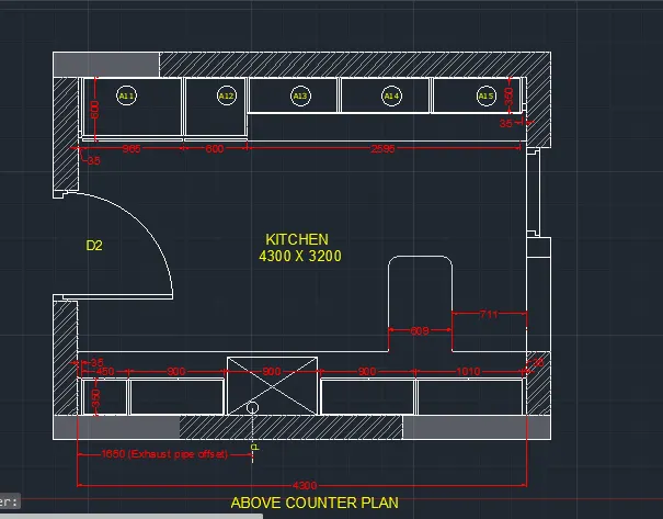
- insert the door for D2 in counter plan.
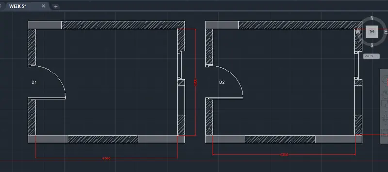
- for making snack counter,offset bottom horizontal line with 600 and 1500.
- offset right veritcal at distance 700 and 1300.
- for bottom slab portion in 1st plan, make a rectangle of 900x650,450x600 and 560x600.
- place rectangles in order by selecting corner point as base point.
- now offset interior sides with distance of 20 in all boxes.
- for upper slab prtio also follow similar way of making rectangle,placing and offset.
- use text command with certain height to enter names and create a annotation with A1,A2 so on for boxes name.
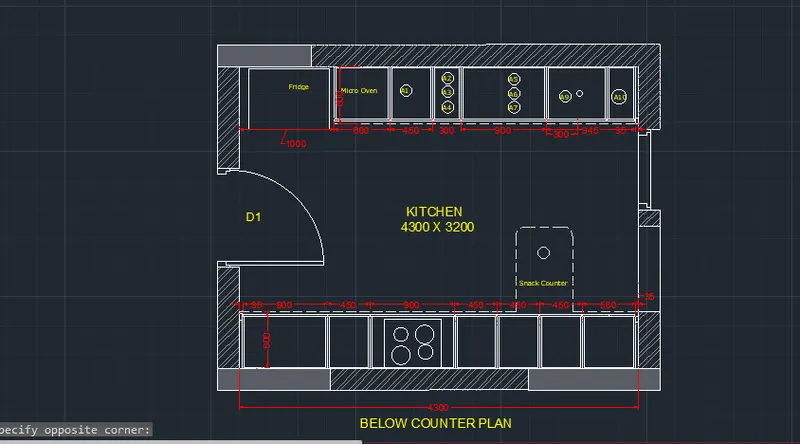
- similarly procedure for snack counter and slab making as mentioned above for next plan also.
RESULT: