Creating Kitchen layout, Hatching of Architectural elements and sectional view of an Industrial Building in AutoCad
AIM:
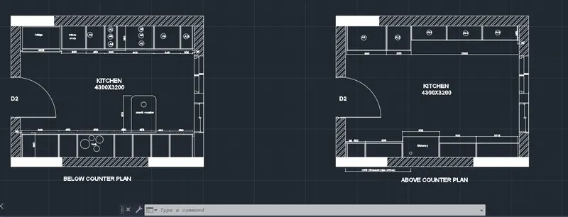
To create the layout of the kitchen and providing hatches to it using the autocad in detail.
PROCEDURE:
STEP:-1
- Below counter plan.
- First we have to draw the line horizontally with the length of 4300mm.
- Next draw another line from the previous line with the length of 3200mm
- Next again we draw the line from previous line with the length of 4300 mm horizontally backwards at the top. Next we have to join the first line and the last line which we have drawn previously.
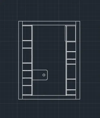
- Next offset the four sides with the offset of 20mm outside. Next we have to offset the line inside with the offset command with the length of 600mm, including the fridge.
- Afterwards we draw the fridge separately with other dimensions in the kitchen layout.
- Next we need to draw the line opposite side to create the parts of kitchen.
- Next divide the seven parts downside with different dimensions compared to the upper side portion. Next leave the space left and right corners with the length of 35mm at the top and bottom.
- Next put the dimensions for the every part in the diagram.
- Next indicate the door as D2.
- Next we have use the single text command and indicate the parts where ever it requires with single text command.
- And put the dimensions for the every part in the diagram.
- Next draw the snack counter with the length of 600mm and width of 900mm. And draw the create the hub in the middle at the bottom of the kitchen.
- And create the windows using the line command and trim command, which is shown in the below figure
RESULT-
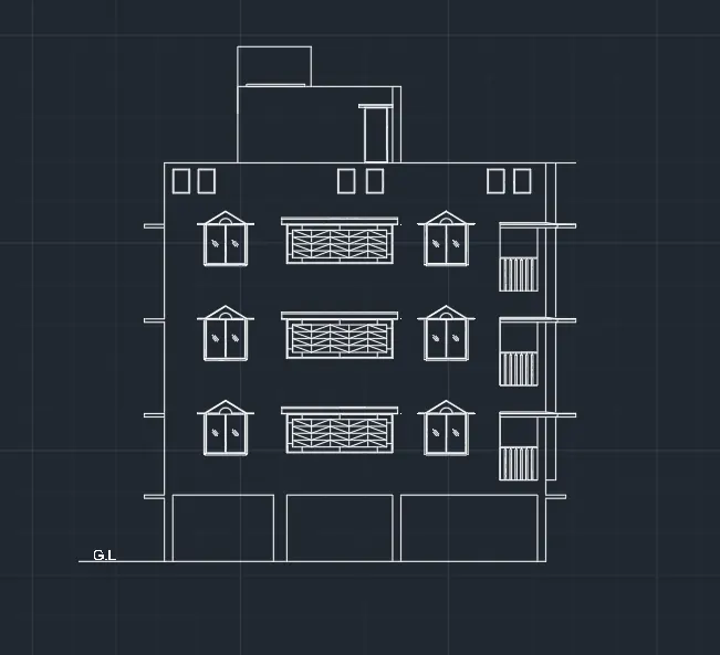
AIM- 2. Create the elevation of the plan created in the Challenges 7 and apply proper hatch in the walls, doors, windows, and other architectural elements. Refer to the dimensions in Plans and sections in Challenges 7.
- First we have to open the autocad and set the limits.
- Next we use the zoom command and press enter.
- Comming to the drawing the elevation of the residential buiding first we draw the horizontal line using the line command with the length of 11574mm.
- Next we need to draw the another line from the previous line vertically with the length of 1200mm
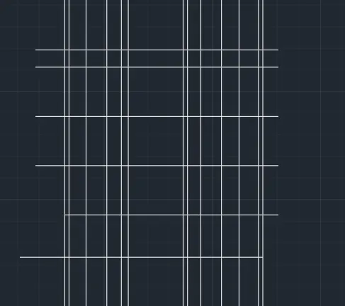
- Next we have to draw the line horizontally bawards from previous line with the length of 12150mm at the top.
- Next we draw the line downwards vertically with the length of 12000mm by drawing the last line the rectangle will be formed.
- Next we draw the rectangle at the top of the building.
- And again we draw the another rectangle on the previous rectangle with the lengths given in the given drawing
- Next we draw the three rectangles at the bottom of the rectangle with the different dimensions.
- Next we need to draw the sunshades provided in the drawing
- Next we draw the windows with standard construction dimensions with the help of line command and are command.
- Next draw the balcony part using the line command, offset command and trim command
- Next we need to draw the sunshades provided in the drawing
- Next we draw the windows with standard construction dimensions with the help of line command and are command.
- Next draw the balcony part using the line command, offset command and trim command
RESULT-
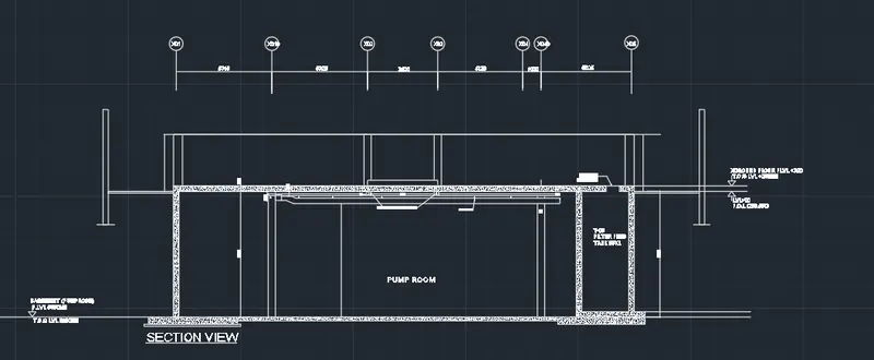
AIM-3. Create the section view of an industrial building as shown in Figure. Provide appropriate hatches and dimensions wherever required. Also, provide annotations to the drawing.
STEP:-1
- First we have to draw the X-line at anoy point on the screen.
- Next offset the line to top to a distance of 5850mm and we have to do offset of last offset line to the distance of 300mm to the top.
- Next we have to draw the vertical X-line on any point on the horizontal line.
- Next do offset of line to right to a distance of 10635mm
- Next offset the last line with a distance of 3900mm to the right.
- Next offset the Ist line with the distance of 5740mm to the right side.
- Next we do the offset for last line with the distance of 5025 to the right side.
- Offset the left and right edges with the distance of 500mm.
- Next we have to trim the outer edges using the trim command
- Next offset the bottom edge of the top floor to a distance of 30mm
- Next offset the last line with a distance of 70mm to the bottorn.
- Next offset the last line with the distance of 100mm to the bottom.
- Next we draw the splinkler pipe along with the duct pipe.
- The duct pipe thickness is 300mm and the thickness of splinkler pipe is 100mm.
- Next we draw the manhole cover with the thickness of 750mm at the right top edge of filter feed walls as shown in the figure.
- Next we draw the thickness of pump room slab with the different layers using the line command.
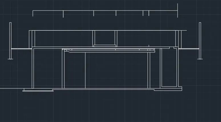
- Next we need to draw the circle with radious of 500mm, and enter the text in the circle as given in the figure.
- Next we need to use the single text command to enter the text where ever required in the section view of industrial drawing, Finally we use the hatch command to hatch the walls and floor slabs as drawn in the below figure.
- Finally we have use the dimlinear command to put the dimensions whereever required in the drawing.
RESULT-