Creating Kitchen layout, Hatching of Architectural elements and sectional view of an Industrial Building in AutoCad
Challenge 10: Creating the kitchen layout, hatching of architectural elements and sectional view of an industrial building using the AutoCAD software.
- Creating the kitchen layout.
Aim – To draw the kitchen layout using the AutoCAD software
Procedure:
- First create a new AutoCAD file using the metric units
- Type the command units and set it to the decimal units and set it to millimetres
- Type the command dimstyle and in the primary unit set it to mm and precision to 0
- Set the limits by using the limits command and specify the end points
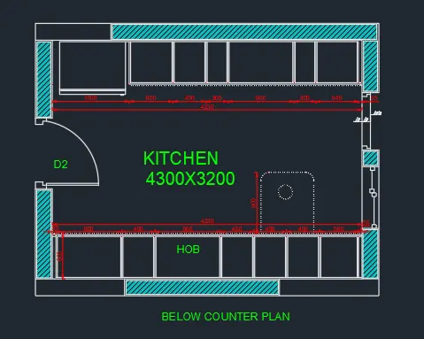
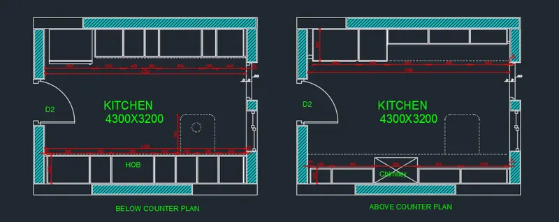
- Making the below counter plan
- Type the rectangle command REC and give the dimension, length= 4690 mm and width = 3720 mm
- Give the offset of 230 mm from all the sides in the inner portion
- Trim off the required lines using the TRIM command
- From the upper side give the offset of 20 mm in –y direction
- Again give the offset of 720 mm in the same direction
- From the left side give the offset of 35 mm in +x direction
- Again give the offset of 1000 mm in the same direction
- Trim off the required lines using the TRIM command
- Fridge is shown after trimming the lines.
- Now from the upper horizontal line give the offset of 580 mm in –y direction
- From this line give the offset of 20 mm in +y direction
- From the last vertical line (fridge) give the offset of 50 mm in the + x direction
- Now again give the offset of 20 mm in the same direction
- Trim off the required lines using the TRIM command
- From the last vertical line give the offset of 580 mm in the + x direction
- Again give the offset of 450 mm in the same direction
- Again give the offset of 300 mm in the same direction
- Again give the offset of 900 mm in the same direction
- Again give the offset of 300 mm in the same direction
- Again give the offset of 945 mm in the same direction
- Now from the middle give the offset of 10 mm on both the sides and the from the right corner shelf line give the offset of 20 mm
- Repeat the same process for the lower portion as only the dimensions are different
- Make the ISO DASH lines using the layer properties
- Make the ISO DASH line at the distance of 10 mm from the horizontal lines in both upward and downward sides
- For making the snack counter use the LINE command and give the vertical length as 900 mm and the horizontal lines as 750 mm
- Use the FILLET command for making the round corners by clicking on the radius and giving the specified radius
- Select the point and use the circle command and give the radius as 95 mm
- Use the TRIM command for making the door space
- Use the “start end direction” option from the arc as shown in the ribbon to get the curved shape of the door
- Use the rectangle and line command for making the window
- Use the hatch command and make the close boundary for doing the hatching
- Use the single line command for writing the text and do the dimensioning
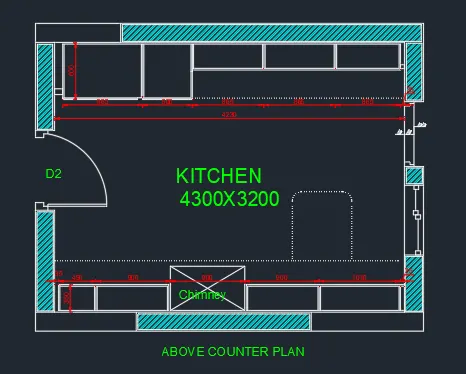
- Making the above counter plan
- Type the rectangle command REC and give the dimension, length= 4690 mm and width = 3720 mm
- Give the offset of 230 mm from all the sides in the inner portion
- Trim off the required lines using the TRIM command
- From the upper side give the offset of 20 mm in –y direction
- Again give the offset of 720 mm in the same direction
- From the left side give the offset of 35 mm in +x direction
- Again give the offset of 1000 mm in the same direction
- Trim off the required lines using the TRIM command
- Fridge is shown after trimming the lines.
- Now from the upper horizontal line give the offset of 580 mm in –y direction
- From this line give the offset of 20 mm in +y direction
- From the last vertical line (fridge) give the offset of 50 mm in the + x direction
- Now again give the offset of 20 mm in the same direction
- Trim off the required lines using the TRIM command
- From the last vertical line give the offset of 580 mm in the + x direction
- Again give the offset of 450 mm in the same direction
- Again give the offset of 300 mm in the same direction
- Again give the offset of 900 mm in the same direction
- Again give the offset of 300 mm in the same direction
- Again give the offset of 945 mm in the same direction
- Now from the middle give the offset of 10 mm on both the sides and the from the right corner shelf line give the offset of 20 mm
- Repeat the same process for the lower portion as only the dimensions are different
- Make the ISO DASH lines using the layer properties
- Make the ISO DASH line at the distance of 10 mm from the horizontal lines in both upward and downward sides
- For making the snack counter use the LINE command and give the vertical length as 900 mm and the horizontal lines as 750 mm
- Use the FILLET command for making the round corners by clicking on the radius and giving the specified radius
- Select the point and use the circle command and give the radius as 95 mm
- Use the TRIM command for making the door space
- Use the “start end direction” option from the arc as shown in the ribbon to get the curved shape of the door
- Use the rectangle and line command for making the window
- Use the hatch command and make the close boundary for doing the hatching
- The required geometry is made as per given
RESULT: Required kitchen layout is drawn as per given.
- Hatching of architectural elements
Aim- To draw the required architectural elements and do the required Hatching.
Procedure:
- First create a new AutoCAD file using the metric units
- Type the command units and set it to the decimal units and set it to millimetres
- Type the command dimstyle and in the primary unit set it to mm and precision to 0
- Set the limits by using the limits command and specify the end points
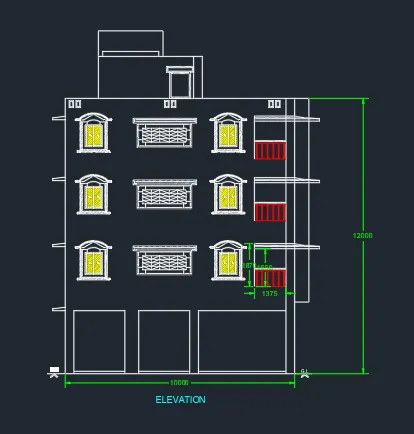
- Type the REC command and give the dimensions as length = 10000mm and width 12000 mm
- Now from seeing the PLAN type the Xline command and give the vertical projections from the Plan
- The required vertical lines are drawn in elevation which give the boundaries of windows and lintel
- Make the windows with the help of vertical projections.
- Using the ARC command select the start end direction and make the curved portion of the window
- Make the left over part with the help of line command
- Do the required hatching as shown using the Hatch command
- From the lower horizontal line give the offset of 108 mm in +y direction
- Trim off the required line b/w the vertical lines projections
- Now from the upper part for getting two rectangles of same length and 1 length rectangle
- From the upper horizontal line of inside bigger rectangle give the offset of 1051 mm in +y direction for getting balcony lower horizontal boundary.
- Trim off the unwanted line
- Now from this lower boundary line again give the offset of 1650 mm in the +y direction
- Now again give the offset of 220 mm in the same direction for getting balcony chajja
- Make the balcony part with the help of line command
- Make the middle portion with the help of REC command and offset command
- Now copy these parts and paste it on the upper sides for getting the two more floors
- Make the overhead tank room and walls with the help of LINE Command, Rectangle command and offset command
- Use the single line text for giving information as per given
- Do the dimensioning with the help of DIMLINEAR Command
- Use the layer properties for assigning different colours to different parts
- Do the hatching with the help of hatch command as per given.
RESULT: The Architectural geometry is made as per given.
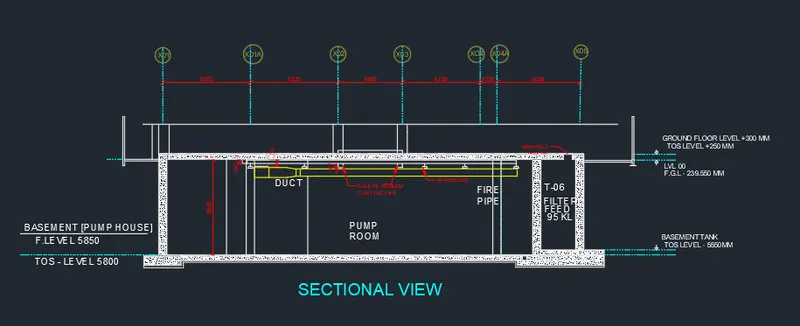
- Sectional view of industrial building(Pump house )
Aim- To draw a sectional view of the pump house using the AutoCAD sofware.
Procedure:
- First create a new AutoCAD file using the metric units
- Type the command units and set it to the decimal units and set it to millimetres
- Type the command dimstyle and in the primary unit set it to mm and precision to 0
- Set the limits by using the limits command and specify the end points
- Type the REC command and give the dimensions as length = 25800 mm and width = 6450 mm
- Type the explode command and explode the rectangle
- From the horizontal lines of the rectangle give the offset of 300 mm in the inner sides
- From the vertical lines of the rectangle give the offset of 500 mm in the inner sides
- Now from the middle of the vertical columns give the offset of 5320 mm in the +x direction
- Again give the offset of 3900 mm in the same direction
- Again give the offset of 4720 mm in the same direction
- Again give the offset of 1020mm in the same direction
- Again give the offset of 5025 mm in the same direction
- Make the lines as a dotted grid lines with the help of the layer properties and choosing the ISO DASH Lines
- From the center lines give the required offset of 250 mm in the both sides for getting columns as reference
- Now give the required offsets from the horizontal lines of the offset for getting upper portion of duct and sleeves in the beam
- Trim off the required lines for getting the required geometry
- Make the Duct and Sprinkler with the help of Line command as per given in the geometry
- Use the single line text of required height (say 320 mm taken) and angle 0 degree and give the information as stated
- Use the layer properties for assigning different columns to different parts
- Do the required dimensioning with the help of DIMLINEAR command
- Type the HATCH command and do the required hatching as shown and choosing the AR-CONC style
RESULT: Required Pump House geometry is made as per given.