Creating Kitchen layout, Hatching of Architectural elements and sectional view of an Industrial Building in AutoCad
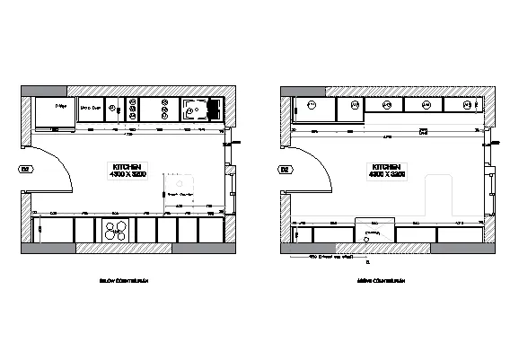
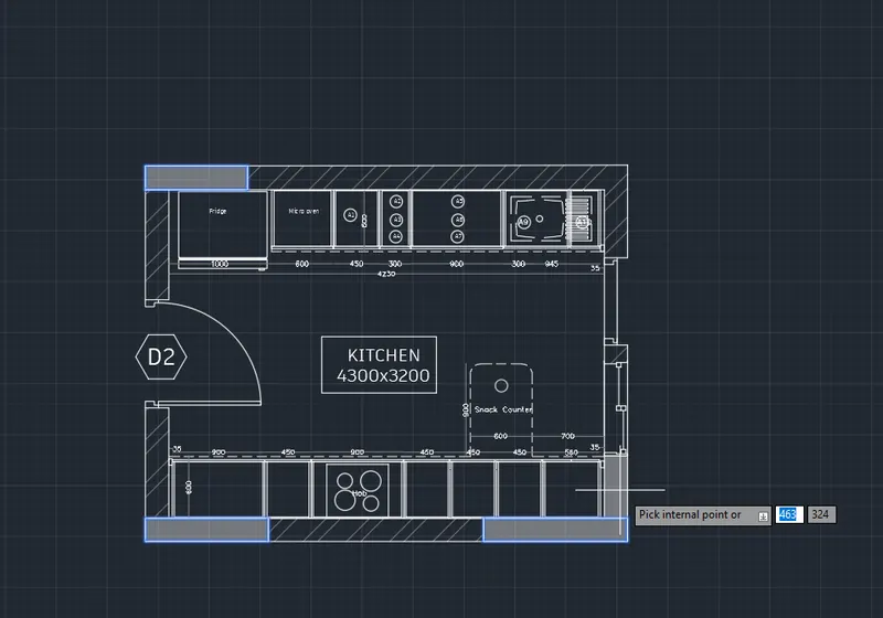
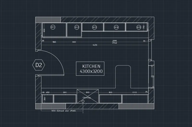
Create the layouts of the Kitchen and provide hatches pattern as shown. Also, use blocks wherever required. Provide appropriate dimensions in the plan. Assume the size of doors, appliances and others as per the standards.
Aim:
To create layouts of the kitchen and provide hatches as shown. Use blocks and also provide dimensions to the plan.
Commands used:
Line
Polygon
Rectangle
Circle
Erase
Copy
Trim
Mirror
Offset
Extend
Array
Move
Rotate
Dimension
Text
Fillet
- Draw the layout of the kitchen using the line command and draw the kitchen utilities using the required tools
- Add in the hatch using the hatch command in the required places
- Trim and extend the lines where needed.
- Use the fillet command to draw the snack counter.
- Add text to the required places using a multi-line command or a single-line text command.
- Add in dimensions using the command dimlinear.
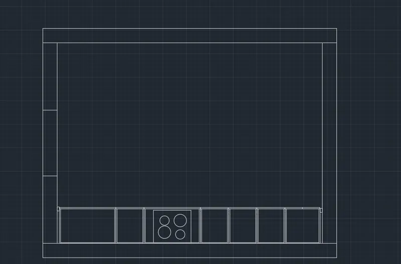
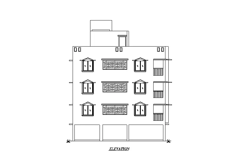
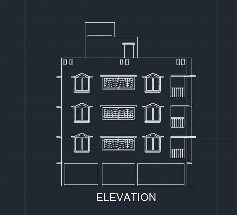
2. Create the elevation of the plan created in the Challenges 7 and apply proper hatch in the walls, doors, windows, and other architectural elements. Refer to the dimensions in Plans and sections in Challenges 7.
Aim:
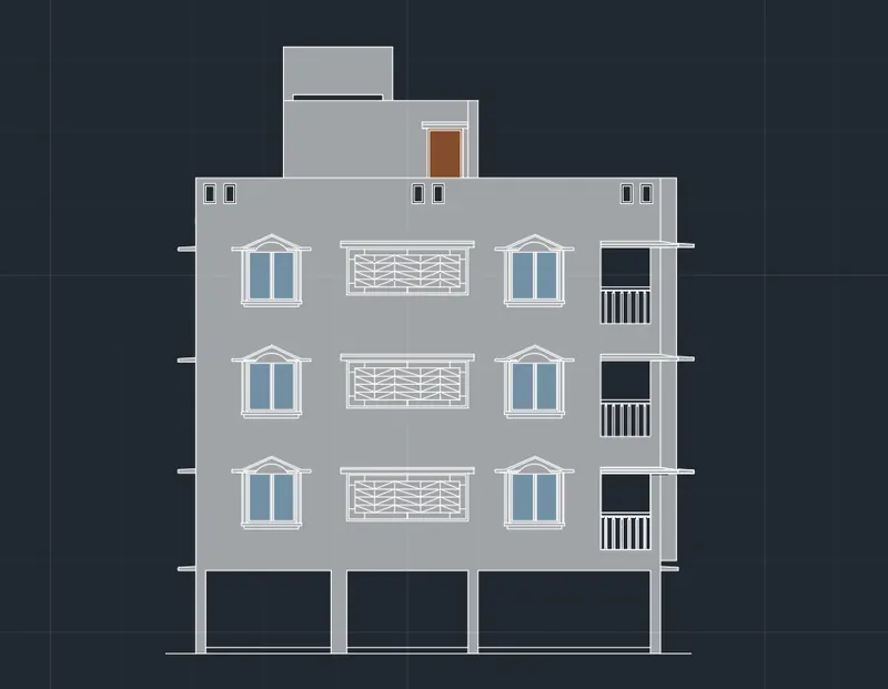
To create the elevation of the plan created in challenge 7 and provide hatches to the walls, doors, windows, and other architectural elements.
Commands used:
Line
Polygon
Rectangle
Circle
Erase
Copy
Trim
Mirror
Offset
Extend
Array
Move
Rotate
Dimension
Text
Fillet
Procedure:
- First, draw the outline for the elevation using the line command.
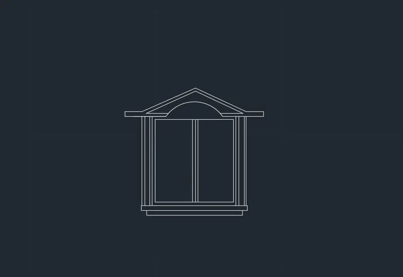
- Draw the windows separately and copy and paste the required positions
- Using the array command draw the railings.
- For drawing the elections refer to the drawing from Challenge 7.
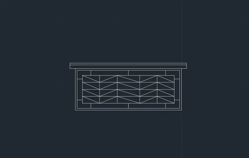
Type in the text needed.
Using the hatch command and the transparency as 40 add the hatch to the windows door and wall.
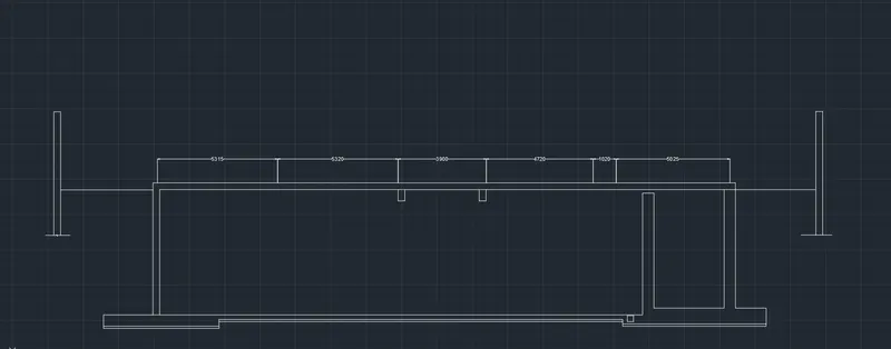
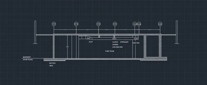
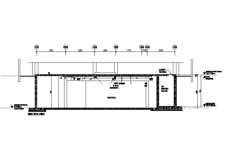
3. Create the section view of an industrial building as shown in Figure. Provide appropriate hatches and dimensions wherever required. Also, provide annotations to the drawing.
Aim:
To create the section view of an industrial building as shown in the figure and Provide hatches and dimensions to the drawing.
Commands used:
Line
Rectangle
Circle
Erase
Copy
Trim
Mirror
Offset
Extend
Move
Rotate
Dimension
Text
Fillet
Procedure:
- Create horizontal and vertical construction lines.
- Offset the horizontal construction line at a distance of 5850mm and 6150mm.
- Create a line at the right top corner and offset it at a distance of 400mm.
- Offset the last offset line at a distance of 5315mm, 5320mm, 3900mm, 4720mm, 1020mm and 5025mm.
- Offset the created lines at a distance of 400mm on both the right and left sides.
- Offset the left sideline at a distance of 600mm and 2500mm and at a distance of 600mm. The filter feed is created.
- create a pump room by offsetting the filter feed wall line at a distance of 9500mm.
- Create the footings by using rectangle and explode tools.
- Create the sprinkler pipeline and the sprinkler at a distance of 25mm from the bottom of the slab.
- Create the text using the single-line text command.
- Create the dimensions using the command dimlinear.