Creating Kitchen layout, Hatching of Architectural elements and sectional view of an Industrial Building in AutoCad
1):
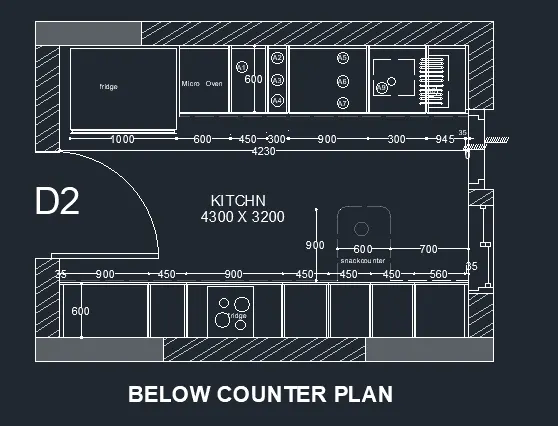
Aim: To Create the layouts of the Kitchen and provide hatches pattern
Introduction: To Create the layouts of the Kitchen and provide hatches pattern. By using AutoCad
Procedure:
Step1:
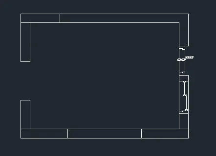
- Draw a rectangle by typing the command “REC” in command box
- Select the first point give the dimension 4300x3200
- Next take the offset command make an offset of 230mm in the outer section
- For the window take the size of windows and make the offset from the external line the wall and trim the extra lines
Step2:
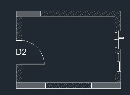
- Creation of door and hatches
- For the door take the shortcut key ctrl+3 adjust size of the door as per required take command move and place it at the position
- For the hatches take command hatch select the patten place it in the close boundary adjust the hatch size, angle, and transparency as need
Step3:
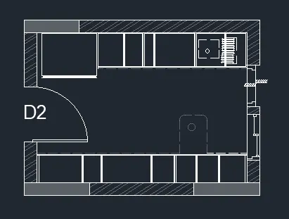
- now take the line command check the dimensions from the refrance drawing draw the given materials or kitchen utility
- take the offset command for offsetting the lines use “tr command for trim of lines
- for the creation of doted line go the properties option change the line type select the line is discontinues lines
- next go the property of lines change the size of the transparency
Step4:
- creation of text and dimensions
- for the creation of text go the mtext command type the text place all the text at the positions edit as per the required
- for the dimensions go to the dim command select the first point and end place the dimension take the continues for all the dimension
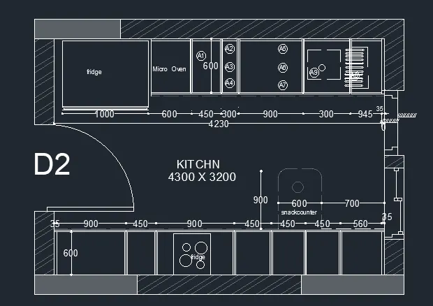
Result:
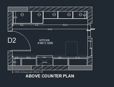
2):
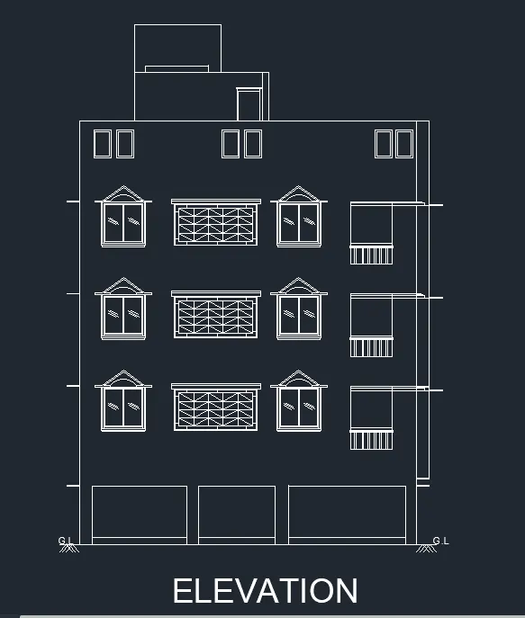
Aim: To create the elevation of the plan created in the Challenges 7.
Introduction: To create the elevation of the plan created in the Challenges 7. By using AutoCad
Procedure:
Step1:
- CREATION OF WINDOW
- First take rectangle of 1219x1219 next take the offset of 25mm to create the frame
- Next draw a line from the mid of above line then join with the two end to form a triangle shape structure and take the offset of 25mm

Step2:
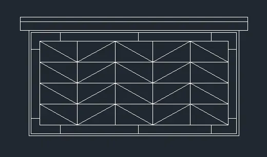
- CREATION OF 2ND WINDOW
- First take rectangle of 2419x2419 next take the offset of 25mm to create the frame
- Next divide rectangle into 5 segment and draw the from end point to end point to form a frame as shown
Step3:
- CREATION OF 3RD WINDOW
- First take rectangle of 1219x1894 next take the offset of 25mm to create the frame
- Next draw a horizontal line of from the window and make a offset of 100mm next draw a 6 lines with the offset of 50mm from the bottom of the windows as shown
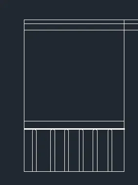
Step4:
- Draw a straight horizontal line with the length of 9873mm
- Next draw a three rectangle box an place it with an certain distance as shown
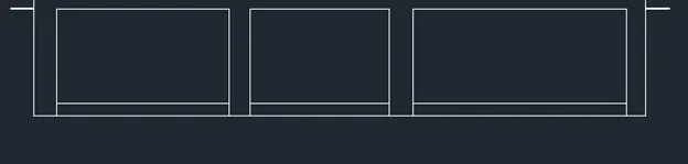
Step5:
- Now at the distance of 1219mm place the place the created windows
- At the height from the sell level select the windows take the move command and place it as per requirement
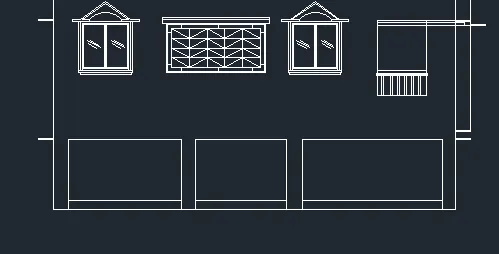
Step6:
- Now select all the windows and copy it one above the other up height of 3 floor
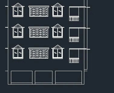
Result:
3):
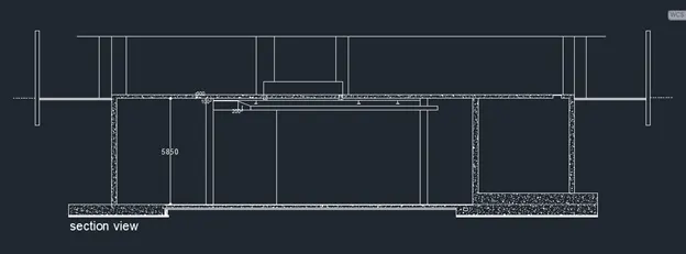
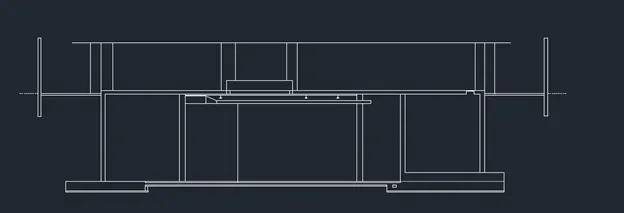
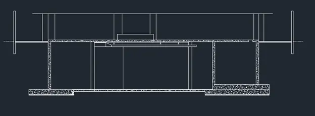
Aim: To Create the section view of an industrial building
Introduction: To Create the section view of an industrial building. By using AutoCad
Procedure:
Step1:
- Take a line command and mark a straight line of 25300mm
- Next take a vertical line of 5850mm.
- At he bottom area take a offset of 50mm for solid area hatching portion
- Next take the 300mm offset for the columns
Step:2
- Take the hatch command and select the AR CONC and fill the portion
Result: