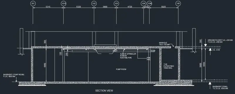
Creating Kitchen layout, Hatching of Architectural elements and sectional view of an Industrial Building in AutoCad
Initial procedure:
- Open AutoCad
- Select the metric system
- Set the Unit as Decimal with precision 0,0
- Now set the Limits, lower limit as 0,0 and upper limit as 1000,1000
- Type Zoom in the command prompt and select All.
1.
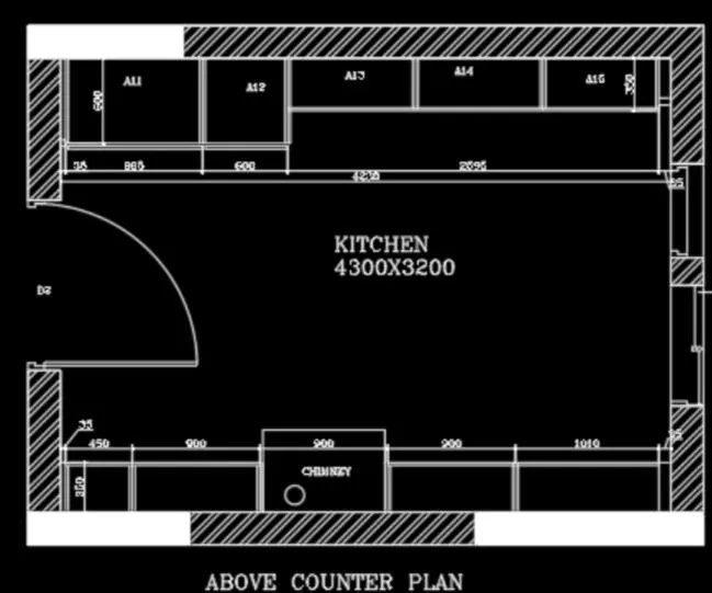
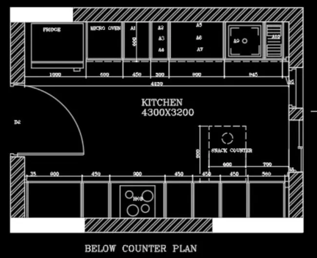
Aim: To create the layouts of the Kitchen and provide hatches pattern as shown in the figure
Procedure:
- Draw a rectangle of size 4734*3688mm
- Now draw a vertical and a horizontal line using XLINE command.
- Now offset the rectangle first, so that the brick work od 230mm is shown.
- Now offset 350,450,900,450,450,560 and 35 horizontally
- And offset 600 distance vertically
- Offset 700 distance from the right wall horizontally and 900mm vertically for snack counter
- For working platform1, offset 35,965,600,2595 and 35 horizontally and 600, 350mm vertically.
- For Working platform2, offset 35,450,900,900,900,1010 and 35 horizontally and 350mm vertically.
- Offset 12mm on both sides to the main offsetted lines to dimension it centre to centre
- Using ARC and LINE commands, the doors are created
- Niw using the RECTANGLE command and PLINE command to draw, fridge, sink, chimney is made
- Using CIRCLE command, sink hole, snack counter, hob, chimney is made.
- Now again using OFFSET command, draw Micro oven and other utilities.
- Using LINETYPE, we can change the continuous line to dash lines and can change the scale accordingly.
- Now , Use the TRIM command to trim off the unwanted lines.
- Using TEXT, we can insert the required text in the appropreate space.
- Dimensioning is done finally.
Result:
2.
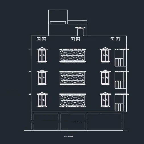
Aim: To create the elevation of the plan created in Challenge 7 and to apply proper hatch in the walls, doors, windows and other architectural element.
Procedure:
- Using the LINE command, draw the lines
- Now offset 150mm from the ground level and then 2450mm abaove it
- Offset 2850mm 3 times, so that the first, second and third floors are made
- Offset 100mm for the parapet wall.
- Elevation corresponding to the plan of the building is thus made.
- Using LINETYPE, we can change the continuous line to dash lines and can change the scale accordingly.
- Now , Use the TRIM command to trim off the unwanted lines.
- Hatch the figure, using HATCH command, use AR-CONC and solid with specific BLACK.
- For glasses on thw windows, the hatching is also done.
Result:
3.
Aim: To create the sectional view of the given industrial building, giving proper hatchings
Procedure:
- Draw the sectional view of the industrial building with the details given with the help of PLINE command
- Using LINE command, the ducts are drawn
- Using the RECTANGLE command, draw the rectanges of required size to represent the ducts
- Using the LINETYPE, the continuous lines are converted to Dotted lines and scale can be adjusted.
- Now Start hatching the section using HATCH command, Soild and AR-CONC for the concreted areas
- Using TEXT, we can insert any text of desired size and style at appropriate place.
- Dimensioning can be done finally.
Result: