Creating Kitchen layout, Hatching of Architectural elements and sectional view of an Industrial Building in AutoCad
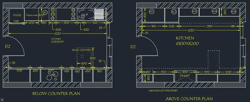
AIM: To create the layouts of the Kitchen and provide hatches pattern as shown.
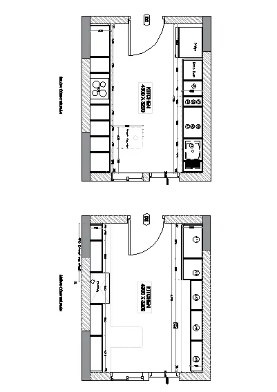
INTRODUCTION: Autocad is a software well designed for drawing 2D and 3D plans for the strutcure designs.
PROCEDURE:
1. Autocad software is opened and a new file is created.
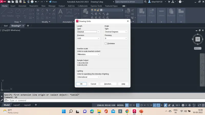
2. UN command is used to set the units to decimal.
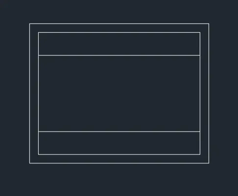
3. REC command is used and dimensions are selected then length is specified as 4734, width is given as 3688.
4. O command is used and then inner rectangle is drawn at 250.
5. L command is used and then a line is drawn at a distance of 600 both on top and bottom.
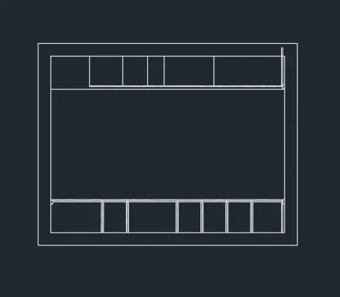
6. A rectangle of width 35 is drawn at 3 corners in order to separate between the kitchen walls and the counter.
7. L command is used to draw the rest cabinets.
8. C command is used to plot the hob line.
9. L command is used and then in the properties continous line is changed to dotted line and then snack counter is drawn.
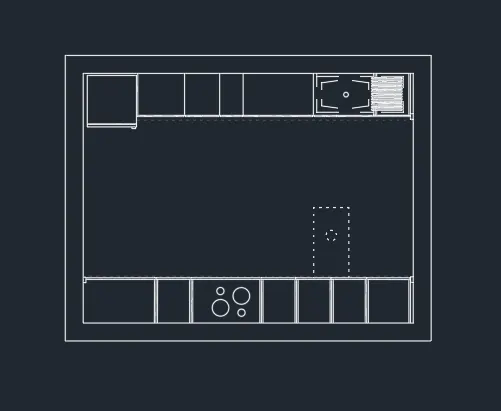
10. TRIM command is used and door opening is made and using L command is used and ARC command is used to draw the door for the room.
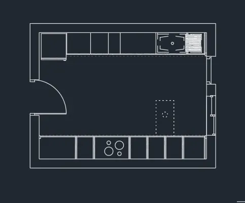
11. H command is used and from solid pattern is selected and then hatching is completed.
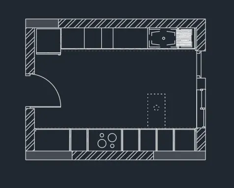
12. DIMLIN command is used to give the dimensions for the figure at the respective places.
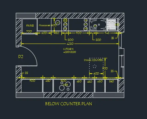
13. The process is followed for the above counter as for the below and the above counter is drawn.
14. CO command is used to copy the external walls.
15. Interior is drawn using the L command, C Command is used whenver required.
16. H command is used and from solid pattern is selected and then hatching is completed.
17. DIMLIN command is used to give the dimensions for the figure at the respective places.
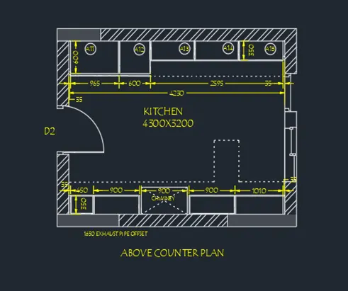
RESULTS: Both kitchens are created as per the figure using autocad software.
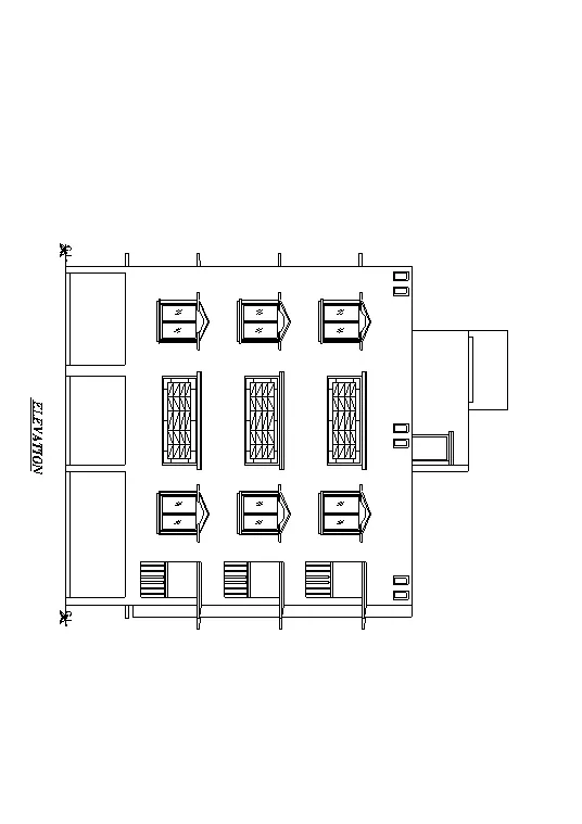
AIM: To create the elevation of the plan created in the Challenges 7 and apply proper hatch in the walls, doors, windows, and other architectural elements.
INTRODUCTION: Autocad is a software well designed for drawing 2D and 3D plans for the strutcure designs.
PROCEDURE:
1. Autocad software is opened and a new file is created.
2. UN command is used to set the units to decimal.
3. L command is used and the elevation is drawn same as per the challenge 7.
4. H command is selected and then hatch type solid and pattern is selected as per the figure and then hatching is done for the respective points.
5. After one hatching is done enter is clicked to complete that hatching.
6. Again H command is selected and then hatch type gradient is selected as per the figure and then hatching is done for the respective points.
7. After one hatching is done enter is clicked to complete that hatching.
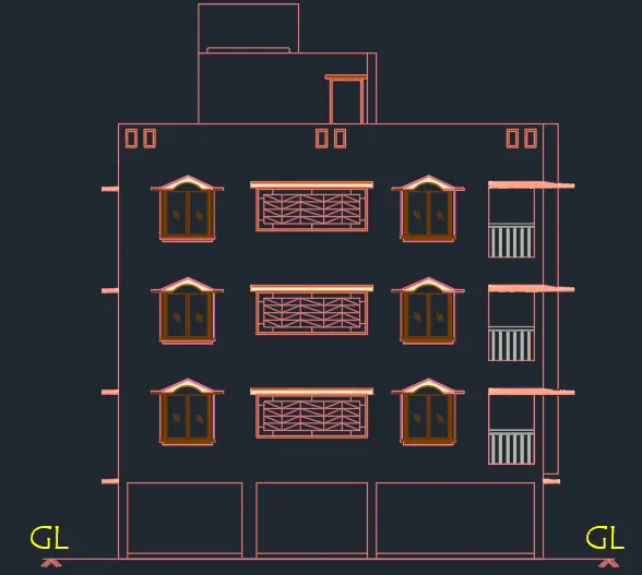
RESULTS: Elevation is hatched properly as per the given figure using the autocad software.
AIM: To create the section view of an industrial building as shown in Figure. Provide appropriate hatches and dimensions wherever required. Also, provide annotations to the drawing.
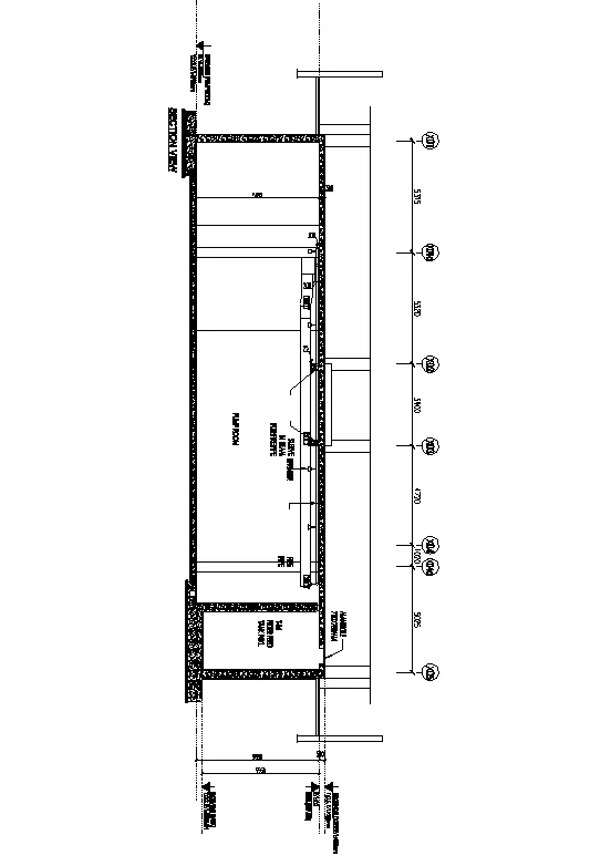
INTRODUCTION: Autocad is a software well designed for drawing 2D and 3D plans for the strutcure designs.
PROCEDURE:
1. Autocad software is opened and a new file is created.
2. UN command is used to set the units to decimal.
3. A layer is created by clicking on layer properties.
4. Now a new layer is created and name is specified as Walls and a colour is specified to identify easily.
5. Now using the L command, REC command, O offset command is used to draw as per the figure.
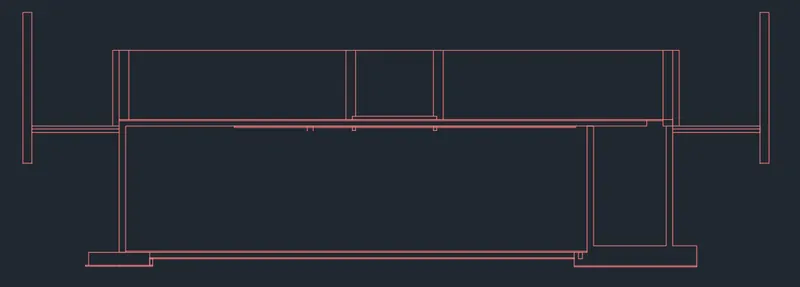
6. H hatch command is used to hatch the walls as per the figure is given.
7. Now hatch is chosen as per the figure and then the area is hatched at the specified location.
8. All the respective places are picked and hatching is completed.
9. Once hatching is done enter is pressed and hatching is completed.
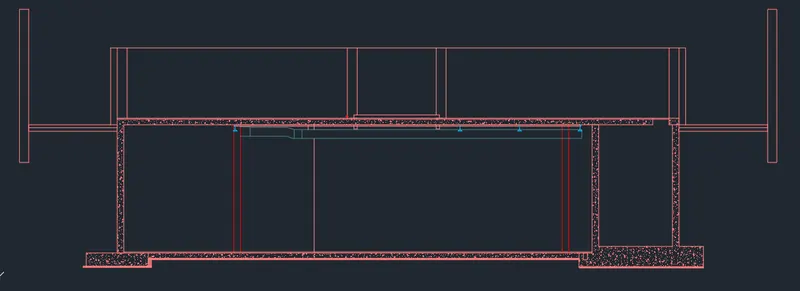
10. Again layer properties are opened, new layer is created and name is specified as text.
11. A colour is specified so that it can be specified clearly.
12. MTEXT command is used and then text is written as per the figure.
13. Again layer properties are opened, new layer is created and name is specified as dimensions.
14. A colour is specified so that it can be specified clearly.
15. DIMLIN command is used and dimensions are specified at respective places.
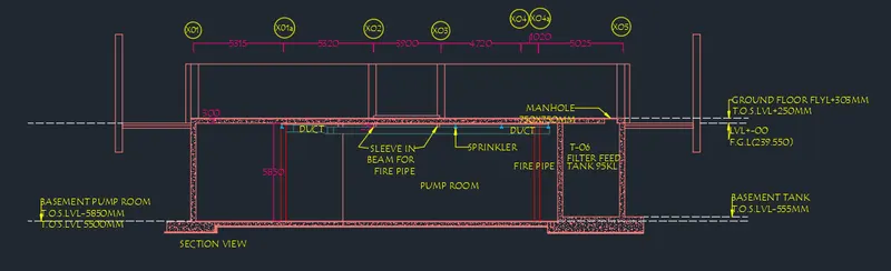
RESULTS: Using autocad as per the figure sketch is done and then dimensions are also speciifed.