Creating Kitchen layout, Hatching of Architectural elements and sectional view of an Industrial Building in AutoCad
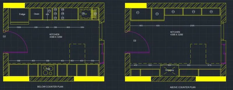
1) Aim :- To create a kitchen layout as given in the question
Procedure:-
- download the pdf file of the plan to be drawn. open a new cad file and make the units into mm .
- enter option xref - attach pdf - select the downloaded pdf file - press enter
- measure a dimension . we observe that the file downloaded is in a different scale
- to scale the drawing, enter scale option - select the object- select base point- select referance-the first length to be entered is the reference length ( the length that we measured in the file )- the second length to be entered is the new length( the actual length that we require.)
- make a layer and name it 'kitchen plan' ,to draw the elevation an dother details of the drawing.give it a colour yellow.
- now draw over the drawing using line option and marking the ortho mode on. rectangle option is also used for drawing.
- make another layer called 'text/dim' and give it a colour white, and then dimension our drawing using dimension option.use dimcontinue to get all the dimensions in a particular row or coloumn continously. write the required texts using text option.
- make a third layer called 'D/W', with a purple colour and then draw the doors and windows. similarly with doors also .
- make another layer and name it ' texts', and using text option write down the required texts.
- after completion of the drawing copy the drawing that we made and paste it separately
- the resulting drawing is as given below
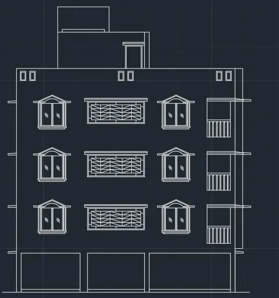
2) Aim :- To create the elevation of the plan created in the Challenges 7
Procedure:-
- download the pdf file of the plan to be drawn. open a new cad file and make the units into mm .
- enter option xref - attach pdf - select the downloaded pdf file - press enter
- measure a dimension . we observe that the file downloaded is in a different scale
- to scale the drawing, enter scale option - select the object- select base point- select referance-the first length to be entered is the reference length ( the length that we measured in the file )- the second length to be entered is the new length( the actual length that we require.)
- make a layer and name it 'elevation' ,to draw the elevation an dother details of the drawing.
- now draw over the drawing using line option and marking the ortho mode on.
- make another layer called 'text/dim' and give it a colour white, and then dimension our drawing using dimension option.use dimcontinue to get all the dimensions in a particular row or coloumn continously. write the required texts using text option.
- make another layer and name it ' texts', and using text option write down the required texts.
- after completion of the drawing copy the drawing that we made and paste it separately
- the resulting drawing is as given below
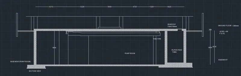
3) AIM:-To create the section view of an industrial building as shown in figure
procedure :-
- download the pdf file of the plan to be drawn. open a new cad file and make the units into mm .
- enter option xref - attach pdf - select the downloaded pdf file - press enter
- measure a dimension . we observe that the file downloaded is in a different scale
- to scale the drawing, enter scale option - select the object- select base point- select referance-the first length to be entered is the reference length ( the length that we measured in the file )- the second length to be entered is the new length( the actual length that we require.)
- now draw over the drawing using line option and marking the ortho mode on.
- then dimension the drawing using dimension option.use dimcontinue to get all the dimensions in a particular row or coloumn continously.
- using text option write down the required texts.
- after completion of the drawing copy the drawing that we made and paste it separately
- the resulting drawing is as given below