Creating Kitchen layout, Hatching of Architectural elements and sectional view of an Industrial Building in AutoCad
1.
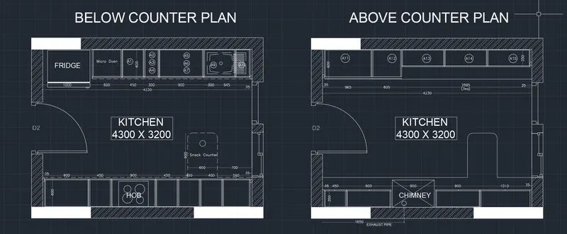
AIM:- Create the layouts of the Kitchen and provide hatches pattern as shown. Also, use blocks wherever required. Provide appropriate dimensions in the plan. Assume the size of doors, appliances and others as per the standards.
PROCEDURE:-
- At first attach the pdf in the autocad by using attach tool in the insert bar.
- Now scale the pdf according to the dimensions in written in the pdf.
- Now draw line on the lines shown in the pdf to create a replica of the kitchen plan shown in the question.
- Now give the notations using "DTEXT" command whereever needed.
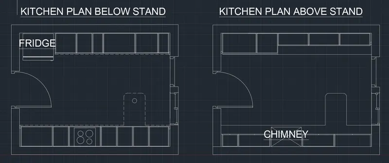
- Now add the text where ever needed using "DTEXT" comand.
- Now put the hatch type 'solid' for the columns to differentiate it from other things.
- Now put the hatch type 'ANSI32' for the wall shown in the drawing to differentiate it from other items.
- Also put the dimensions of each and every item to show it's size.
- Also put the text showing the size of the kitchen and other antities.
--------------------------------------------------------------------------------------------------------------------------------
2.
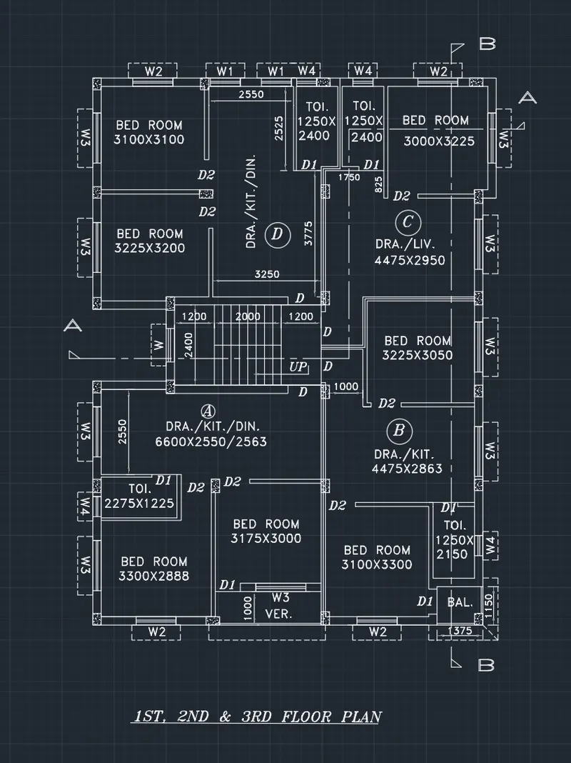
AIM:- Create the elevation of the plan created in the Challenges 7 and apply proper hatch in the walls, doors, windows, and other architectural elements. Refer to the dimensions in Plans and sections in Challenges 7.
PROCEDURE:-
- At first attach the pdf in the autocad by using attach tool in the insert bar.
- Now scale the pdf according to the dimensions in written in the pdf.
- Now draw line on the lines shown in the pdf to create a replica of the building plan shown in the question.
- Keep the attached PDF in the underlay.
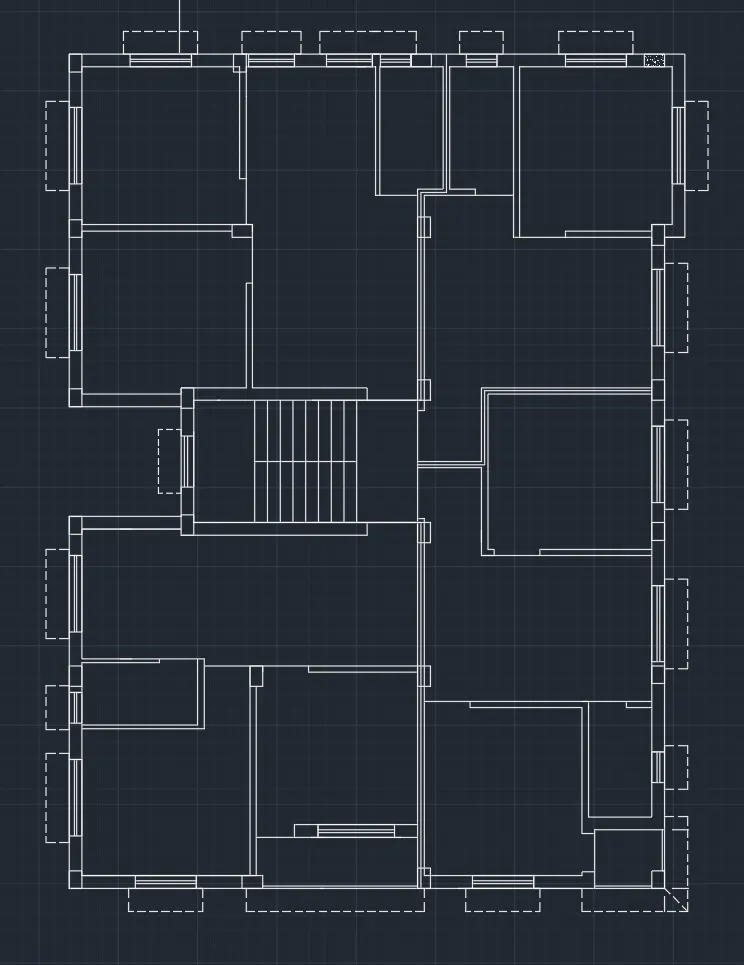
- Now add the text to show the name and size of the respective room in the different layer.
- Add the text using "DTEXT" command.
- Add section line "AA" and "BB" as shown in the figure.
- Give section line different layer to differentiate it from other lines.
- Add "HATCH" to the shown columns and select hatch type "AR-CONC"
- Use Leader option where needed. For Ex. to show the up and down direction of the stair.
- Now for "ELEVATION" draw a vertical line using command "XLINE".
- Now draw a horizontal base line instersecting the first and last XLINE and name it as "G.L.".
- Now draw the whole section using commands like "LINE", "OFFSET".
- Assume height of the "STILT FLOOR" as 2450mm and all other floors as 2850mm.
- Height of parapet wall as 1000mm.ETC.
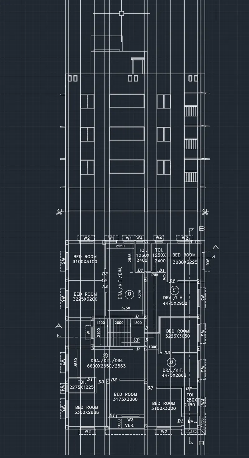
- Now remove all the "XLines" and then give the text to the drawing as needed with "DTEXT"
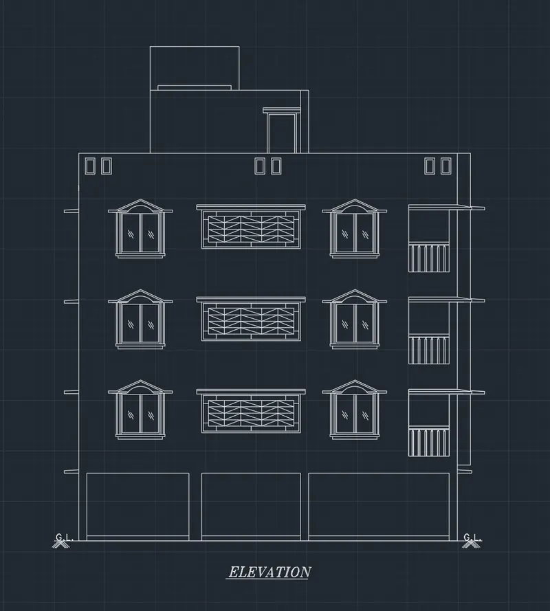
- Now give the hatctes to the door and window to make it appropriate for everyone to study the elevation drawing.
- The final drawing should be as below.
---------------------------------------------------------------------------------------------------------------------------------
3.
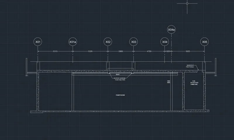
AIM:- Create the section view of an industrial building as shown in Figure. Provide appropriate hatches and dimensions wherever required. Also, provide annotations to the drawing.
PROCEDURE:-
- Draw a rectangle of the size "25600 X 6300mm".
- Now Give the offset of 300mm to the whole rectangle to give it the width of the wall.
- Now mark the Gridline as shown in the figure at the given dimensions.
- Now put the lines using Gridlines asshown in the figure to show the sprinklers.
- Also name the Grids as shown in the figure and it also makes easy to draw the whole drawing.
- Also by using commands like line, offset, expand & trim complete the following drawing.
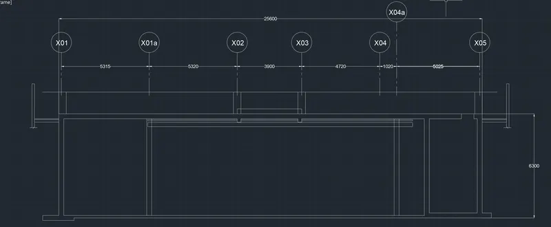
- Now put the hatch where the concrete work is to be done to differentiate it from other parts of the drawing.
- Now put the Leader for the substances where it is needed.
- Where there leader is not needed use "DTEXT" to notate the antity.