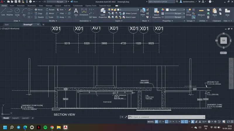
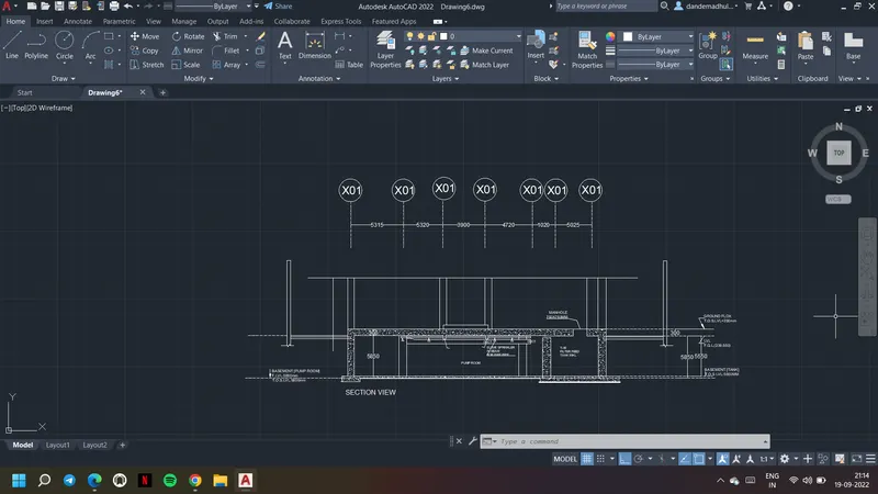
Creating Kitchen layout, Hatching of Architectural elements and sectional view of an Industrial Building in AutoCad
Aim & Introduction: To draw kitchen layout of a building. Below counter plan and above counter plan both are drawn. Text and dimensions are inserted accordingly using comamnds.
Procedure:
1. Open the AutoCAD drawing and give command units. Choose units as decimal and millimeters as shown.
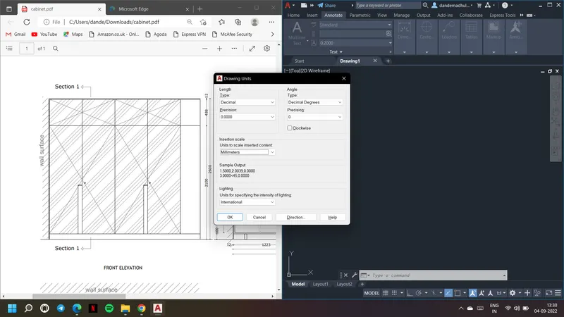
2. Draw below counter plan first using line command. Draw the lines with respective distances as given.
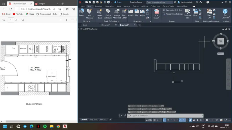
3. Offset them using offset command.
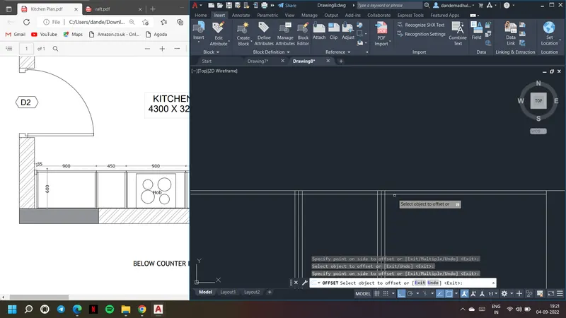
4. Draw the outer layer i.e.,layout of kitchen as shown
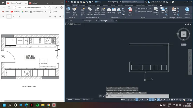
5. Import kitchen layout pdf and crate block for the door.
6. Insert the door into the drawing. Use scale command and sclae the imported door as required.
7. Else draw a door and create a block for that and insert it.
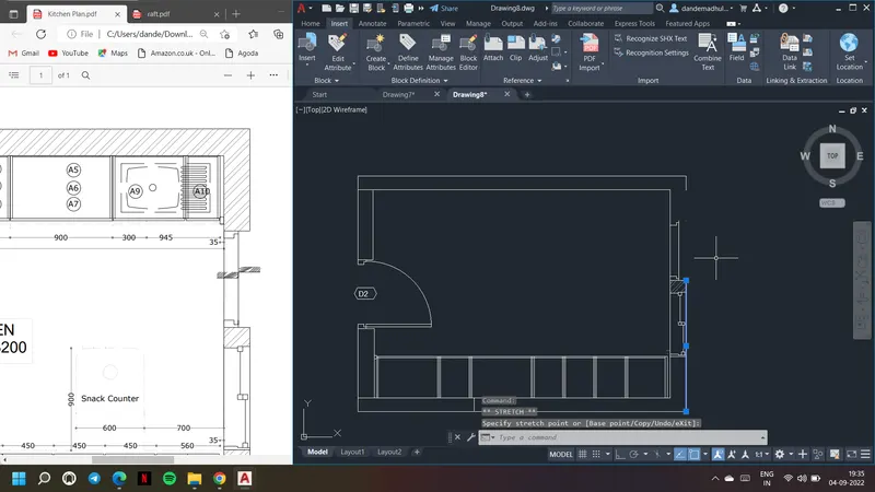
8. Chnage the linetype and set it as current and draw snack counter as shown.
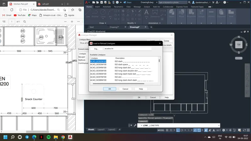
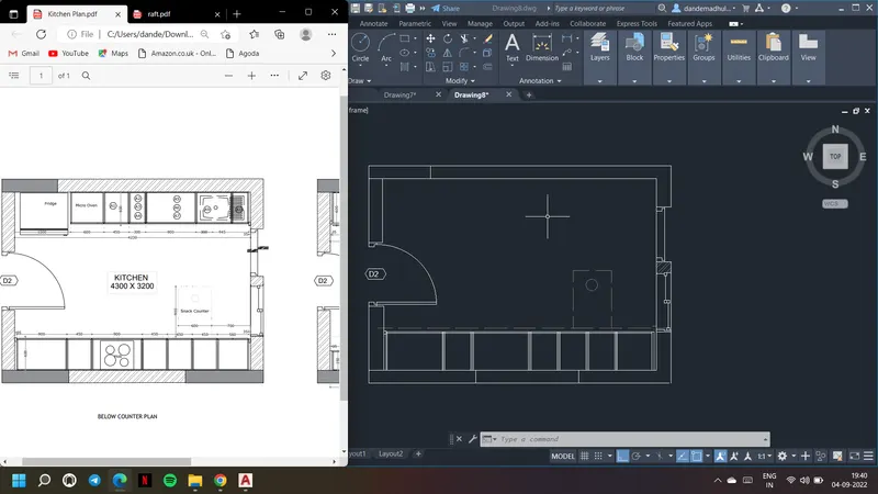
9. Draw all other parts of kitchen i.e., fridge micro oven etc.
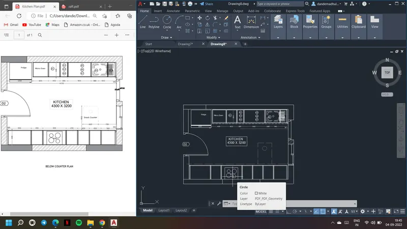
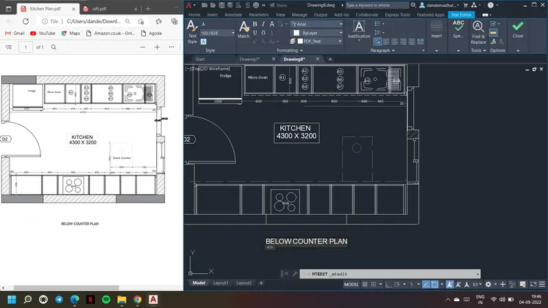
10. Use dimlinear or dimcontinue to show the measurements/ dimensions. Use Mtext or text comamnd and provide the text wherever required.
11. Use hatch command. Go to hatch settings to choose hatch type and scale. Provide hatch wherever required.
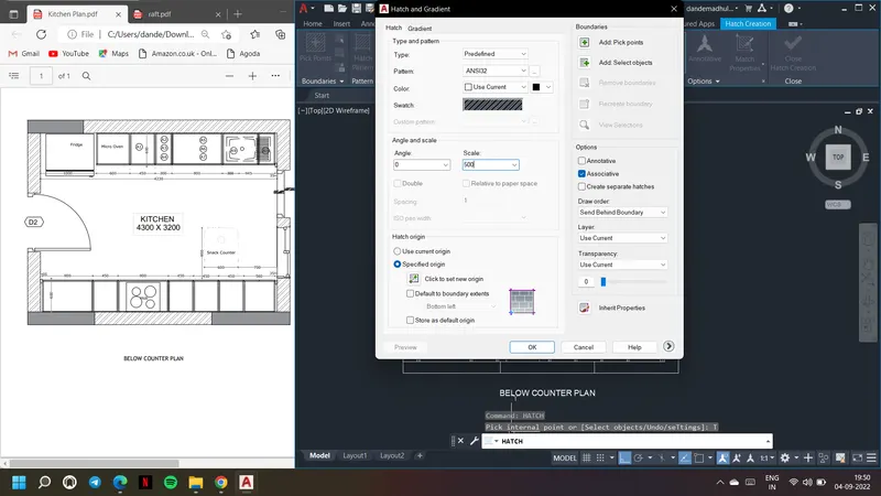
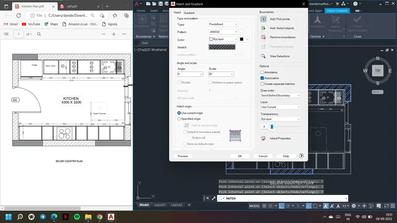
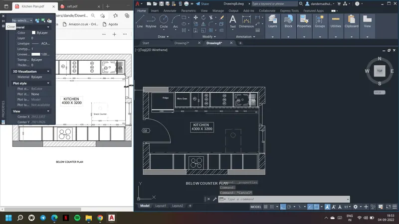
12. Can also got to properties and set the scale of the hatch as shown.
13. Copy the below counter part of kitchen drawn. Paste it and edit it accordingly to form the above counter part of kitchen as shown.
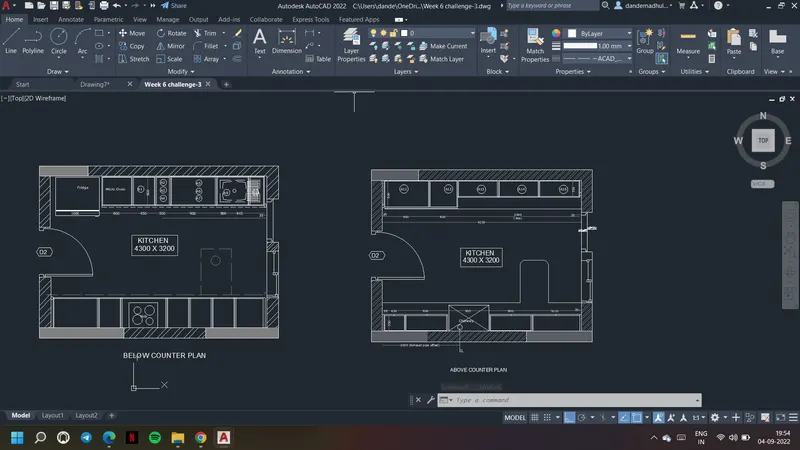
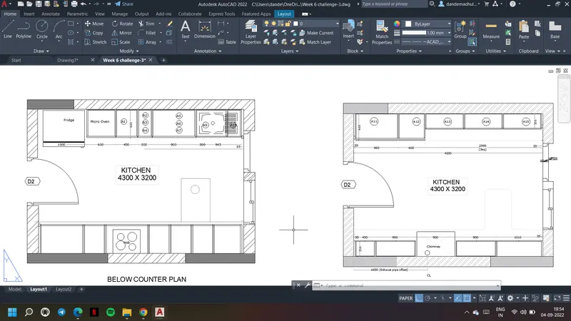
Result: Drawing of the Kitchen Layout
Aim & Introduction: Elevation of the plan created in the Challenge 7 needs to be created. Hatch command is used to hatch in the walls, doors, windows, and other architectural elements. Elevation is drawn using dimensions of the plan in challenge 7.
Procedure:
1. Section BB pf challenge 7 is taken as it is the elevation of the plan of challenge 7
2. Make the changes by extending the lines as required.
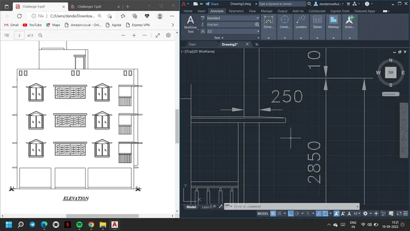
3. This elevation is drawn with reference to plan of challenge 7
4. Else section BB if challenge 7 can be taken and modified
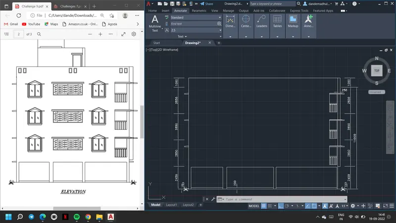
5. Draw the ventilators as shown using rectangle an doffset command.
6. Copy and paste wherever required.
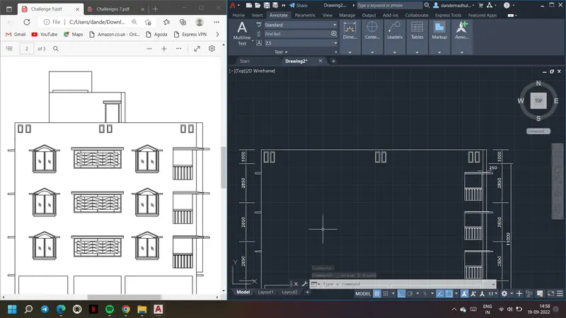
7. To draw the middle window line command, ortho mode is used.
8. Use trim command and trim the extra parts.
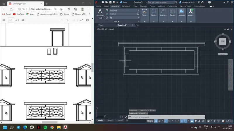
9. Divide command is used to divide the line as shown below.
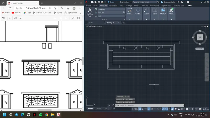
10. Use the points lines are drawn as shown below
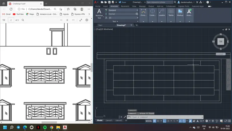
11. The middle window is formed and use copy paste options to paste it twice.
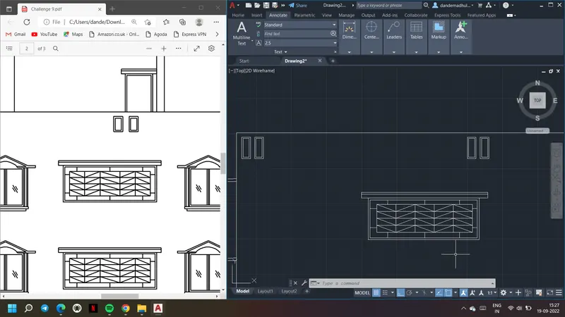
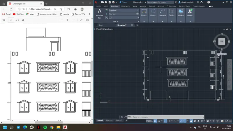
12. The other window is drawn using line, offset command.
13. Use trim command to trim the extra parts
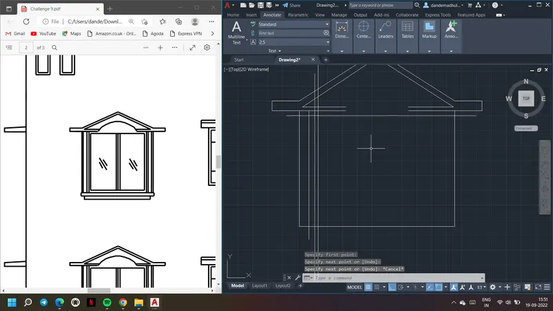
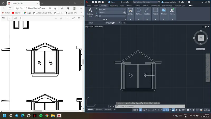
14. Over head tank is also drawing using line comamnd
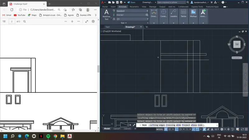
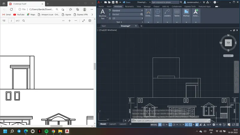
15. Copy the window drawn and paste it wherver required
16. Else create a block for the drawn window and insert it wherver required
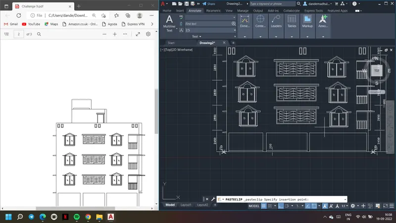
Result: Elevation of the plan created in the Challenge 7 was created.
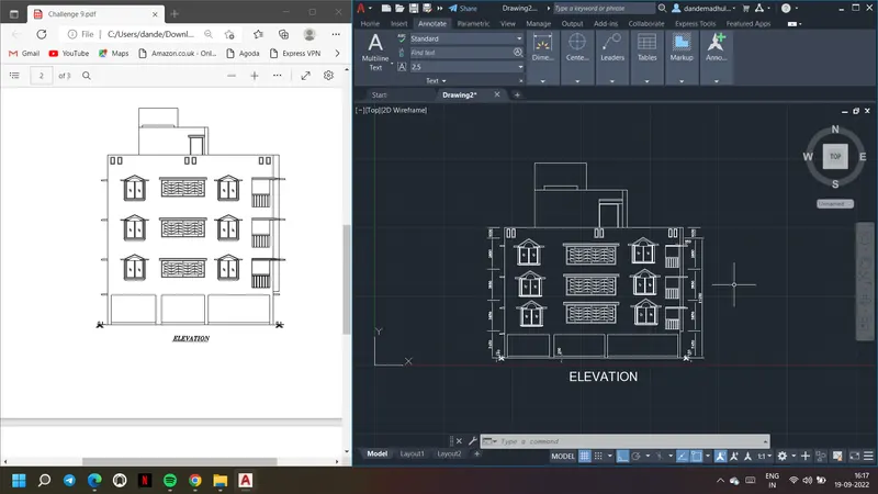
Aim & Introduction: To create the section view of an industrial building. Hatch and dimlinear command is used to insert hatch portions and dimensions wherver required. Leader, text, mtext commands are used to insert text.
Procedure:
1. For the sectional view draw the ground level, plinth level and lintel level as shown.
2. Draw the grids given at given distances to make the drawing easier
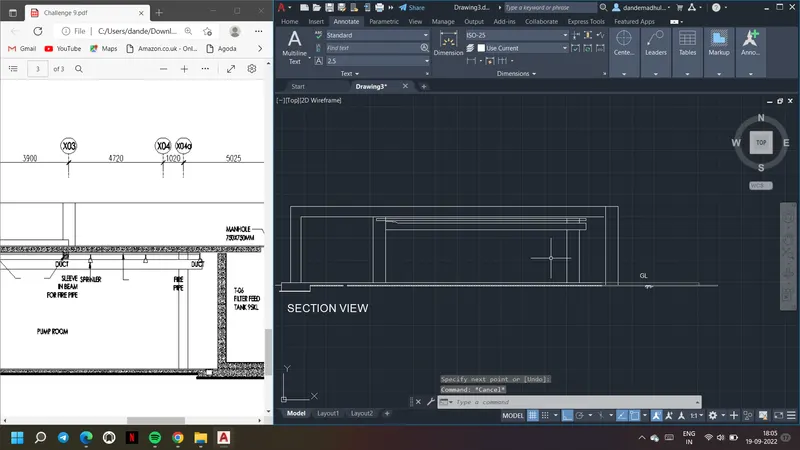
3. Use the line command and ortho mode and draw the other lines
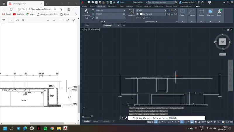
4. Change the line type wherver required and use extend command if a line needs to be extended
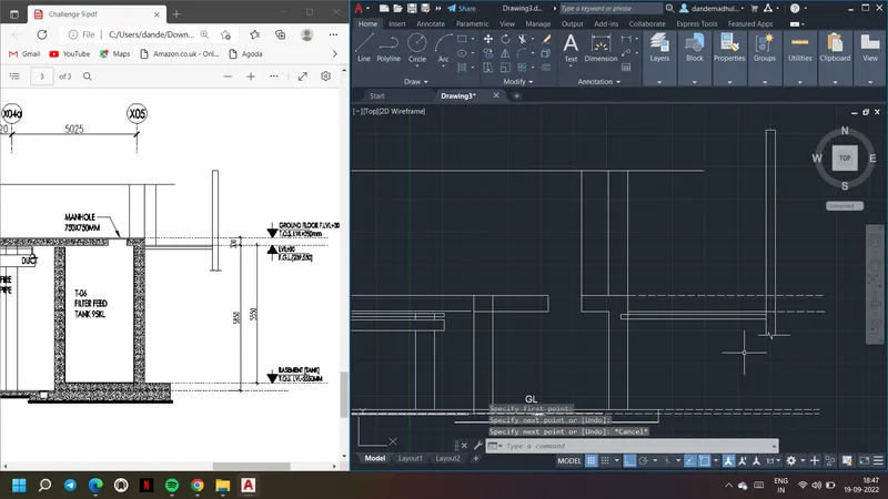
5. Use text comamnd and insert the text wherver required
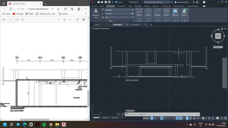
6. Use leader command and insert leaders and using mtext insert the text as shown
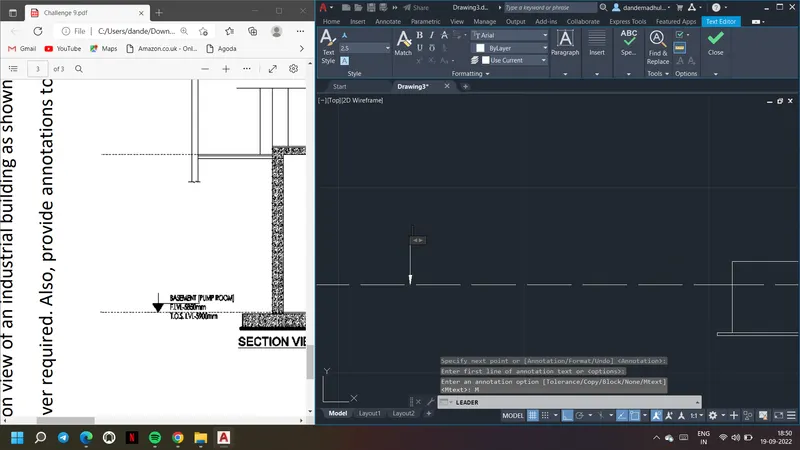
7. Change the arrow head height and text height by going into properties if required
8. Use hatch command and hatch the required parts, use the hatch settings accordingly
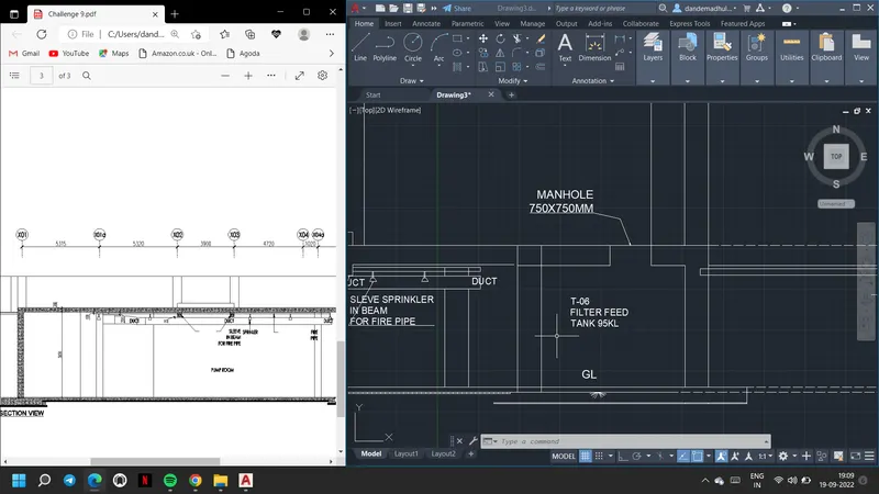
Result: The sectional view of an industrial building