Creating Kitchen layout, Hatching of Architectural elements and sectional view of an Industrial Building in AutoCad
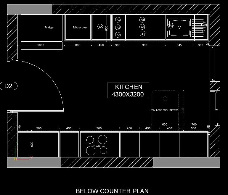
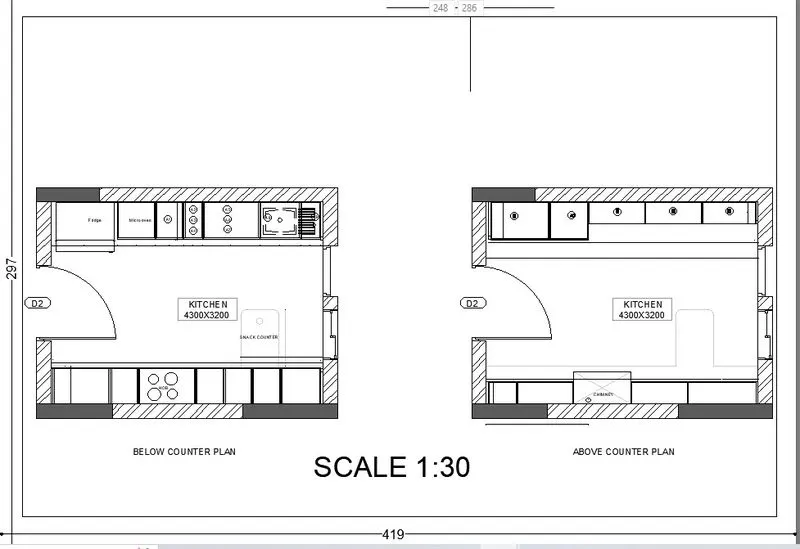
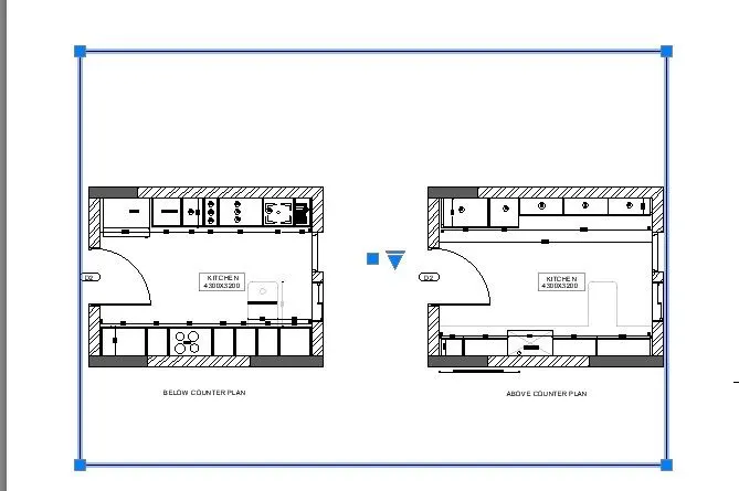
Aim: To Create the layout of the Kitchen and provide hatch to it.
Software that i have used: AUTOCAD
Tools i used
Hatch
line
mirror
copy
polyline
dimensions
mtext
block
trim
offset
array
attribute
view
multi viewports
layouts
multiline
procedure:
- Type mlstyle command and create a new style as skill lync.
- Take elements with the offset distance of 125 and -125 .
- Type ml command in the command box draw the line in x-axis with distance 4760 and in y-axis with distance of 3660units.
- repeat the procedure in opposite direction make it in close.
- go to mledit and take operation of cutline and cut the multiline wherever required.
- Take hatch command shows the section of wall in plan.
- Take offset command make shelfs and furniture with offset distance of 1000,600,450,300,900,645,300 in y-axis .
- same procedure is repeat in the opposite direction with a distance of 900, 450,900,450,450,450,560.
- provide the space at each corner with 35 units
- width of shelfs is 600 units.
- after creating the transform make it into block .
- windows are also transform in to block.
- provide the dimension wherever required before that create new dimstyle for your own.
- some lines turns in to hidden and make transperancy low to it .
- after completing the kitchen plan in the model .
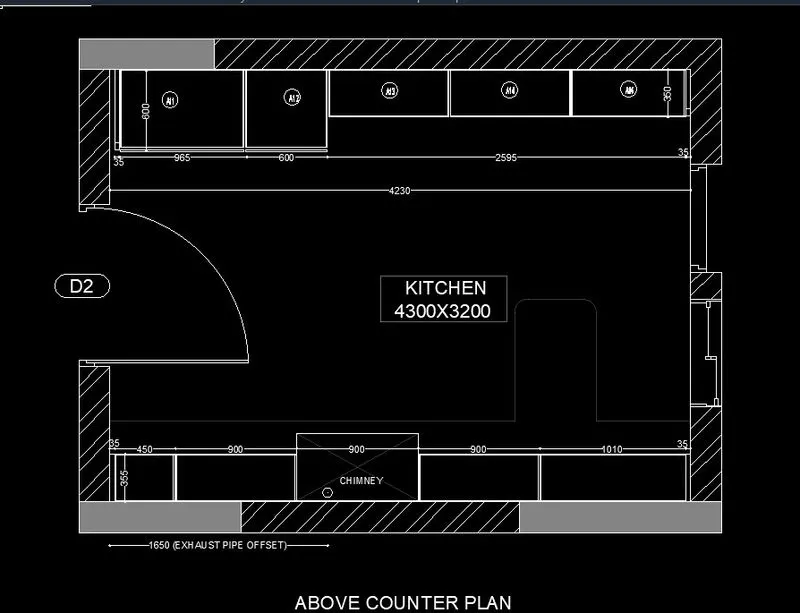
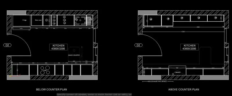
- take copy command and replica has to place in near it.
- made some changes like placing chimney and changing dimension of furniture and shelfs .
- we have completed the above and below counter plan in the model.
- type layout in the command box and create the new layout with a name of kitchen.
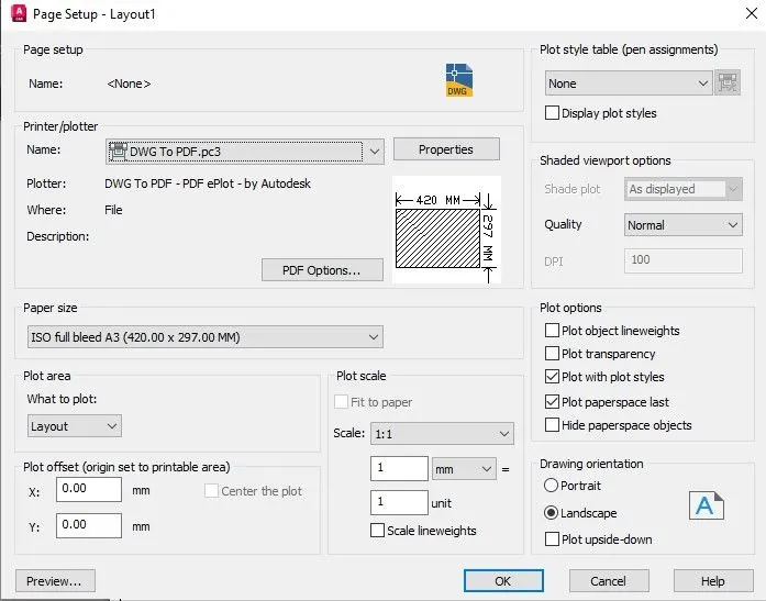
- right click of the layout popup will appear go to the page setup manager and select the paper size in which layout plot in to it.
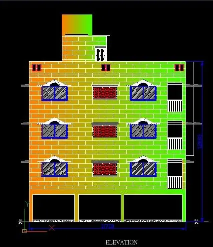
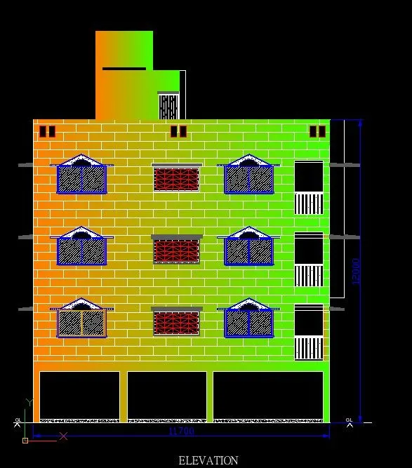
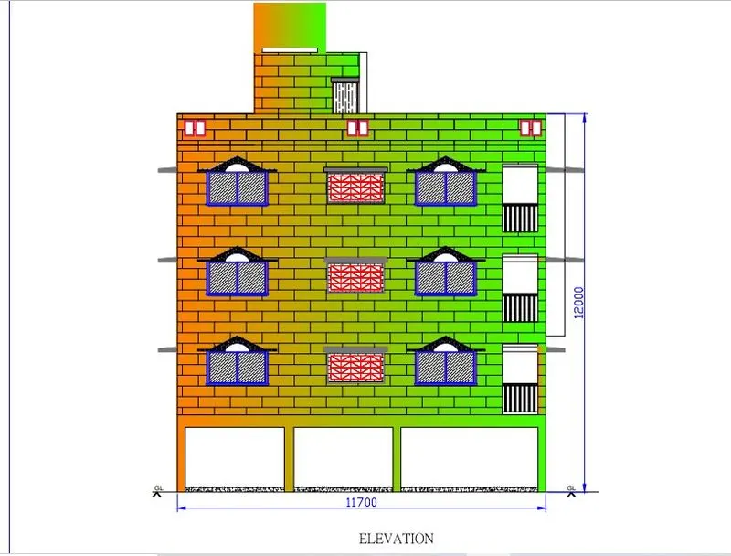
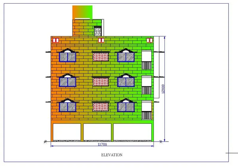
Aim: To Create the elevation of the residential plan and apply proper hatch in the walls, doors, windows, and other architectural elements.
Tools i used
Hatch
line
mirror
copy
polyline
dimensions
mtext
block
trim
offset
array
layers
PROCEDURE:
- open the metric format new drawing file.
- take x reference command and select the previous drawn residential buiding plan and section.
- insert into current drawing .
- we can see in the plan what are elements in the front .
- take ray command project the front elements position lines of the residential building plan.
- with the help of section dimension draw the each floor layer by layer.
- take an offset command draw the lines in the horizontal direction with distances of 2450,2730,2850,1000,1500,1200.
- providing the windows postions according to the plan .
- window dimension -1800x 1000.
- by using copy option place the window in the another floor.
- at the each there is one balcony it is made by using line, trim and array.
- paste same replica in the each floor.
- At the terrace there is one room over over head tank is provided with the use of offset, line,trim tools.
- dimension are provided to it with the proper scale.
- type h command in the command line.
- go to setting select the island detection at outer.
- go to pattern and select the material that i want to assign.
- take AR-BRstd applied to the walls and also gradient with combination of orange and green.
- for the window panel i give the glass pattern.
- for balcony enclosement i used the steel pattern.
- for door i used wooden pattern.
- for sunshade i used solid with gray pattern
- for wood frame i used solid with color brown.
- for wood roof i used escher.
- for grade slab i used concrete pattern
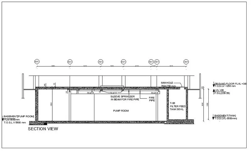
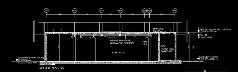
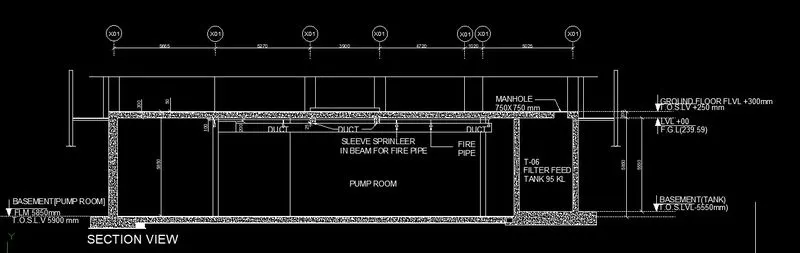
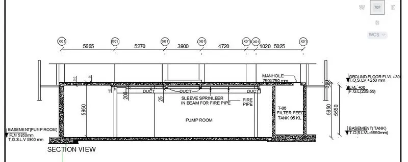
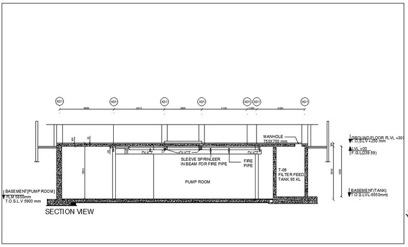
Aim: To Create the section view of an industrial building and hatching to it.
Tools i used
Hatch
line
mirror
copy
polyline
dimensions
mtext
block
trim
offset
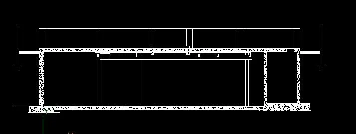
PROCEDURE:
- take a line command draw the horizontal line with a distance 25600.
- take a offset command draw line with offset distance of 300 units.
- draw the line in vertical with reference to the first endpoint of starting line in ransom distance .
- take offset command draw the vertical line with a distance of 150,5665,5270,3900,4270,1020,5025.
- provide 150 to the left of the first vertical line.
- draw the vertical line in downward direction with reference to the 150 left with distance of 5850.
- provide 300 offset to that line.
- At the 5665 end line draw the 100 unit thick line below the 300 units.
- with reference to the 300 units draw 200 thick line under .
- with reference to the 5665 end line draw the vertical line with offset 150 to right and 150 to left.
- at the top middle provide sleeve sprinkler with the specify of 200@270,20@180,150@270,25@180,50@270,115@0 by using mirror make it close.
- another should be placed at the distance 3900.
- ducts are made with the dimension of 300x300 units reference 3900 end lines under the 300 thick line.
- draw the 400 thick line under the 200 line for the duct support.
- provide the sleeve sprinleer near to the duct.
- fire pipe is provided under the1020 endline.
- man hole is provided inital stating of 5025 endline.
- filter feed tank with the inner dimension of 3000x 5550.
- dimensions are provided wherever required.
- text is used for information and detailing of the element.
- Go to h command take concrete pattern and applied to the support elements.
- blocks with attribute is used for making the end to end indication symbols.
RESULT: I have Created the layout of the Kitchen including hatching.
I have Created the elevation of the residential plan and applied proper hatch in the walls, doors, windows, and other architectural elements.
I have Created the sectional view of an industrial building include hatching.