Creating Kitchen layout, Hatching of Architectural elements and sectional view of an Industrial Building in AutoCad
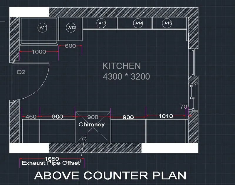
AIM: Create the layouts of the Kitchen and provide hatches pattern as shown. Also, use blocks wherever required. Provide appropriate dimensions in the plan. Assume the size of doors, appliances and others as per the standards.
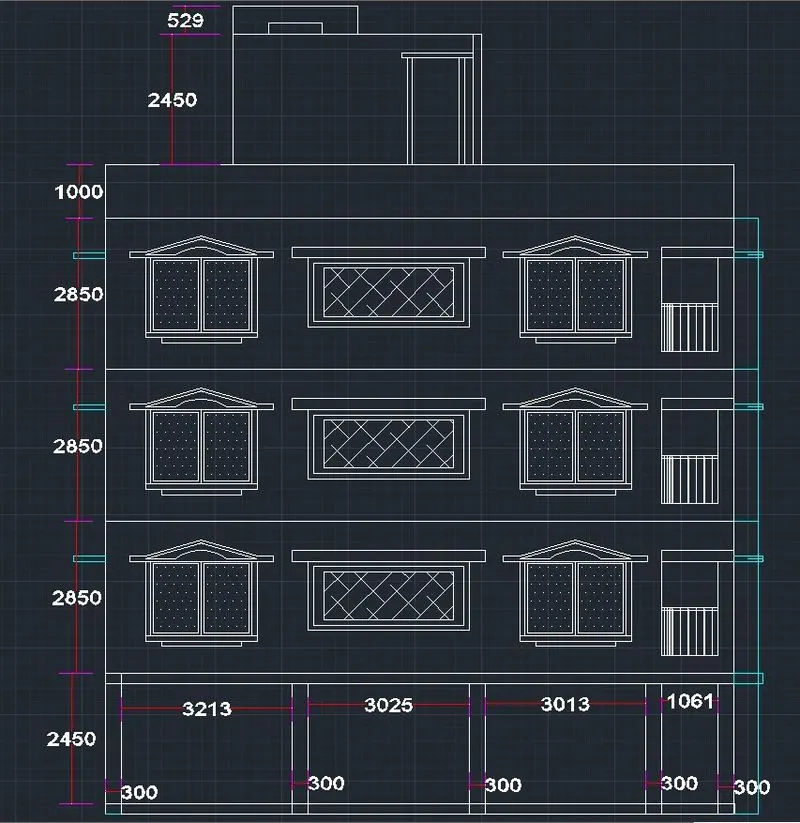
(b). Create the elevation of the plan created in the Challenges 7 and apply proper hatch in the walls, doors, windows, and other architectural elements. Refer to the dimensions in Plans and sections in Challenges 7.
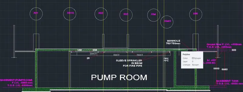
(c). Create the section view of an industrial building as shown in Figure. Provide appropriate hatches and dimensions wherever required. Also, provide annotations to the drawing.
INTRODUCTION:
1. All the sketches are drawn in the same unit with precision of "0" having lightning option in "generic form".
2. Sketches in the following are made keeping in view the perpection of an observer i.e., Observer viewing the drawing from the specific face is allocated the same colour covered by his eye.
3. Labelling & Texting is done by defining the annotative properties such as Text height 250; Text Style Arial;
Lines: Extension from dimension line =255; offset from the object= 230
Symbols & Arrows: Arrow head 150; Closed filled on both sides
4. Figure(a&b) of below attached drawing have an offset of 5mm on both sides whereever dimensions are not annotated/labelled.
5. Lines command nested within tra is used in most part of sketching.
PROCEDURE:
FIGURE(a):
1. Here D2 door of dimension 1020mm outer to outer, is created as a block with flipping option on both sides perpendicular to each other.
2. A circle of radius 100 units enclosing a label/text, is created as a block preceeded by attdef command.
3. Every time to attach above circle , we use insert "I" command and specify the location on the screen.
4. It's Better to commend the drawing from thr outer side to inner side for eliminating the human errors/mistakes.
5. Outer walls are of 250 units dimension, followed by hatching pattern with scale of 5 in the hatching settings.
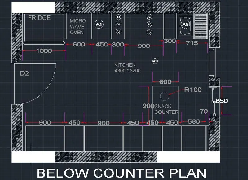
6. sink outer lines are offseted with a distance of 50 mm from all four sides while inner boundary lines have fillet with a radius of 25 units.
7.
FIGURE(c):
1. Firstly Draw the Grid lines by keeping the floor plan above the required sketch.
2. After putting the drawing at the required location, Use "RAY" command at the corners of the plan for tracing the elevation.
3. After Drawing the rays at the required position/corners, join the lines with another line of different layer lead to development of the base of the structure.
4. Here Floor Ground slab is of 200 unit dimension.
5. All the Dimensions are mearsured from the Floor to floor where the user will put his legs.
6. Sides components of the Building are drawn with the cyan colour to identify the structure.
7. Windows Projection on both sides are of 300 units on both sides while minimum offset from the ceiling is about 750mm.
8. Here WE have used MI, arc(start,end,direction), hatch,copy command with maximum utility.
9. Balcony Railings are of 10 mm thick steel rod with spacing of 150 mm centre to centre.
FIGURE(d):
1. Firstly Draw the Grid lines with required precision preceeded by changing the layer of the line.
2. After Sketching the Grid lines perpendicular to each other in both the direction, Walls are Drawn using an offset command of 150mm on both sides making the total wall thickness of 300mm.
3. Horizontal Grid lines are essential for levelling the structure so it's mandatory to follow after the vertical grid lines.
4. After Drawing the sketch using Line and tra command, it's Better to do the hatching with ANCI:88 concrete whereever is required.
5. Below the Reference horizontal grid line, a steel rod of 100 mm thickess is drawn with an offset of 50mm on both sides of this rod.
6. A duct of 500 mm dimensions is passing below the reference grid line with an offset of 275mm from the soffit of the base slab having minimum dimension of 25mm from bottom most point of the slab monolithic with t-beam within it.
7. Here circles of 250mm raddii are enclosing the text, defined through attdef command followed by Block command for labelling the GRID LINES.
8. After Sketching the Drawing, it is required to give the dimensions from the reference horizontal grid line.
9.
RESULT:
All the above sketches are drawn in the AUTOCAD software and after this, screenshots are attached here in the form of "JPEG" format using SNIP option.