Creating Kitchen layout, Hatching of Architectural elements and sectional view of an Industrial Building in AutoCad
Week 10-Assignment 9-Module 2
Aim: To create a Creating Kitchen layout, Hatching of Architectural elements and sectional view of an Industrial Building using the proper drawing techniques and editing tools with the aid of AutoCAD.
Introduction:
- The topics covered in week 10 (titled Design Center and Tool Palettes Concept) which are somewhat essentials in plotting the requested geometries are as follows;
- Layouts, this is the Display of one or more scaled views of your design on a standard-size drawing sheet called a layout. After you finish creating a model at full size, you can switch to a paper space layoutto create scaled views of the model, and to add notes, labels, and dimensions. You can also specify different linetypes and line widths for display in paper space.
- Layer properties manager, this helps you organize, sort, and group layers, and allows you to work with layer standards, layer key styles, layer filters, layer overrides, and saved layer states.
- Page set up manager, this to control layout settings and plotter properties. Page setups can be saved and applied to multiple layouts in the same drawing file. This also allows you to display the current page setup, sets a different page setup as current, creates a new page setup, modifies an existing page setup, and imports page setups from other drawings.
- Multiline option, multilines are objects that can consist of up to 16 parallel lines. The individual lines in a multiline are called elements. Like polyline segments, several connected multiline segments form a single object. Draw multilines using the MLINE command. This is useful in plotting utilities such as pipes and ducts.
- Revision cloud, is a geometry used in AutoCAD to drive attention of users to a certain part of the drawing. The revision clouds are Polylines in the shape of connected arcs and they can also be modified like a Polyline.
- Purge command, it removes unused named objects, such as block definitions and layers from the drawing. In short it optimizes the drawing files in AutoCAD.
- Group command, it makes the multiple objects made to act as a single object. By default, selecting one object in a group causes the entire group to become selected. Groups are saved with the drawing. Objects can be members of more than one group, and you can nest groups, which means a group can contain another group.
- Tables, the able command in AutoCAD is used to insert the table containing rows and columns. We can resize the rows and columns and can also stretch the entire table. We can insert the appropriate data in rows and columns according to the requirements.
Procedure:
A. Setting the Drawing Parameters;
- Set up the measurement units as metric measured in millimeters.
- To set up that, a much faster way is to type “units” in the command line and hit enter or space bar. The Drawing Units Dialog box will then pop up and measurement parameters will then set up in line with the requirements. Similar thing, you need to set up the dimension through the DDIM command.
- As for the gridlines, you may right click gridline icon in the status bar and go for the drafting settings. Under the Snap and Grid of the Drafting Settings Dialog box, you may set up the needed spacing of grids along its X and Y axis. “DS” command will also work to pop up the Drafting Settings Dialog box.
B. Starting the exercise;
- Combination and manipulation of all the different coordinate entry methods, drawing and modifying tools learned from weeks 1 to 10 were being used here in the completion of all the exercises given and result as pasted below.
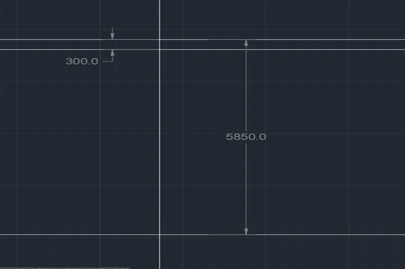
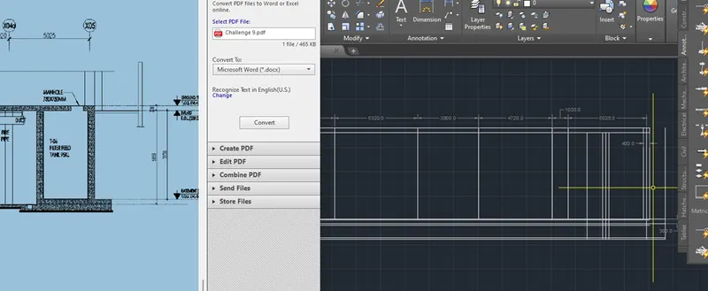
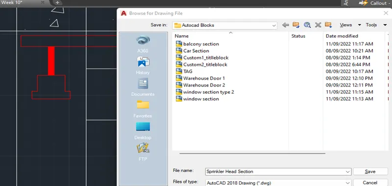
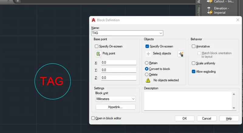
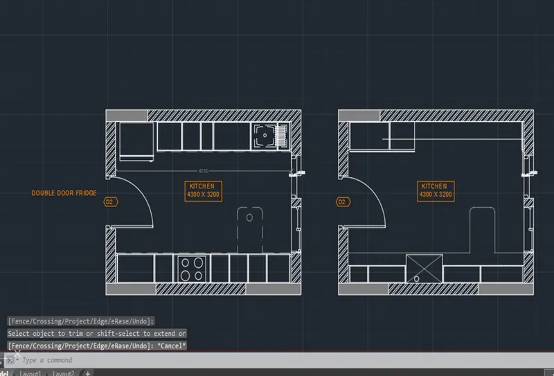
- I have attached some screenshots while plotting the needed Drawings to show the procedure on how it was done to come out with the requested Design layouts.
C. Challenge;
- In general, below commands/functions were being used while working on the exercises.
- Units
- LIMMAX
- DDIM
- XLINE
- LINE
- PLINE
- OFFSET
- DIVIDE
- PTYPE
- MIRROR (MI)
- CIRCLE
- FILLET
- MTEXT
- DIM
- Manipulation with Ortho mode and Object Snaps
- LAYERS
- UTILITIES
- MATCHPROP
- ANNOTATION
- PDF IMPORT
- RAY
- DIMBREAK
- COPY
- SCALE
- BLOCK/ BLOCK EDIT
- WBLOCK
- ATTRIBUTES
- ARRAY
- HATCH
Challenge 1: Below are the brief steps while working on the requested sketches.
- Set up the Units, Limits and Layers.
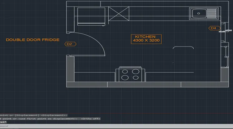
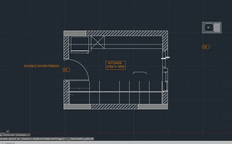
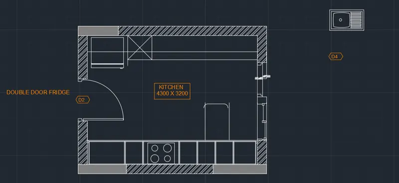
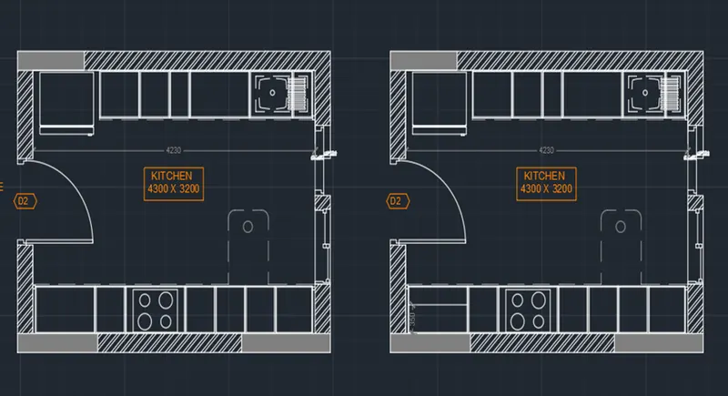
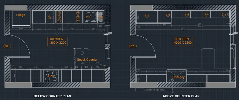
- Start with the below counter plan of the kitchen. Plot the walls using Construction Line or Draw commands together with the offset, trim, fillet and erase as applicable following the given sketches’ dimensions.
- Proceed with the door and window with the aid of the basic drawing tools of AutoCAD.
- Kitchen amenities to follow.
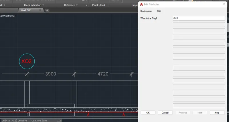
- Then proceed with Annotations and it can be done also with the help of Attributes and Blocks.
- As for the above counter plan, it can be drawn fast by duplicating the result of the below counter and only edit/ modify the kitchen amenities part including its annotations.
Challenge 2: Below are the brief steps while working on the requested sketches.
- Open the previous Challenge No. 7 Drawing as such activity was based on that.
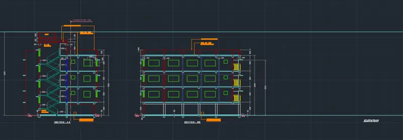
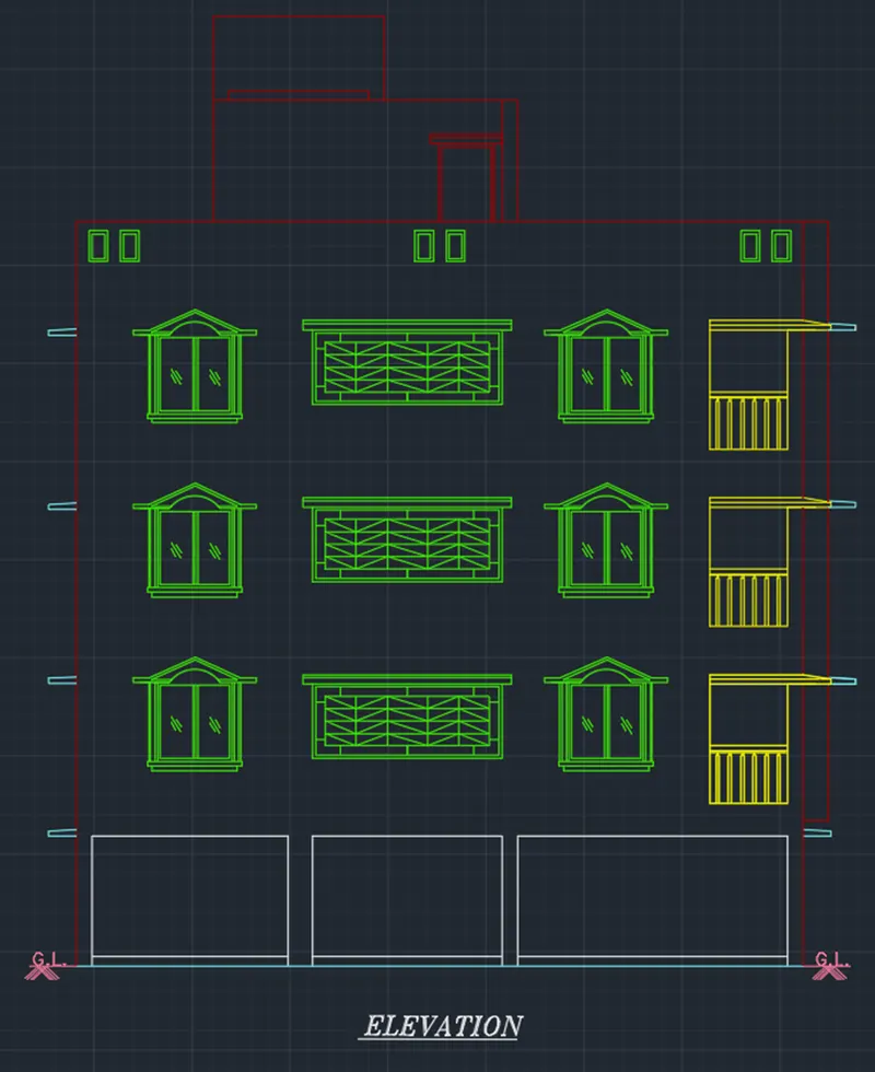
- With proper manipulation of the orthographic projections, you can easily plot the externals and window/ balcony separations of the Elevation Drawing.
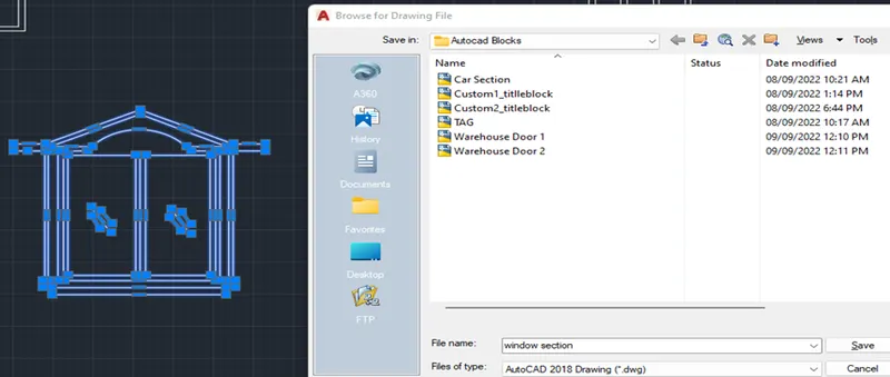
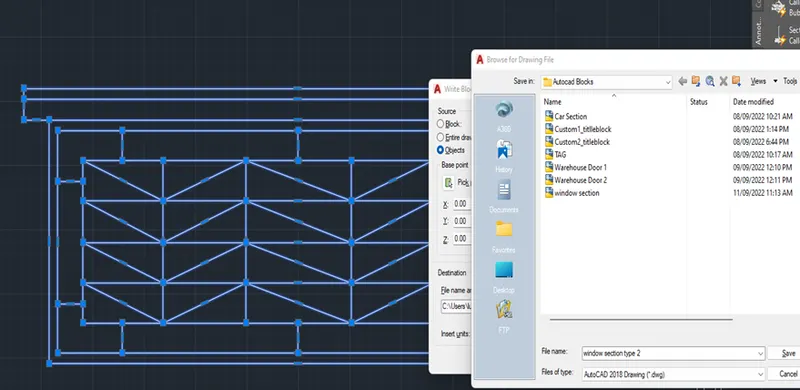
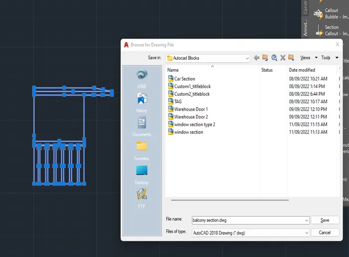
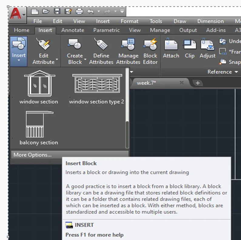
- Proceed with plotting the different types of window sections and the balcony. Saved it through WBLOCK so it can be useful for other drawings or projects.
- Insert the created blocks to its location established by orthographic projections and offset command based on the previous challenge 7 layout.
- Proceed with cleaning the drawing inline with the given sketches and with proper layering based on Challenge 7 layout.
Challenge 3: Below are the brief steps while working on the requested sketches.
- Set up the Units, Limits and Layers.
- Draw the Construction Line using XLINE, start from the bottom left.
- Construct the separations using the commands; offset, trim, fillet and erase as applicable while maintaining proper layering.
- Use the dimension given from the sketch provided and only assumptions as applicable.
- Plotting all the necessary geometries to proceed with proper hatching as applicable.
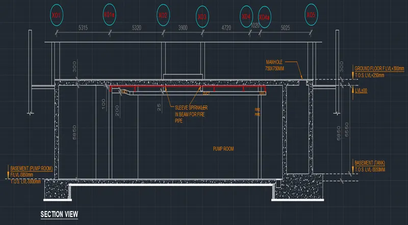
- Annotations to follow with the aid of Attributes as applocable.