Creating Kitchen layout, Hatching of Architectural elements and sectional view of an Industrial Building in AutoCad
CHALLENGE WEEK - 9
AutoCADD Essential
Question no.1:
- AIM:
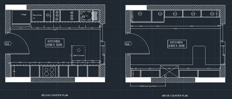
- To create the layouts of the Kitchen and provide hatches pattern
- To use text and dimensions.
- Procedure:
- Select the line tool.
- A rectangle of required size was drawn whicch is the otter line of the wall of a kitchen layout.
- The line is offsetted for 300mm to represent the wall of the kitchen layout plan.
- Then the door size is cut to draw a door and place.
- The door of required size was drawn with line tool and arc tool and made as block.
- The block was saved as door.
- Then the block was plced in the place were the wall lines are cut and provided with space.
- And another place was cut for the purpose of placing the window in the kitchen.
- The measured window size was drafted using line tool.
- Then the drafted window was place to the specified position.
- Then the components of the kitchen are drafted according to the kitchen spaces.
- Then measurements of the components are marked with the required dimensions lines.
- The components are made as blocks and placced in required places.
- The measurement for all the lines and components are marked perfectly.
- Then teh walls are to be hatched as per requirement.
- The cut plan view is hatched accordingly.
- The coreplaces are hatched with solid hatch and the wall cut is hatched with cross lines.
- The proper texts are marked and represented.
- The lines are drafted and shown perfectly with correct line scale and lien types.
- The wall lines are marked with solid lines.
- Thus the required kitchen layout was drafted with all requirements and specifications.
- RESULT:
- Thus the required kitchen layout was drafted with all requirements and specifications.
- The drawing contains the texts and dimension of required sizes.
Question no.2:
- AIM:
- To create the elevation of the plan as mentioned
- To use proper dimensions and hatches.
- Procedure:
- Select the line tool.
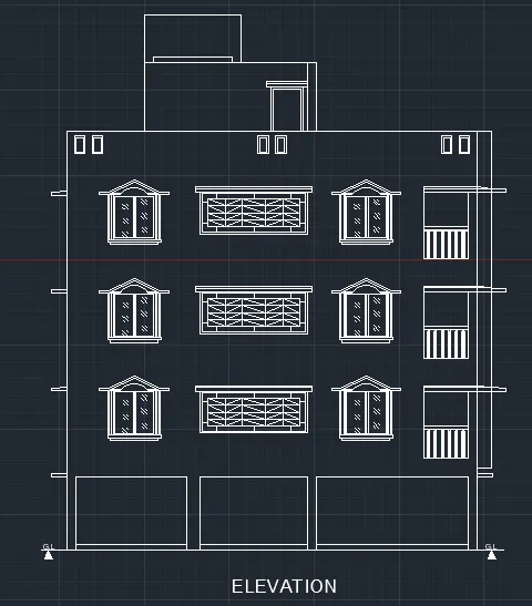
- The elevation of the plan was drafted using line tool.
- This elevation was drafted by using predrawn plan of a residential building.
- The outter sketch of the elevation was sketched with the reference of the residential plan.
- The elevation contains windows and balconies.
- The window was drafted with required dimesions.
- Then the window was made as a block.
- The window also contains hatch of a galss.
- The window thus formed as block was named as the elevation window of style 1.
- Then the drafted window was then copied to required places.
- The The elevation also contains certain designs in the elevation.
- The design was drafted with line tool.
- Then th same was made as block and the block was named as elevation design.
- Then such design was copies to required places.
- Then two rectangle of the elevation was drafted as design.
- Then the rectangle was made as block.
- The block was named as elovation rectangle design.
- The block was then copied to the required positions.
- Then the balconies were drafted.
- The head room of the building was drafted in the elevation.
- Thus the required elevation of the residential plan was drafted.
- RESULT:
- Thus the required elevation of the residential plan was drafted.
- The drawing contains the texts and dimension of required sizes.
Question no.3:
- AIM:
- To create the section view of an industrial building
- To use proper dimensions and hatches.
- Procedure:
- Select the line tool.
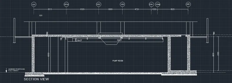
- The drawing is about the section of a industrial building.
- The section is cut such that it shows the pump room of the industrial building.
- The section is drawn with grid lines.
- The sections shows the cut of the wall.
- The walls are hatched with concrete hatch.
- Then the below of the wall is hatched with the solid hatch.
- Then the wall sizes are marked with dimesions
- The size of the cut room is marked.
- The duct lines are drafted in the section.
- The dimensions are marked with the reference of the grid line.
- The lines are offseted to form the wall of the industrial line.
- The manhole for the pump room is marked in the corner and shown in the section.
- Thus the required section of the pump house of an industrial building is drafted properly.
- RESULT:
- Thus the required section of the pump house of an industrial building is drafted properly.
- The drawing contains the texts and dimension of required sizes.