Creating Kitchen layout, Hatching of Architectural elements and sectional view of an Industrial Building in AutoCad
Q1,
AIM:
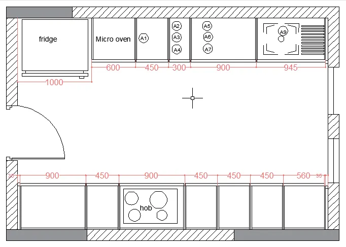
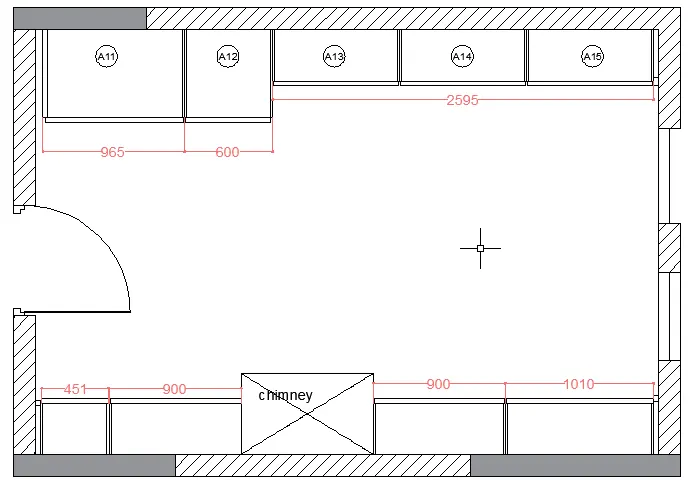
To create the layouts of the Kitchen and provide hatches pattern as shown and provide the dimensions in the plan. By assuming the size of doors, appliances and others as per the standards.
PROCEDURE:
Using the XL tool the left side corner of the plan is marked taking that as the starting point offset the thickness of the wall as 300mm and from the offset the room size.
like same way the cabinets and the other appliances are drawn.
RESULT AND REPORT:
With the help of XL, line offset, trim tool the plan shown in the figure is drawn.
-----------------------------------------------------------------------------------------------
Q2,
AIM:
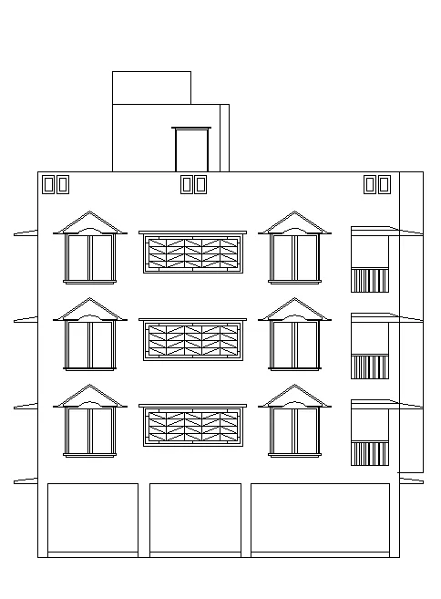
To create the elevation of the plan created in the challenges 7 and apply proper hatch in the walls, doors, windows, and other architectural elements.By refering the dimensions in Plans and sections in challenges 7.
PROCEDURE:
With refering the section of challenge7, using the line, offset tool, rectangle tool, copy, move, mirror the shown figure is drawn.
REPORT AND RESULT:
------------------------------------------------------------------------------------------
Q3,
AIM:
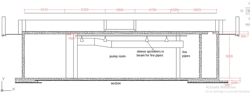
To create the section view of an industrial building as shown in Figure.And provide the appropriate hatches and dimensions.
PROCEDURE:
As the dimesions are mentioned on the figure, mark the starting point of the section plan is marked.
And the dimesions are followed by offseting them.
But the walls are to be in a closed loop so it should be hatched with the concrete hatch.
And the dimensions are mentioned with the help of the dim linear tool.
RESULT AND REPORT:
-----------------------------------------------------------------------------------------------