Creating Kitchen layout, Hatching of Architectural elements and sectional view of an Industrial Building in AutoCad
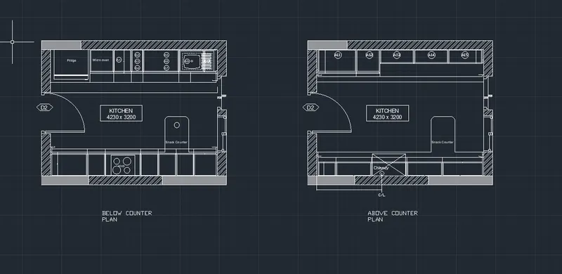
1.Create the layouts of the Kitchen and provide hatches pattern as shown. Also, use blocks wherever required. Provide appropriate dimensions in the plan. Assume the size of doors, appliances and others as per the standards.
Ans:
AIM: To create the layouts of the Kitchen and provide hatches pattern as shown in given figure using various drawing tools in AutoCad. Creating blocks and using wherever required. Providing dimensions in the plans.
PROCEDURE:
- The kitchen plan already created in previous challenges is used for this challenge.
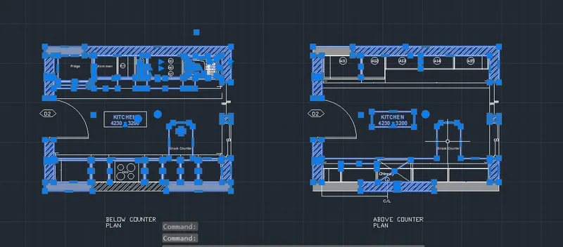
- The plans are separated by removing all the furniture
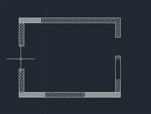
- Only the walls and columns of the kitchen is ready.
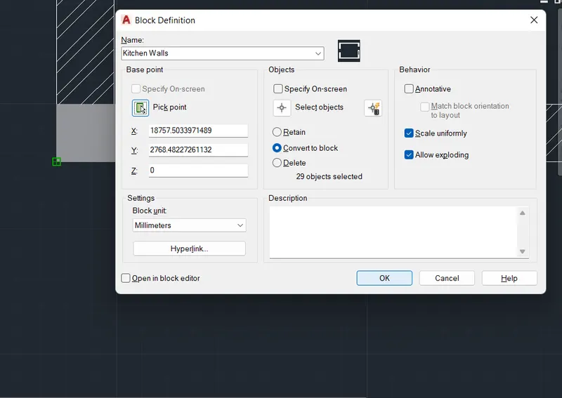
- Block is created for the walls and columns of kitchen plan
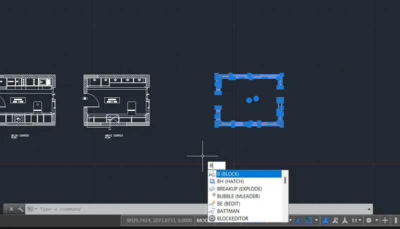
- The pick points are selected and the block is named as kitchen walls
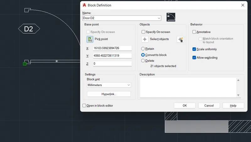
- The block is created for the door.
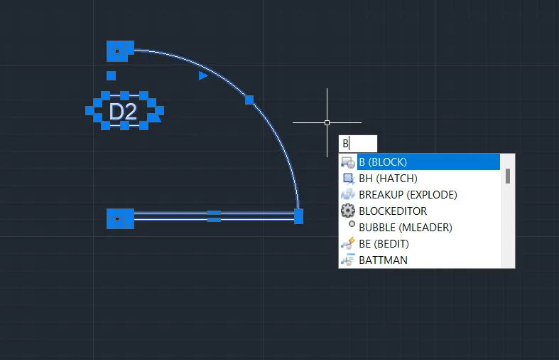
- The block is named for door
- The block is created for Fridge.
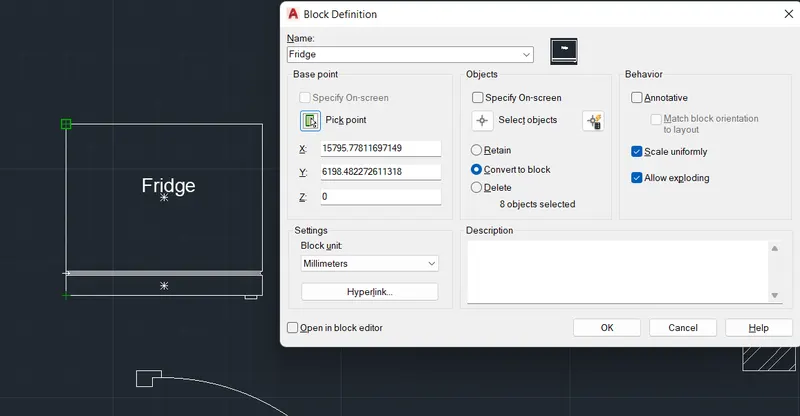
- Block for Fridge is ready and same can be used in the drawing by using insert command.
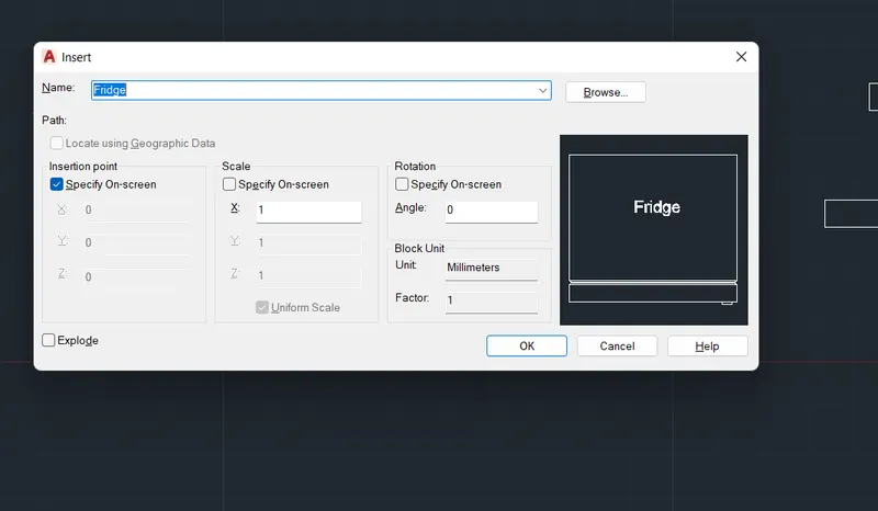
- The list of the blocks created will be popped up when insert command is entered.
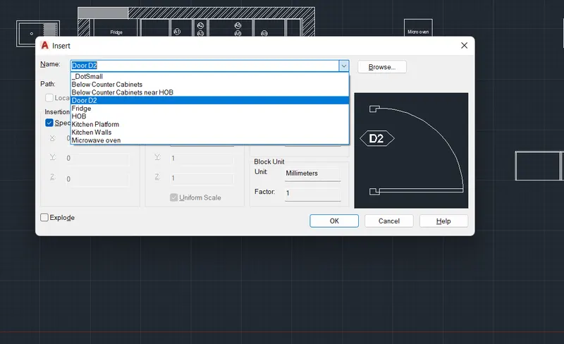
- Thus the blocks are created separately for all the furniture and equipments.
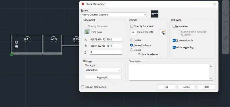
- Block creation for the above counter cabinets
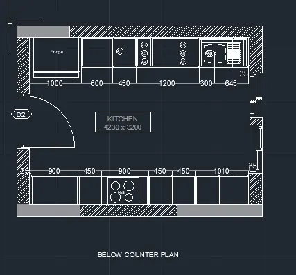
- Necessary labeling and naming is done as per given drawing and the dimensions are also provided.
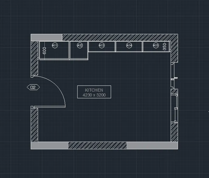
- Thus final kitchen plans are prepared as shown below with all the required details.
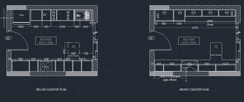
CONCLUSION: Thus we have prepared the kitchen layout plans using various drafting tools in Autocad. The required hatch patterns area provided and blocks area created for all the items. Dimensions and texts area provided as required.
2. Create the elevation of the plan created in the Challenges 7 and apply proper hatch in the walls, doors, windows, and other architectural elements. Refer to the dimensions in Plans and sections in Challenges 7.
Ans 2:
AIM: To create the elevation of the plan of building created in challenge 7 and providing the required hatch in walls doors as shown in the drawing.
PROCEDURE:
- The plan and section drawings are copied from Challenge 7 in the new drawing.
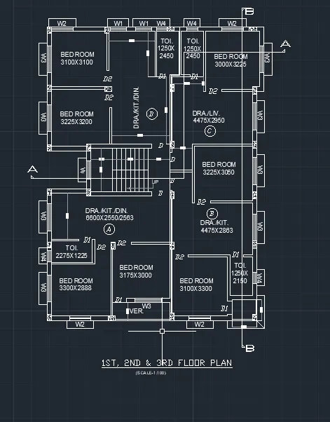
- The rays are drawng from the required side of plan for creating elevation drawing.
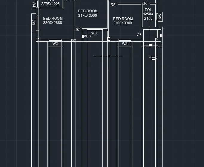
- Horizontal base line for ground level is drawing.
- The horzontal lines for various levels of floor as per given elevation are drawn
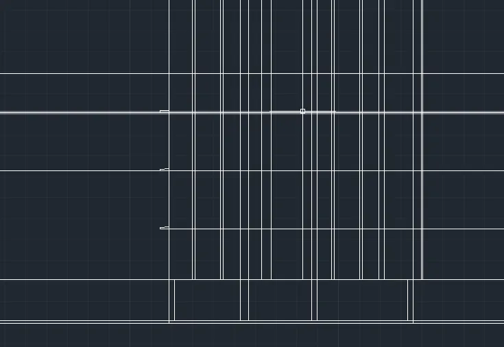
- The unwanted lines are trimme off.
- The sunshades are drawn at require levels
- Window is drawn as per the given elevation using various tools like line, offset, trim, extend, arc etc.
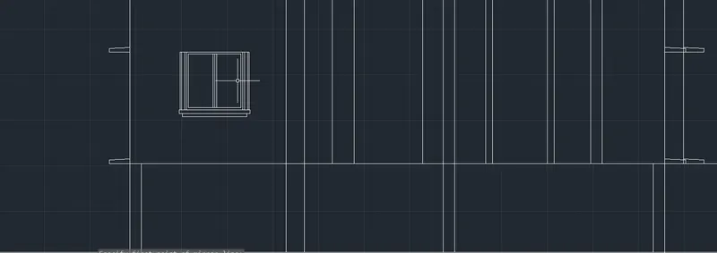
- The window drawing is completed
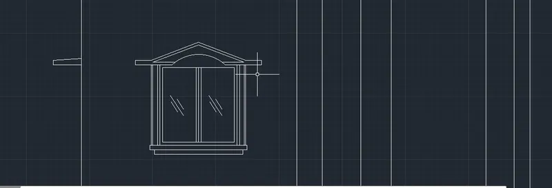
- Block is created for the window so that it can be easily used for repeating the windows where required.
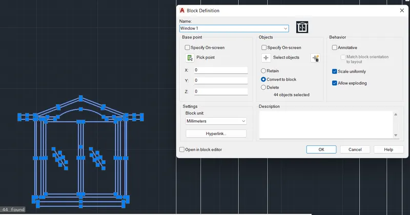
- Similarly the other type of window is also drawin with the given design and block is created as window 2 for using at different levels as shown in the drawing.
- The balcony railings are created and repeated for different levels.
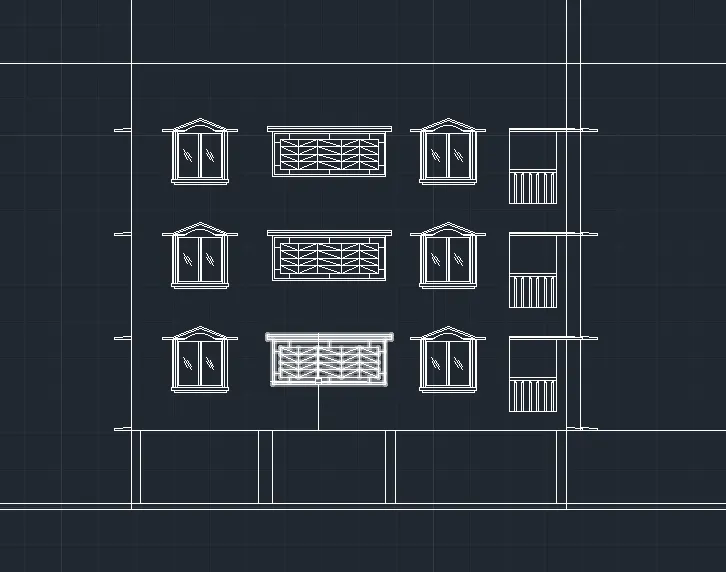
- The water tank and headroom elevation and elevational features area created.
- The drawing name with required font is provided
- Thus the completed drawing is shown below
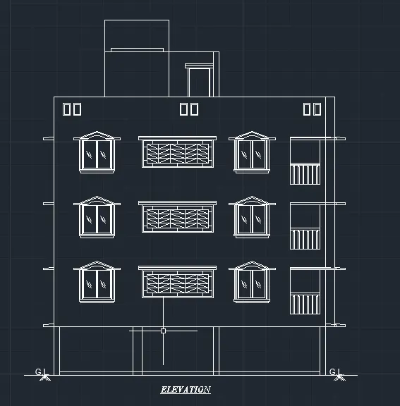
CONCLUSION: Thus we have created the elevation drawing for the building plan from Challenge 7 by using various drawing tools in AutoCad. The screenshots for the procedure are attached for reference .
3. Create the section view of an industrial building as shown in Figure. Provide appropriate hatches and dimensions wherever required. Also, provide annotations to the drawing.
Ans 3:
AIM: To create the section view of an industrial building as given in the figure. To provide hatches and dimensions where required along with the given annotations.
PROCEDURE:
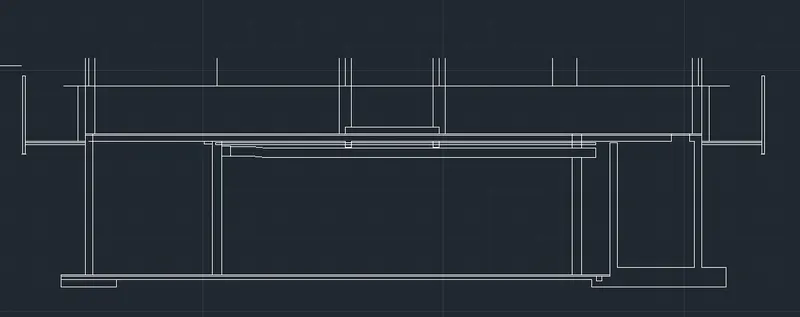
- Draw the center lines for the walls as given in the figure.
- Horizontal lines are provided as per the given heights and levels.
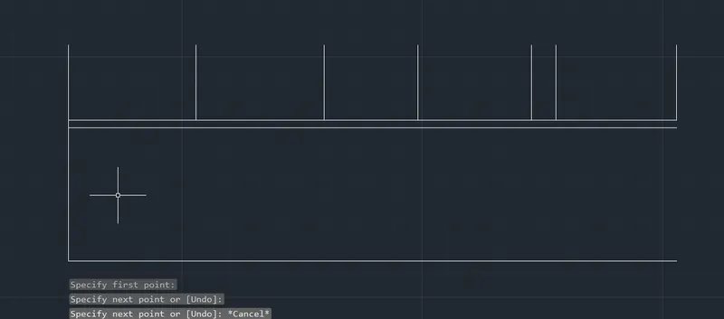
- With reference to the center line the wall thickness are provided by offset command by assuming the appropriate sizes
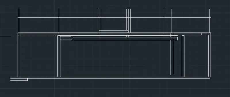
- The services of duct and firefighting pipe are drawn as per given figure.
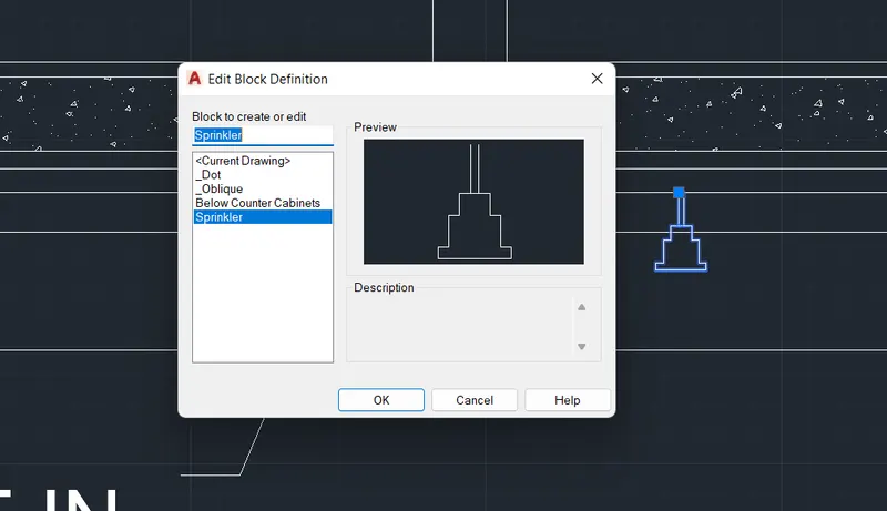
- The sprinkler are drawn and block is created for the easy repetitive use.
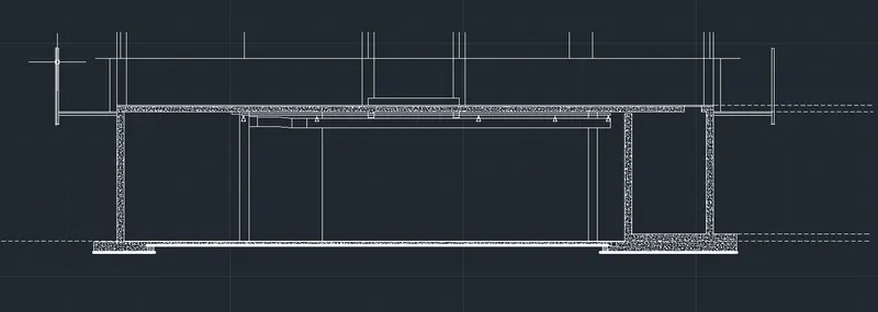
- Hatch is provided for the concrete structure.
- The center line numbering is created , the line types are changed as dotted and center line as per given figure.
- Using the express tools the center line numbers are encircled.
- The annotations are provided for levels and details.
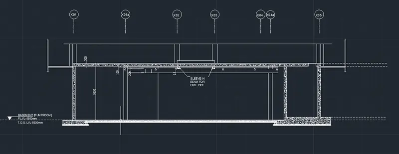
- Thus final drawing of industrial building drawn is shown below in the attached screenshot.
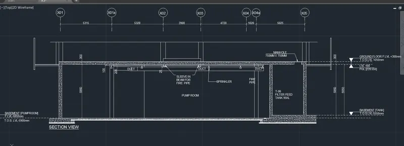
CONCLUSION: Thus with help various drawing tools in AutoCad we have drawn the section view of the industrial building provided in the figure. The dimensions and text details are also provided and the linetypes are selected appropriately.