Creating Kitchen layout, Hatching of Architectural elements and sectional view of an Industrial Building in AutoCad
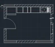
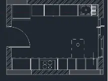
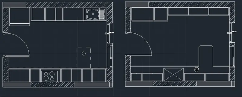
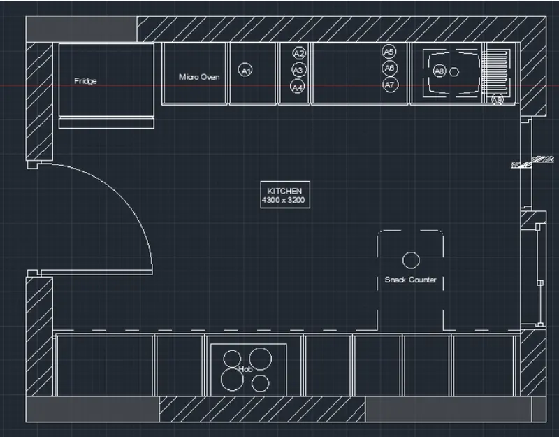
Create the layouts of the Kitchen and provide hatches pattern as shown. Also, use blocks wherever required. Provide appropriate dimensions in the plan. Assume the size of doors, appliances and others as per the standards.
Aim:
To Create the Kitchen Layout and to Also, use proper dimension techniques to dimension the kitchen layout. Also, insert text wherever required. All dimensions are in mm.
introduction: AutoCAD consists of a number of drawing and modification tools. Among the modification tools are chamfer, fillet,offset,object snap, rotate,copy,move,mirror,trim, entend and join Chamfer: A chamfer is an angled line that meets the endpoints of two straight 2D objects its a sloped transition between two surfaces or adjacent faces on a 3D solid. We type CHA for this tool in command bar
drafting a following tools by using following commands like, by using object snap elliptical command, by using arcs commands construction lines and ray tools, divide and measure tool, and by Using modity commands like mirror, trim, entand explode, lenghten, align, break and join command, and manage layers in autoCAD 2019
Procedure:
step 1:
units are set to mm
limits and limax are also set zoom comand is also used
Step 2:
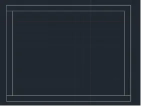
In the command prompt type rec and the dimensions are 4734 x 3688 mm
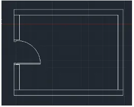
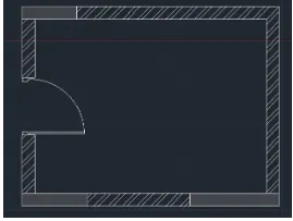
Using arc and lines the door is drawn In the command prompt type hatch to hatch the model
the fridge
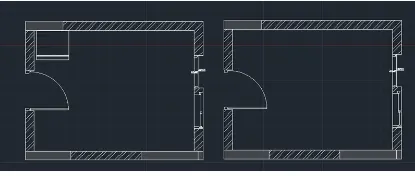
In the command prompt type offset and offset it to the distance of 230mm In the command prompt type rec › dimensions, to do In the command prompt type offset and offset it to the horizontal distance of 350,450,900,450,450 and 560 In the command prompt type trim to trim the extras In the command prompt type line type and load the
desired distace to get the Micro Oven In the command prompt type trim to trim the extras
In the command prompt type offset and offset it to the
In the command prompt type offset and offset it to the vertical distance of 600
dotted lines
In the command prompt type text to text the given
annotations
In the command prompt type dimensions to given the
dimensions to your plan In the command prompt even the leader command is
used to name the dimensions
Final Result:
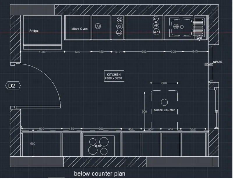
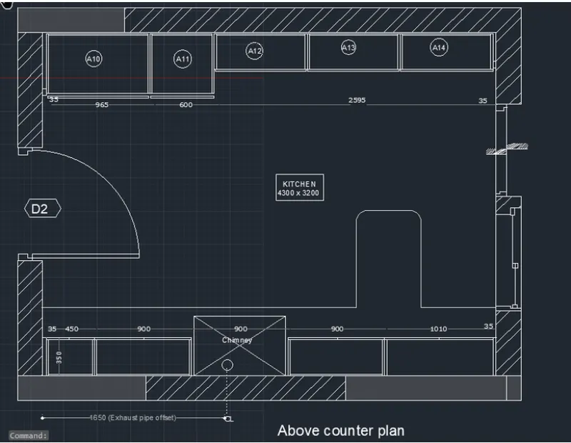
2. Create the elevation of the plan created the Challenges 7 and apply proper hatch in the walls, doors, windows, and other architectural elements. Refer to the dimensions in Plans and sections in Challenges 7. Refer to the elevation that needed to be created.
AIM:
To create the elevation of the plan with hatch
PROCEDURE:
• In the command prompt type to draw the lines
• In the command prompt type rec to draw the rectangle • In the command prompt type arc to draw the arc
Therefore, the window is created
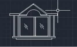
In the command prompt type I to draw the lines
In the command prompt type rec to draw the rectangle
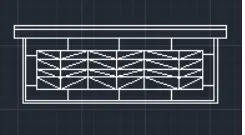
In the command prompt type to draw the lines
In the command prompt type rec to draw the rectangle
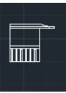
In the command prompt type rec to draw the rectangles
In the Ribbon bar
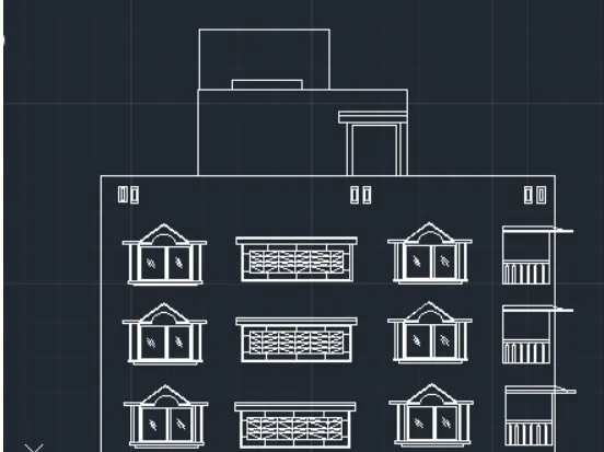
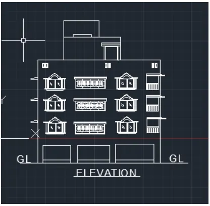
Final result
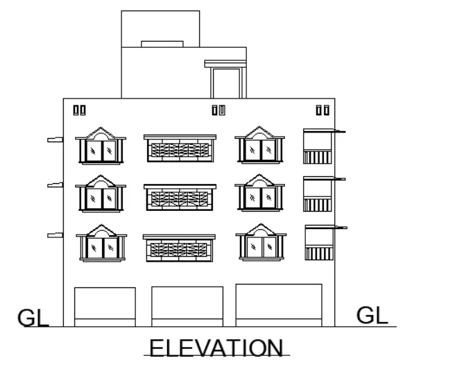
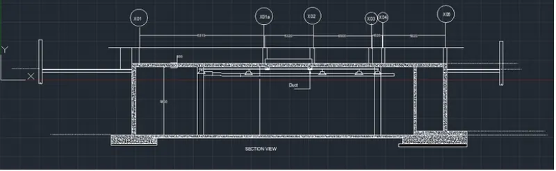
3. Create the section view of an industrial building as shown in Figure. Provide appropriate hatches and dimensions wherever required. Also, provide annotations to the drawing.
AIM:
To create the section view of an industrial building.
PROCEDURE:
In the command prompt type to draw the lines.
• In the Ribbon bar > Hatch > AR.CONC.
In the command prompt type rec to draw the rectangle.
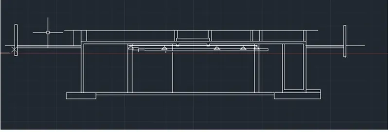
• In the Ribbon bar > Hatch > AR.CONC.
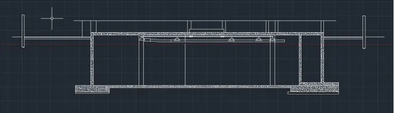
In the command prompt type LT to get the dotted lines In the command prompt type c to draw the circle
In the command prompt type Mt to draft the text
In the command prompt type dim to draft the
dimensions
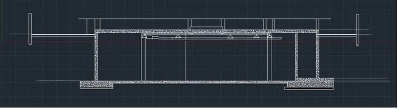
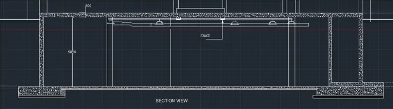
Final Result:
conclusion:
ALL RESULT OF EACH DRAWING HAS BEEN ATTACHED WHICH WAS TAKEN FROM AUTOCAD