Creating Kitchen layout, Hatching of Architectural elements and sectional view of an Industrial Building in AutoCad
Aim:
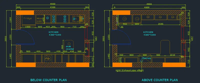
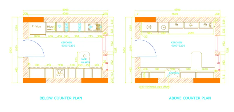
To create layouts of kitchen and provide hatches as shown. Use blocks and also provide dimensions to the plan.
Procedure:
- using rectangle tools create the rectangle of size 4300*3200mm and offset the rectangle at a distance of 300mm in the outer side.
- By using trim and fillet tool, trim the unwanted lines and Then explode the rectangles.
- Place the door of size 1050mm and window of size 932mm of two windows.
- Make the copy of the created kitchen.
- Then offset the left side wall line to the following distances 1000mm, 600mm, 450mm, 300mm, 900mm, 35mm respectively.
- Offset the upper wall line at a distance of 600mm then using the fillet and trim command create the fridge, oven and others.
- Then offset the bottom line at a distance of 600mm.
- Offset the left side wall line the following distances 35mm,900mm, 450mm, 450mm, 450mm, 560mm and 35mm.
- Then using the trim tool, trim the unwanted lines to create the bottom snak counter and others.
- Ofset the another kitchen left side wall at a distance of 35mm, 965mm, 600mm, 2595mm respectively.
- Offset the upper wall line at a distances of 350mm and 600mm.
- Then by using trim tool, trim the unwanted lines.
- Then by using the same procedure create the bottom furnitures.
- Create all the appliances as a block.
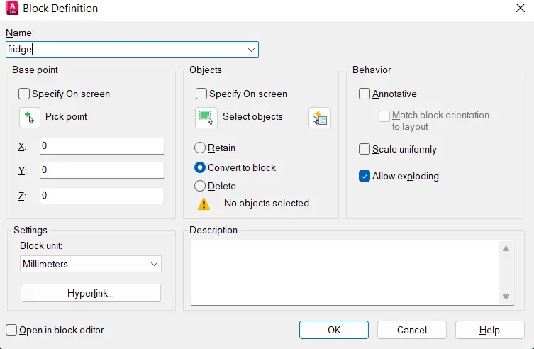
- Use This method to create all other appliances as a block.
- Hatch the walls.
- By using hatch tool, typing 'H' in command prompt.
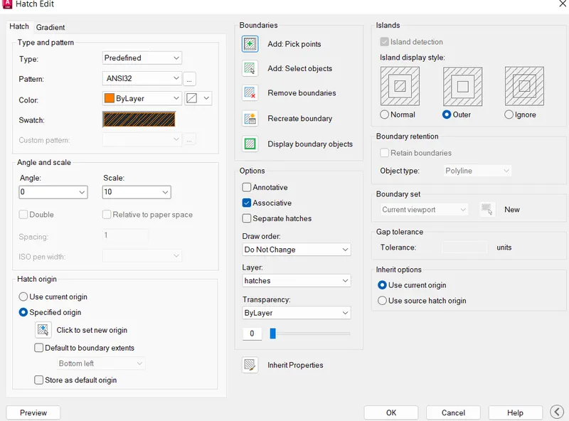
- Open the settings and choose the predefined.
- Choose ANSI32 pattern and scale 10.
- Pick the wall as a hatch point.
- By using text tool, create texts to a required places and dimension using the continuous technique.
- Create New layers by open the layers property manager.
- Create layers by the names as wall, doors, windows, hatches, appliances, dimensions and annotations.
- Put each components in the specified layer.
Result:
The layouts of kitchen is created and hatches are provied as shown. Blocks are used and dimensions are also provided.
Aim:
To create the elevation of the plan created in challenge 7 and provide hatches to the walls, doors, windows and other architectural elements.
Procedure:
- Using external reference 'Xref' the challenge 7 plan.dwg
- Scale as uniform scale, path type 'Relative' and reference type as 'attachement'
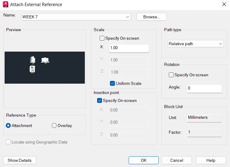
- After xref the .dwg file then bind it
- Explode the block by using explode tool. Now we can edit this drawing.
- Create construction lines in the edges of the plan
- Create a horizontal construction line in the bottom of section B-B
- Create a reference lines of doors and windows by using construction line horizontal in the section B-B
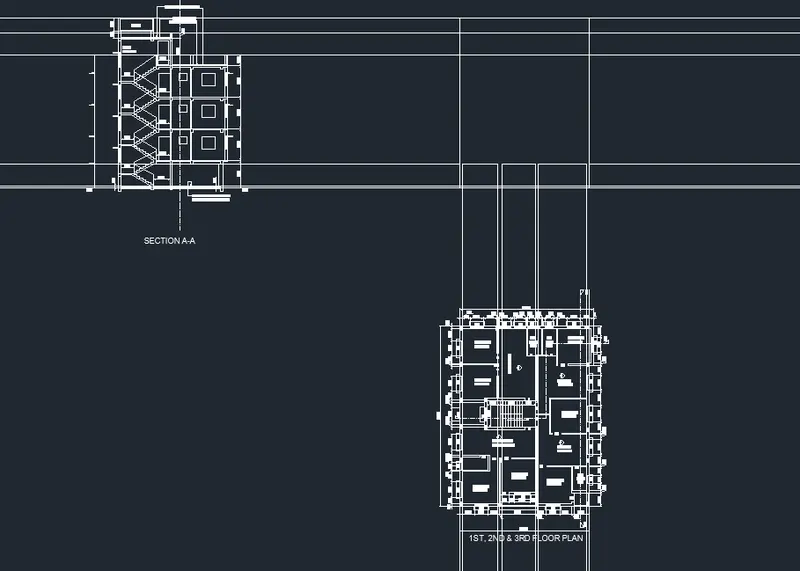
- Create windows, sunshade, bolcony area and doors in the necessary areas on the elevation.
- Using rectangle, line, circle and offset tools.
- To create the windows and doors frames and the other components.
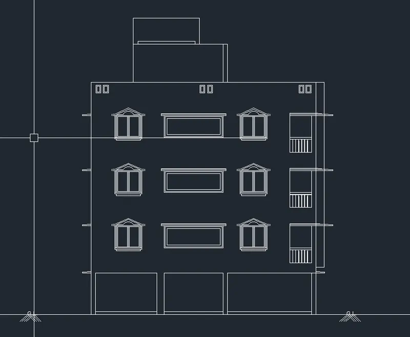
- Using hatch tool to the the door, windows and walls.
- The floor area as concrete.
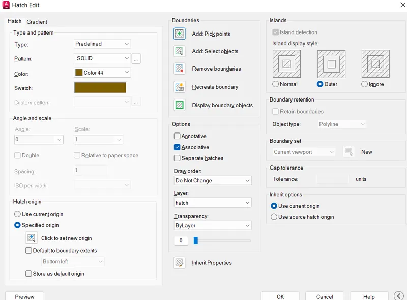
- Hatch the windows frame as solid pattern and color 44
- Use this method to hatch the other elements in the elevation.
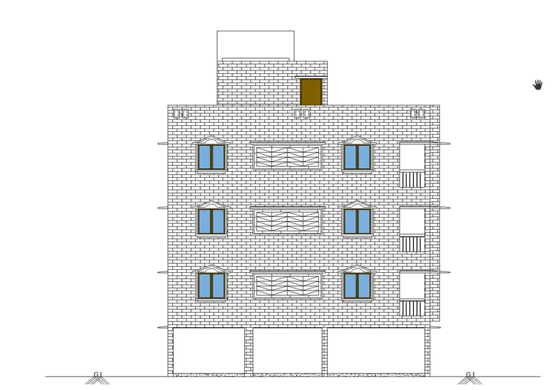
Result:
The elevation is created of the plan in challenge 7 and hatches are provided to the walls, doors, windows and other architectural elements.
Aim:
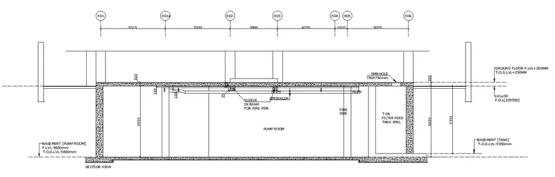
To create the section view of an industrial building as shown in figure and Provide hatches and dimenstons to the drawing.
Procedure:
- Open the Autocad and create new drawing.
- Create the drawing in metric and set the units as decimal and precision as 0
- Create the horizontal and vertical construction lines.
- Offset the horizontal construction line at a distance of 5850mm and 6150mm.
- Create a line at the right top corner and offset it at a distance of 400mm.
- Offset the last offseted line at a distances of 5315mm, 5320mm, 3900mm, 4720mm, 1020mm and 5025mm.
- Offset the created lines at a distance of 400mm in both the right and left side.
- Offset the left side line at a distance of 600mm and 2500mm and at a distance of 600mm. The filter feed is created.
- create a pump room by offseting the filter feed wall line at a distance of 9500mm.
- Create the footings by using rectangle and explode tools.
- Create the sprinkler pipe line and the sprinkler at the distance of 25mm from the bottom of the slab.
- Create a duct pipe below the sprinkler pipe line.
- Hatch the drwaing by typing 'H' in the command line.
- Open the hatch settings.
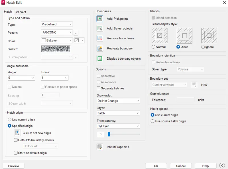
- Select the type as 'predefined', pattern as 'AR-CONC' and scale value as 1
- To hatch the walls and basement of the section.
- Use this hatch method to hatch the other elements in the sectional drawing.
- Use dimension linear command to dimension the sectional drawing.
- Type 'MT' in command prompt to annotate the drawing.
- Create leaders at the basement and the ground floor level and sleve in beam for fire pipe.
Result:
The section view of an industrial building as shown in figure is created and hatches, dimensions are provided to this drawing.