Creating Kitchen layout, Hatching of Architectural elements and sectional view of an Industrial Building in AutoCad
ANSWERS:
AIM: To create the Kitchen Layout of above counter and below counter plan with the help of Line, Rectangle, offset, Trim, extend, Xline command as shown in the figure above in AutoCAD.
INTRODUCTION: The desired Archetectural PLAN, Layout, Dimension is created in AutoCAD using primarily the Line tool, XLINE, Offset The procedure of drawing is explained in detail with diagrams of each step and the final result is given.
PROCEDURE:
Go to START MENU, select AutoCAD 2022.
In the Command line type in: STARTUP ,
Enter new value of start-up: 1
Go to Application Menu and select New
In the 'Create New Drawing' dialog box, we do the Advanced Setup and select the DECIMAL unit of measurement and select precision as 0.0
Set the limits by entering LIMITS in the Command tab. The lower-left corner is specified as 0,0 and the upper-right corner is specified as 10000,10000
Enter 'UNITS' command in the command tab.
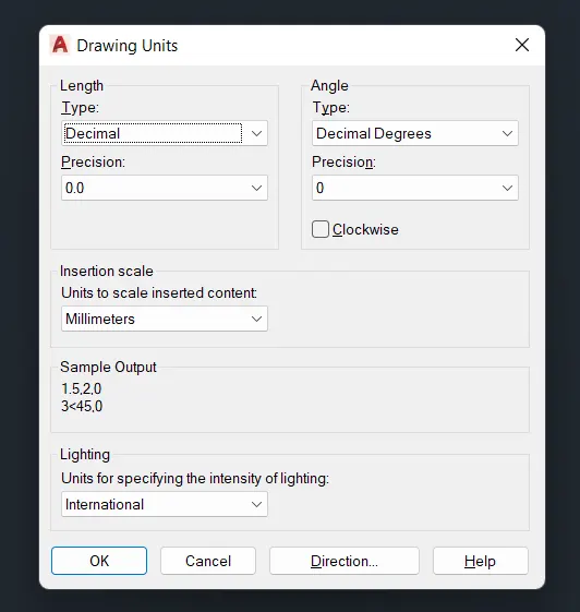
In the Drawing Units dialog box, select DECIMAL in Type 0.0 in Precision and MILLIMETERS in Insertion scale.
Click on 'OK'.
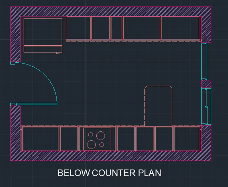
BELOW COUNTER PLAN
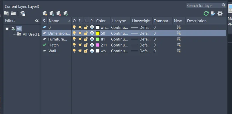
LAYER: Create LAYERS and Specify Respective Colour and Properties
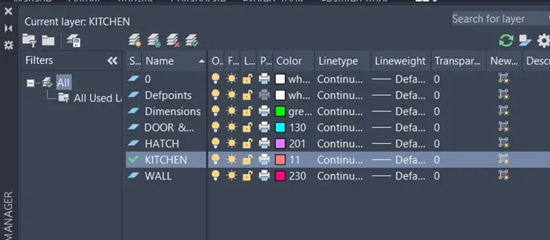
LAYER: KITCHEN
RECTANGLE: Create Rectangle of size 4300 x3200
OFFSET: Specify offset of 230, Click on the outside to offset

EXPLODE : Select the Interior Rectangle and Explode it
LINE: Specify the start point and Draw a line joining the inner edges of the kitchen wall
OFFSET : Line type -ISODASH ,Create an OFFSET at a Distance of 600 from baseline
RECTANGLE : Specify the First point as the left Corner below the osset line, Create 35x65
COPY : Copy the paste it in opposite end
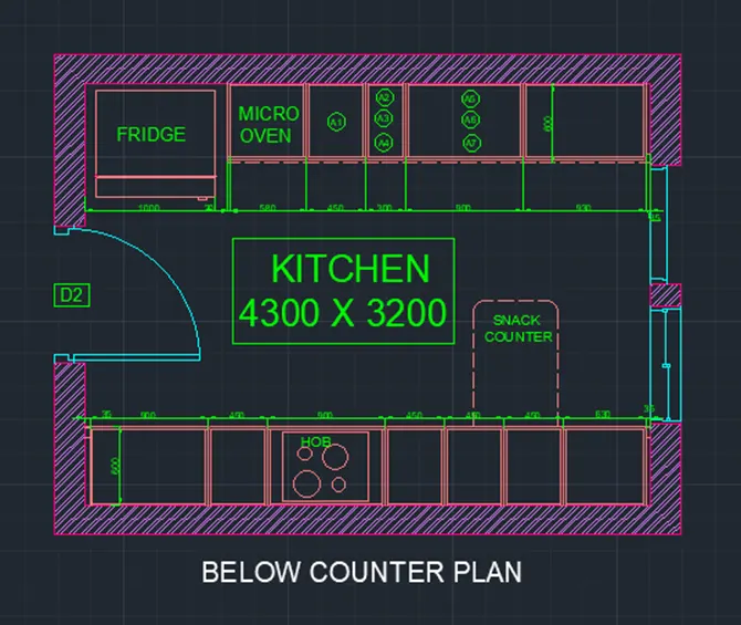
OFFSET: OFFSET the lines at a distance of 630,450,450,450, 900,450,900 as Centerline, Specify offseof 20 mm and Create offset on both sides of Centerline
OFFSET: now create an offset of 10mm from baseline at each and every interior Rectangle
Create same plan on opposite side of wall
LINE: Specify the start point and Draw a line joining the inner edges of the kitchen wall
OFFSET : Line type -ISODASH ,Create an OFFSET at a Distance of 600 from baseline
RECTANGLE : Specify the First point as the left Corner below the osset line, Create 35x65
COPY : Copy the paste it in opposite end
OFFSET: OFFSET the lines at a distance of 930,900,300,450, 580 as Centerline, Specify offseof 20 mm and Create offset on both sides of Centerline
OFFSET: now create an offset of 10mm from baseline at each and every interior Rectangle
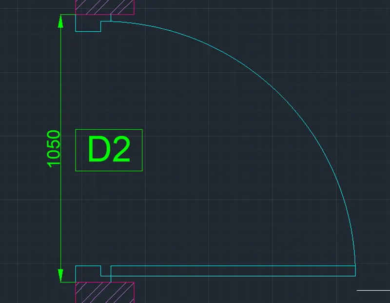
DOOR
LINE: Create Frame by 35 mm in Positive X Direction, 130 in Negative Y direction, 15 in Negative X Direction, 100 in Negative Y direction, 20 in Negative X direction and connect to wall,
RECTANGLE: Create Rectangle of Width 25mm Length 1010 (Deducting 20mm at Both end of Frame width) to Create Door
CIRCLE: Select 3 Point Circle and Specify the Centre point as one end of Frame and End Point as another End of Frame Click ENTER
TRIM: Erase all Unwanted parts of the Circle
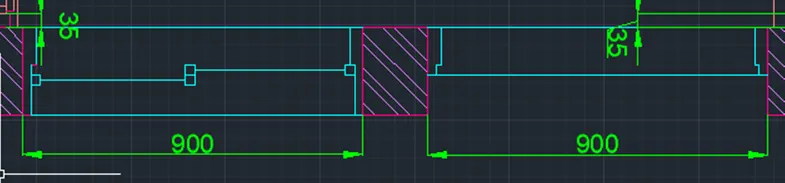
WINDOW
LINE: Create Frame by 35 mm in Positive X Direction, 130 in Negative Y direction, 15 in Negative X Direction, 100 in Negative Y direction, 20 in Negative X direction and connect to wall,
Create a Rectangle of 45X45 & Place it at the Centre
Copy and Mirror the Object, place it at a Distance of 900, and Connect the Line Between Rectangles
FURNITURES
LAYER :FURNITURES
DESIGN CENTER: TYPE DESIGN CENTER or Go to Insert tab, Insert Blocks, Insert Block From Libraries
Select the Desired Utility and Place it at the Right Location
LINE : select ISO02W100 to Create Dashed Line as per the Plan
LAYER: Dimensions
DIMLENIAR: Select and Place the Desired Dimensions, Represent all the Dimensions
DIMSTY: Set Arrow size 100, Text Height 250, Precision to 0
DIMCONTINUE: Create Remaining Dimensions
MTEXT: Create a Text Box and Enter the sample text, Copy and Paste multiple in Desired Position and desired angle with Desired Size
EDIT TEXT (ED): Edit the MTEXT Created and Pasted and Type the actual name, size, rotation angle
HATCH:
LAYER: HATCH
Select the ANSI32 to Represent the BRICK WALL
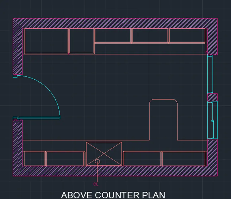
ABOVE COUNTER PLAN :
LAYER: KITCHEN
RECTANGLE: Create Rectangle of size 4300 x3200
OFFSET: Specify offset of 230, Click on the outside to offset
LINE: Specify the start point and draw a line joining the inner edges of the kitchen wall
OFFSET: Line type -ISODASH, Create an OFFSET at a Distance of 600 from baseline
EXPLODE: Select the Interior Rectangle and Explode it
OFFSET: offset 10mm from Both opposite ends from wall interior side
350mm from Baseline at Both Ends
RECTANGLE: Specify the First point as the left Corner below the ofsset line, Create 35x65
COPY: Copy the paste it in opposite end
OFFSET: OFFSET the lines at a distance of 20,1010,900, 900 ,900, 500,35 as Centreline,
Specify offset of 20 mm and Create offset on both sides of Centreline
LINE: Specify the start point and Draw a line joining the inner edges of the kitchen wall
OFFSET: Create an OFFSET at a Distance of 350 and 600 and from baseline on opposite side
RECTANGLE : Specify the First point as the left Corner below the offset line, Create 35x65
COPY : Copy the paste it in opposite end
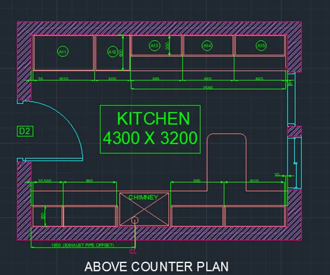
OFFSET: OFFSET the lines at a distance of 865,865,865(for 350 width ),600, 1035,35 as Centreline, Specify offset of 20 mm and Create offset on both sides of Centreline
Layer : Furniture
RECTANGLE : Specify first point at a distance of 1500 from Left inner Wall and Specify 800,500
LINE: Create the Diagonal Lines For Previously created Rectangle
TRIM : cut off all the unwanted lines intersecting , and lines extending beyond 350mm at right side of kitchen.
LAYER: Dimensions
DIMLENIAR: Select and Place the Desired Dimensions, Represent all the Dimensions
DIMSTY: Set Arrow size 100, Text Height 250, Precision to 0
DIMCONTINUE: Create Remaining Dimensions
MTEXT: Create a Text Box and Enter the sample text, Copy and Paste multiple in Desired Position and desired angle with Desired Size
EDIT TEXT (ED): Edit the MTEXT Created and Pasted and Type the actual name, size, rotation angle
HATCH:
LAYER: HATCH
Select the ANSI32 to Represent the BRICK WALL
RESULT:
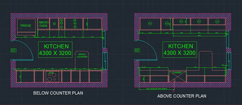
AIM: To create the Kitchen Layout of above counter and below counter plan with the help of Line, Rectangle, offset, Trim, extend, Xline command as shown in the figure above in AutoCAD.
INTRODUCTION: The desired Archetectural PLAN, Layout, Dimension is created in AutoCAD using primarily the Line tool, XLINE, Offset The procedure of drawing is explained in detail with diagrams of each step and the final result is given.
PROCEDURE:
Go to START MENU, select AutoCAD 2022.
In the Command line type in: STARTUP ,
Enter new value of start-up: 1
Go to Application Menu and select New
In the 'Create New Drawing' dialog box, we do the Advanced Setup and select the DECIMAL unit of measurement and select precision as 0.0
Set the limits by entering LIMITS in the Command tab. The lower-left corner is specified as 0,0 and the upper-right corner is specified as 10000,10000
Enter 'UNITS' command in the command tab.
In the Drawing Units dialog box, select DECIMAL in Type 0.0 in Precision and MILLIMETERS in Insertion scale.
Click on 'OK'.
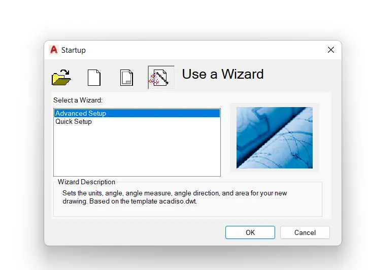
select the DECIMAL unit of measurement and select precision as 0.0
LAYER: Create LAYERS and Specify Respective Colour and Properties
XREF : Click on Attach DWG in the External reference Dialog box.
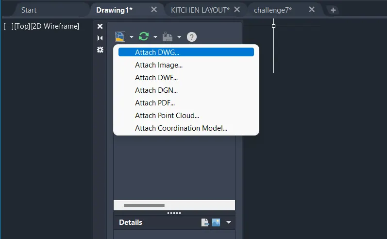
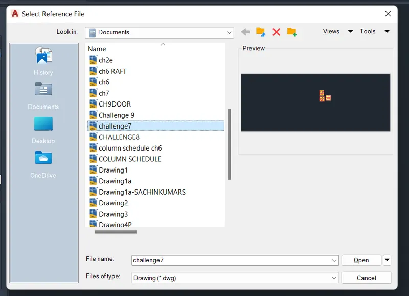
Select the Week 7 drawing "CHALLENGE 7".
External reference Dialog box, right click on the attached file.
Click on the Bind option and Select Insert.
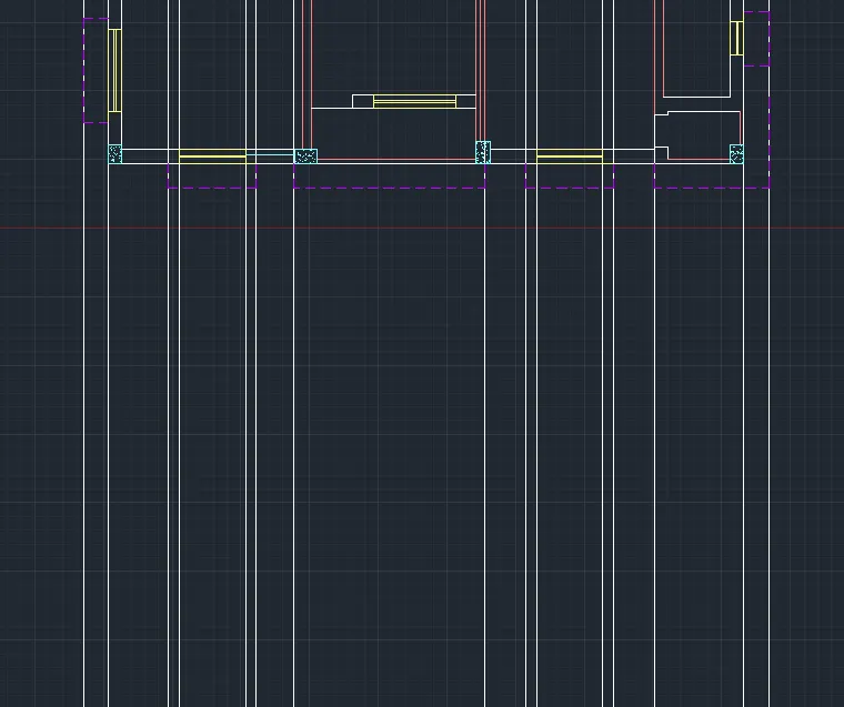
Xline: Project all the Lines from the Plan including all chajja, window as shown in figure
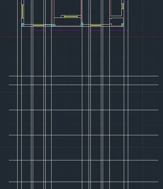
XLINE: from the Sectional elevation Project all the floor lines, tank, parapet wall as shown in figure
RECTANGLE: Create the Window in from the visible Rectangle
RECTANGLE: Also create the chajja from the projected lines
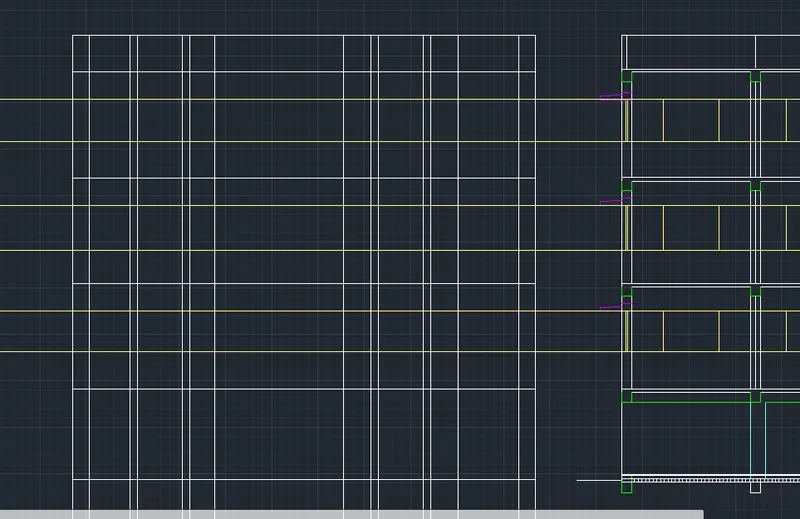
OFFSET:Specify offset distannce of 50 and create the frame of the window by offsetting the lines on all four sides.
LINE :Specify the start point.
Draw the top triangular portion of the window as shown in figure
ARC: Select the Arc tool from the ribbon, choose the Start, End, Direction option, then draw an arc at the top portion of the window.
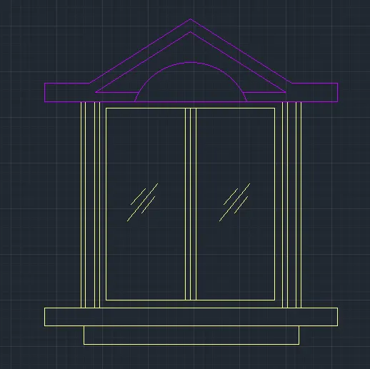
Line:Create the Balcony as shown in figure
To create a Verandah Grill
XLINE : Project the Vertical and Horizontal lines
RECTANGLE : Create the Rectangle of Window grill
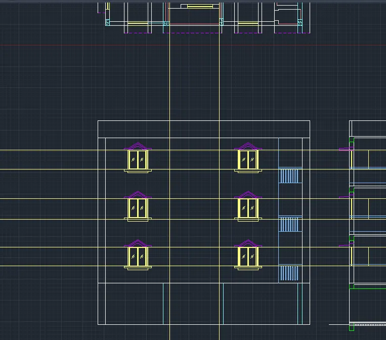
OFFSET : Specify an offset distance of 50 and click inside
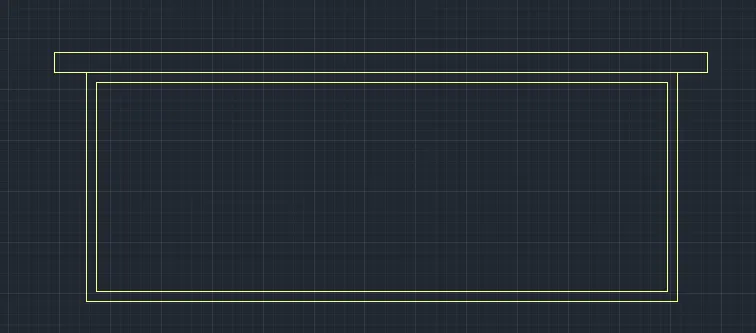
OFFSET : Specify an offset distance of 150 and click inside
DEVIDE: Select the left hand side line of the smaller rectancle and divide it into 4 sections
select the top side line of the smaller rectancle and divide it into 4 sections.
LINE: Create the Line from the devided points
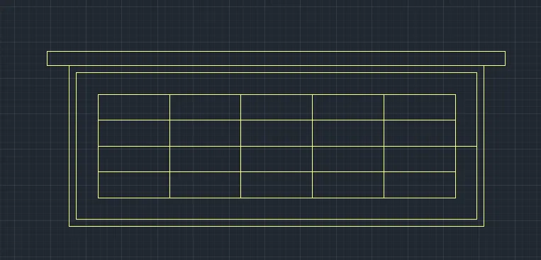
LINE : Connect the Points as shown in figure
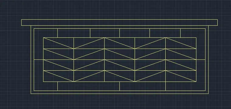
Copy: Select copy and paste the window to all desired Positions
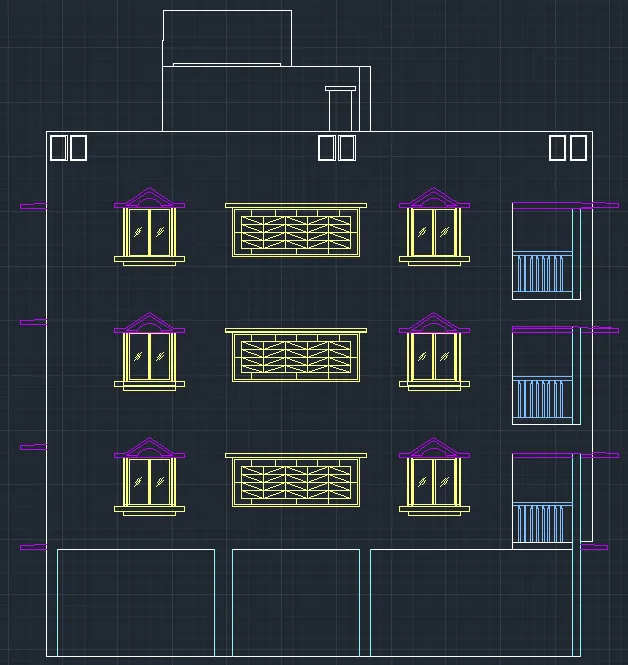
LAYER: Dimensions
DIMLENIAR: Select and Place the Desired Dimensions, Represent all the Dimensions
DIMSTY: Set Arrow size 25, Text Height 50, Precision to 0
DIMCONTINUE: Create Remaining Dimensions
MTEXT: Create a Text Box and Enter the sample text, Copy and Paste multiple in Desired Position and desired angle with Desired Size
EDIT TEXT (ED): Edit the MTEXT Created and Pasted and Type the actual name, size, rotation angle
RESULT :
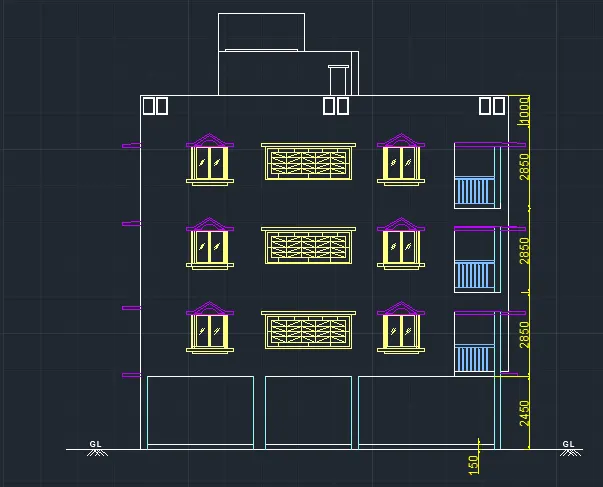
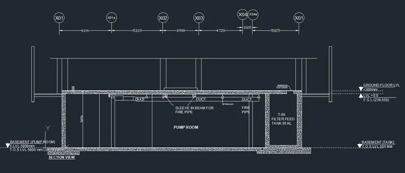
SECTIONAL VIEW OF INDUSTRIAL BUILDING
Aim: To draw the section view of an industrial building as shown in the figure above, in AutoCAD.
Introduction: The section is created in AutoCAD using primarily the Rectangle, Line, Offset and Trim tools, the dimensions and text are provided with the use of layers. The procedure of drawing is explained in detail with diagrams of each step and the final result is given.
Procedure :
Go to START MENU, select AutoCAD 2022.
In the Command line type in: STARTUP ,
Enter new value of start-up: 1
Go to Application Menu and select New
In the 'Create New Drawing' dialog box, we do the Advanced Setup and select the DECIMAL unit of measurement and select precision as 0.0
Set the limits by entering LIMITS in the Command tab. The lower-left corner is specified as 0,0 and the upper-right corner is specified as 10000,10000
Enter 'UNITS' command in the command tab.
In the Drawing Units dialog box, select DECIMAL in Type 0.0 in Precision and MILLIMETERS in Insertion scale.
Click on 'OK'.
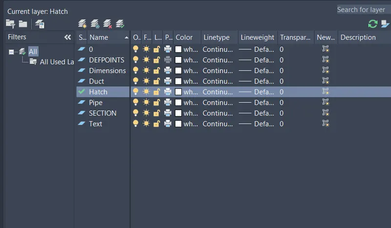
: 
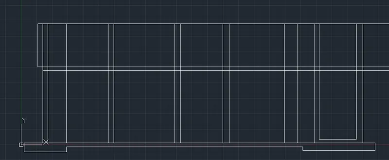
XLINE: Create a Horizontal and Vertical Xline
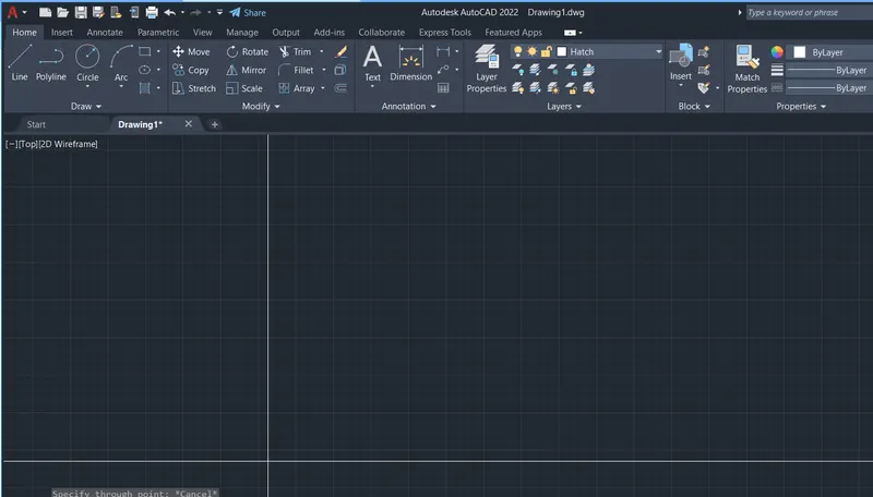
OFFSET : Specify an Offset of 5850 in Upward Direction
Specify an Offset of 300 from Previously offset line in downward direction
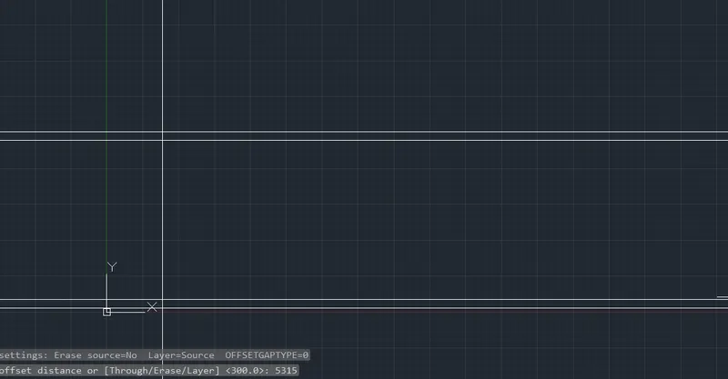
OFFSET : Similarly Specify offset distances of 5315 towards Right
Specify offset of 5320 towards Right from Preciously offseted Line
Specify offset of 3900 towards Right from Preciously offseted Line,
Specify offset of 4720 towards Right from Preciously offseted Line,
Specify offset of 1020 towards Right from Preciously offseted Line,
Specify offset of 5025 towards Right from Preciously offseted Line
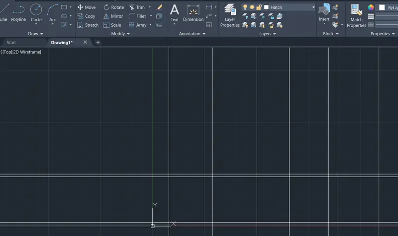
OFFSET : By Considering the Above offested lines as Reference Create the Wall Thickenesses on both side of the Line
Trim : Trim the reference line , cut off the unwanted lines
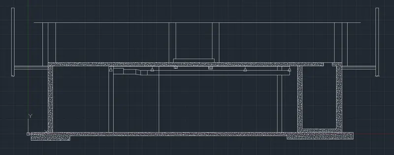
Rectangle : Create the Pipe on either side of the drawing by creating a Rectangle
Explode : Select and Explode the Rectangle
Express tools > Break line Symbol : Create the Breakline symbol on both the Pipes
Line : Crrate the Required lines on desired positions as shown in figure
Create the Duct Line and
HATCH : layer : Hatch, select AR-CONC, select the Boundary
LAYER: Dimensions and Text
DIMLENIAR: Select and Place the Desired Dimensions, Represent all the Dimensions
DIMSTY: Set Arrow size 25, Text Height 50, Precision to 0
DIMCONTINUE: Create Remaining Dimensions
MTEXT: Create a Text Box and Enter the sample text, Copy and Paste multiple in Desired Position and desired angle with Desired Size
EDIT TEXT (ED): Edit the MTEXT Created and Pasted and Type the actual name, size, rotation angle
RESULT: