Creating Kitchen layout, Hatching of Architectural elements and sectional view of an Industrial Building in AutoCad
1.ANS
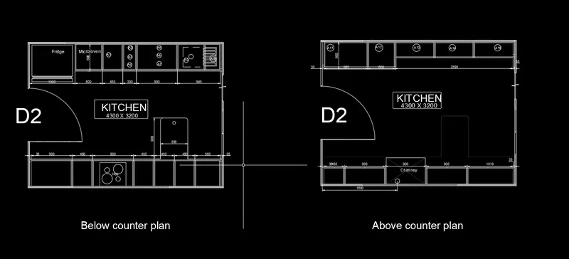
AIM: TO create the kitchen layout as shown in figure
Introduction:
kitchen layout drawing as shown in figure t draw by using AutoCAD
Procedure:
1.open AutoCAD and set units as metric
2. select the rectangle and draw the dimensions of 4300x 3200
3. select the offset and wall thickness is 150mm
4. select the object and explode
5.select the offset and given as shown in figure
6.trimmed the extra lines
7. select the multi-text to create the text
8. select the dimension given the dimension as pr drawing
9. select the hatch and select the solid and given hatch
select the hatch pattern two and given the hatch
HATCH PORTION
2.ANS
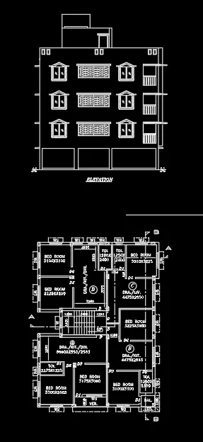
AIM: creating the elevation of using AutoCAD
procedure:
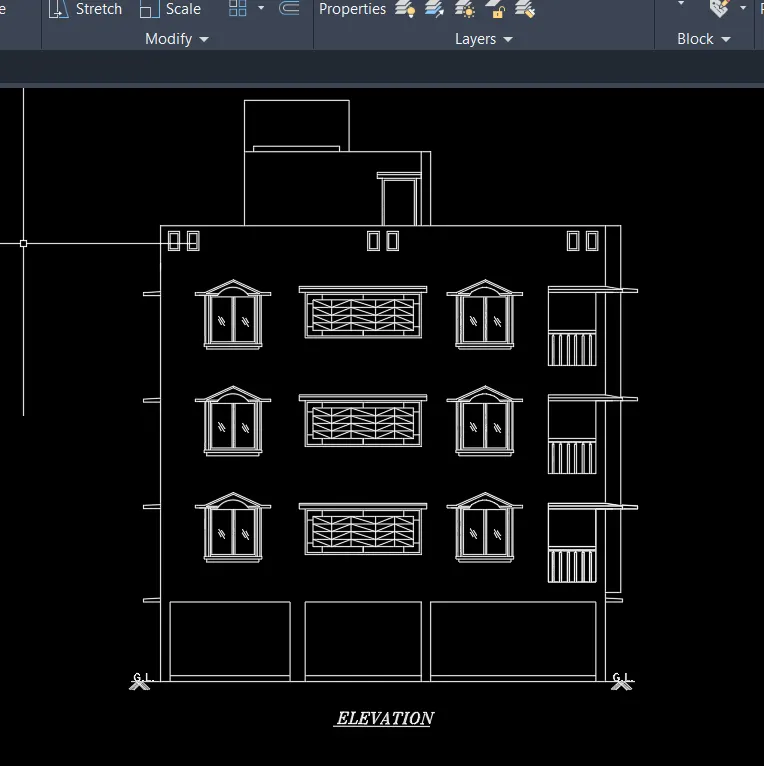
select the construction line project the plan front view
taken one horizontal construction line
select the offset 150
offset 2450
offset 2850 for each floor
offset penthouse is2500 and overhead tank is 1200
trimmed the extra lines
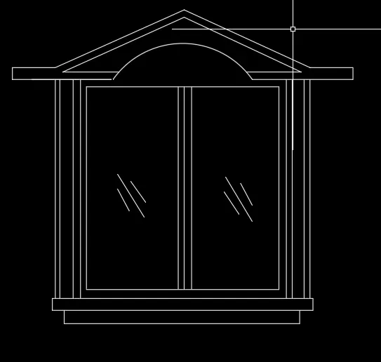
WINDOW:
select the rectangle and create the ground floor
select the rectangle and create the window take line at midpoint of rectangle
select the offset distance is 20mm and left and right side
select the polyline and create the top of the window trust
select the offset and 20mm each side
3.ANS
AIM: creating the sectional view of industrial building as shown in figure
introduction:
using the commands are
line, trim, construction line, multi- text, multi-leader, hatch, dimension
procedure:
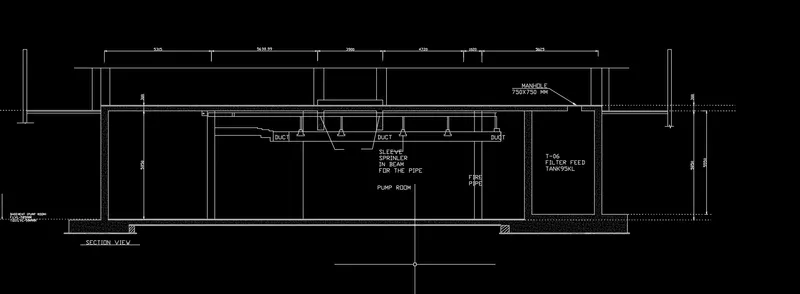
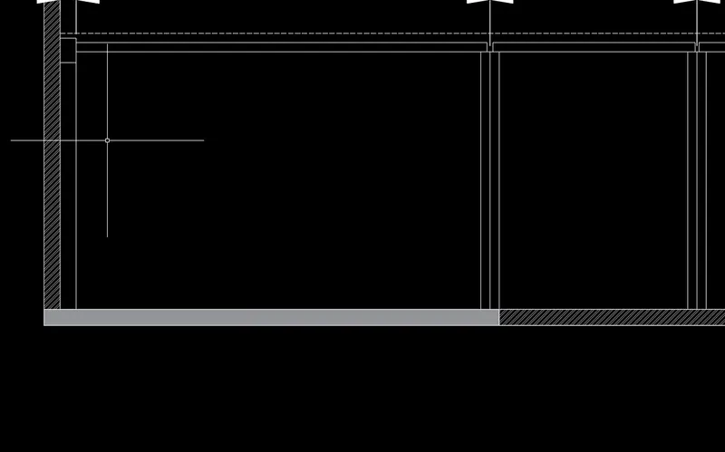
select the construction line and draw the one horizontal and vertical
select the offset and given the as per the shown figure
select the trim and trimmed the extra lines
select the dimensions and given the proper dimensions
select the multi text and text height is 100 create the texts
select the hatch and solid pattern given and select the aircon pattern to fill the concrete hatch in bed and slab