Creating Kitchen layout, Hatching of Architectural elements and sectional view of an Industrial Building in AutoCad
1. Create the layouts of the Kitchen and provide hatches pattern as shown. Also, use blocks wherever required. Provide appropriate dimensions in the plan. Assume the size of doors, appliances and others as per the standards.
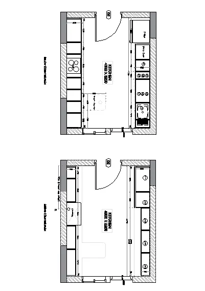
Aim:
To create the layouts of the Kitchen and provide hatches pattern as shown in the figure by using the AutoCAD software
Introduction:
Create the layouts of the Kitchen and provide hatches pattern as shown. Also, use blocks wherever required. Provide appropriate dimensions in the plan. Assume the size of doors, appliances and others as per the standards.
Procedure:
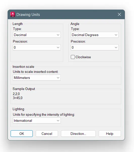
Step-1: To set the Units
- Open the AutoCAD software
- The unit of this drawing is given as shown in below
- The length type is Decimal and precision is 0
- Insertion scale is Millimeter
- Finally click OK
Step-2: To draw the Kitchen plan
- First of all uisng the Line command for draw the outer wall
- The Chamfer command to join the corner lines with eachother
- And create the door using the line and arc commands
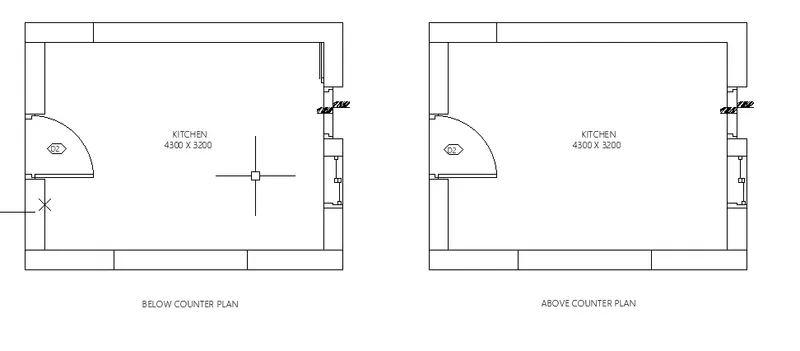
- And here, using the Line and Trim command for draw the kitchen fixtures as in the question
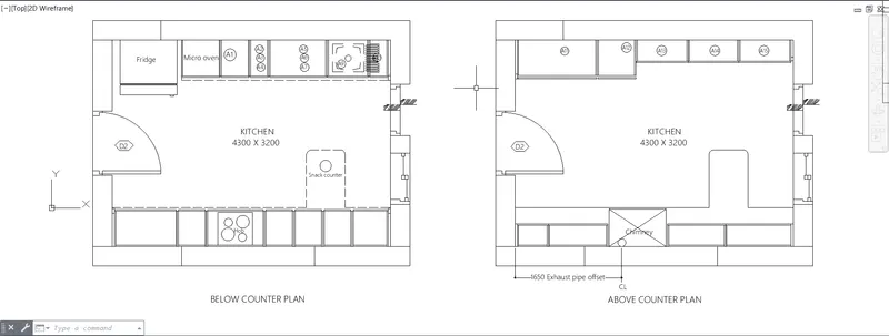
- And give the scale is given as shown in figure
- First click Bylayer for edit the line type
- And Click load and then, click that line type finally click OK
- For the snack counter line in below counter plan
Step-3: To set up the Dimension style
- The Dimension style was edit as given below drawing
- First type in command box as Dimstyle
- Give the values are as shown in below figure
- Click Modify button
- Finally click OK, Setcurrent and then, finally click close
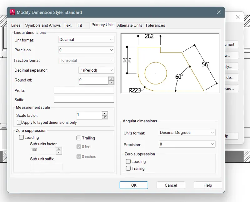
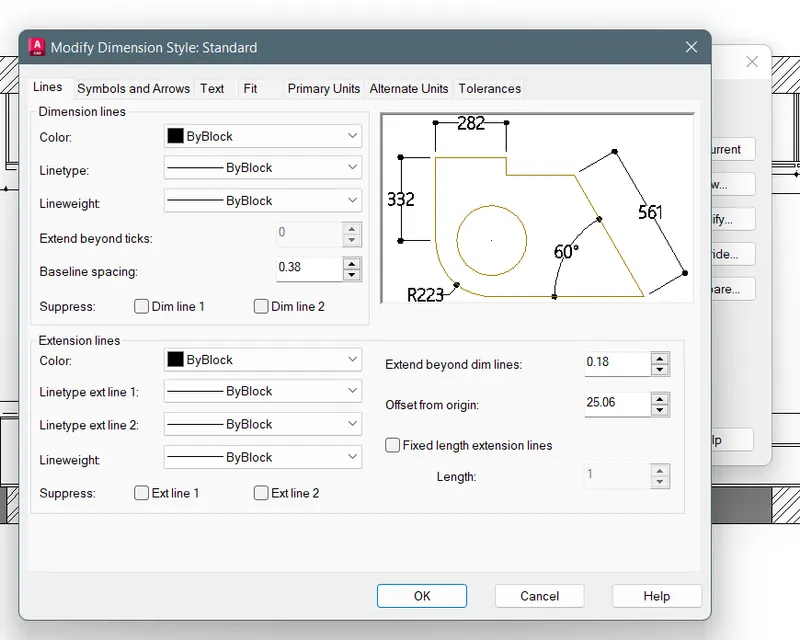
- Here, the Line, Symbols and Arrows, Text and Primary units are fix as in the all details
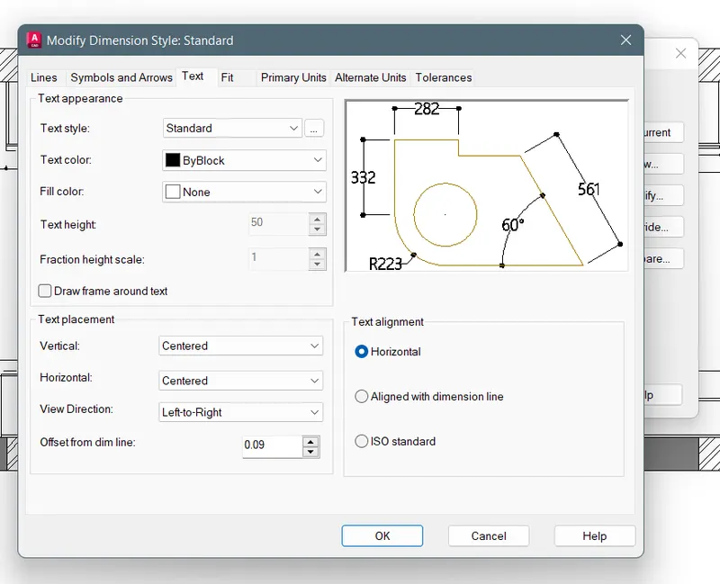
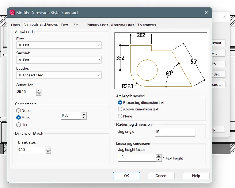
Step-4: To give dimension
- The dimensions are given by uisng the Dim command
- Then, click the points where i want to give the dimensions as given in the question
- Texting by using MText command in where i want to give the text
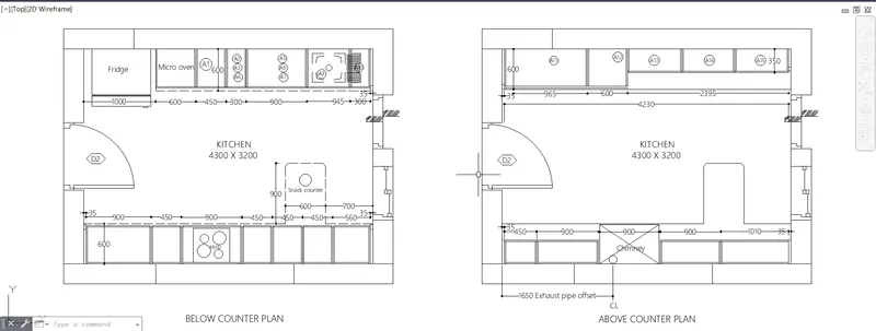
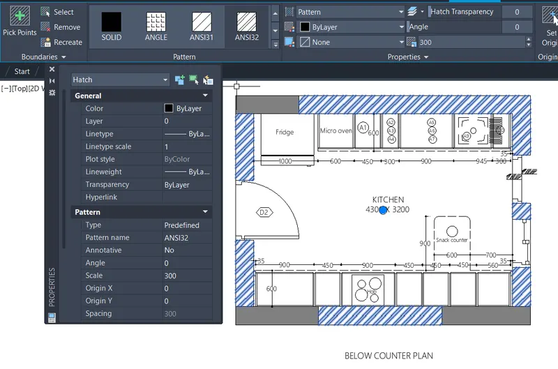
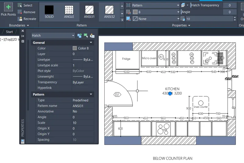
- The Hatches are using the Hatch command with the solid and wall hatch is used for giving the identify the walls
- Here, the hatches are given in as shown in figure
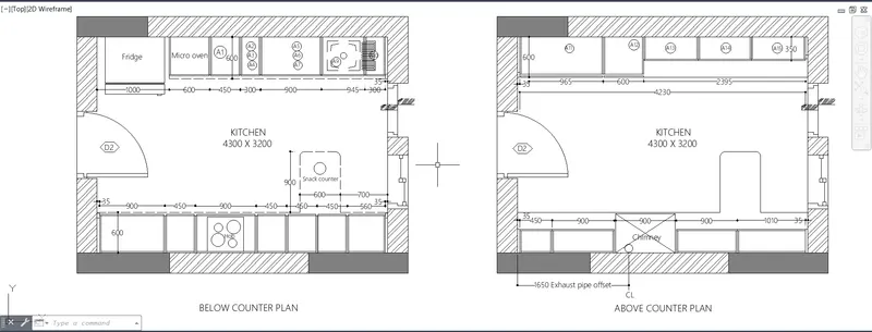
- Then, finish the drawing
Step-5: Finish the model
- The drawing is finishing by uisng the dimensions are given in the question
- The drawing is finally drawn as given in the question
- And then, finally screenshot this drawing using the Snipping Tool
- The shortcut of snipping tool is Windows key+Shift+S
Result:
The creation of Kitchen layout was drawn using the AutoCAD 2023 software with refer the dimensions as given in the question drawing
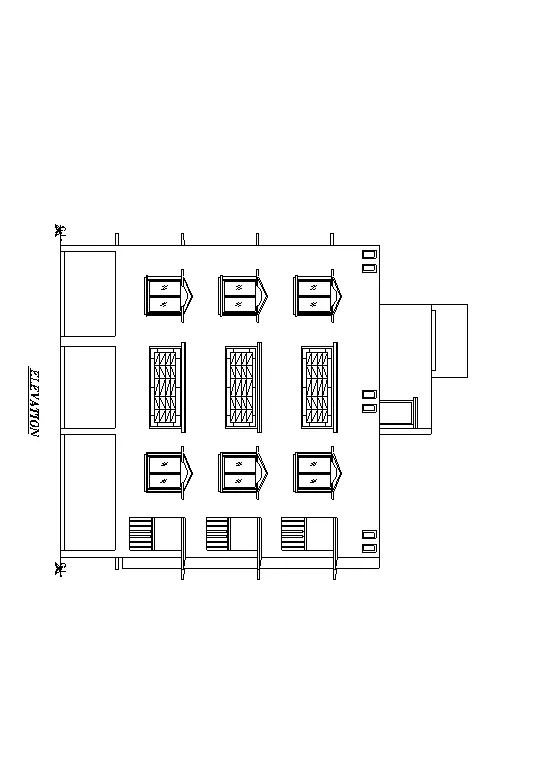
2. Create the elevation of the plan created in the Challenges 7 and apply proper hatch in the walls, doors, windows, and other architectural elements. Refer to the dimensions in Plans and sections in Challenges 7.
Refer to the elevation that needed to be created.
Aim:
To create the elevation drawing with refer the challenge 07 drawing by using the AutoCAD software
Introduction:
Create the elevation of the plan created in the Challenges 7 and apply proper hatch in the walls, doors, windows, and other architectural elements. Refer to the dimensions in Plans and sections in Challenges 7.
Procedure:
- This drawing is drawn same drawing sheet of challenge 07 and the units of the sheet also same
- Here, refer the plan and section-AA drawing for draw the elevation drawing
- And, the Line, Rectangle and Trim commands are used in this drawing
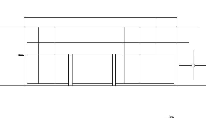
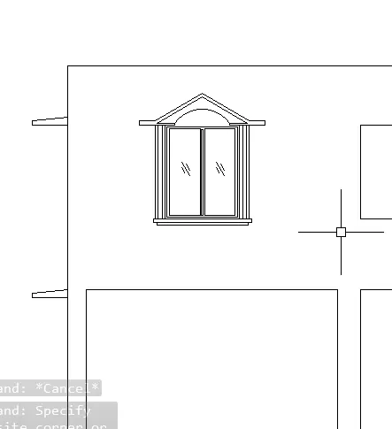
- The window drawing is drawn using the line and arc command for creating the extrusion
- And using the teim command for correct the drawing
- Then, Copy this window for another place in the same floor
- Copy the window and draw the center Jally work using the DDPTYPE for mark the points to divide the grill
- Then, divide the sections and then draw the inclined lines as given in the question drawing
- And then copy the first floor for another two floors as in the drawing
- Finally draw the opening by using the Rectangle command and copying the rectangle
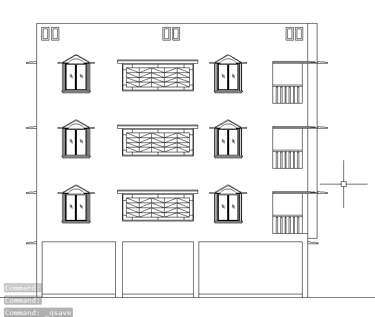
- Finally draw the Head room and the Overhead water tank by reference of section drawing
- Here, using the MText command for give a name for the drawing
- And finish this drawing
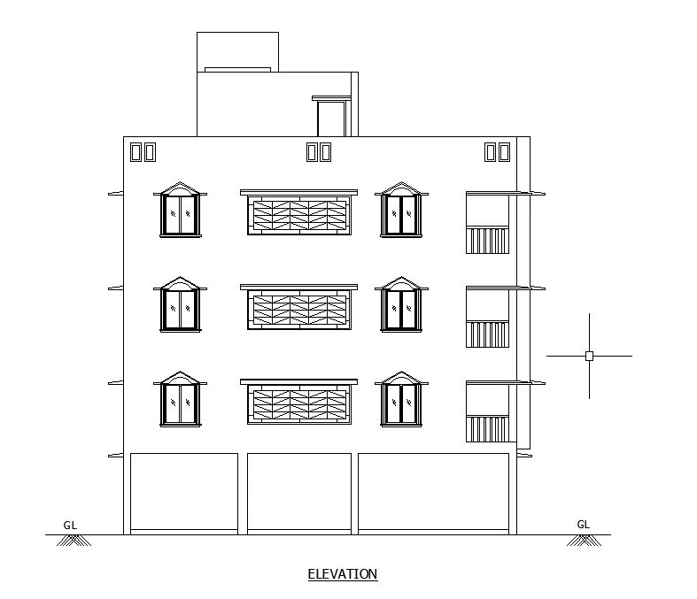
- The drawing is finally drawn as given in the question
- And then, finally screenshot this drawing using the Snipping Tool
- The shortcut of snipping tool is Windows key+Shift+S
Result:
The creation of Elevation drawing as given in the question is drawn using the AutoCAD 2023 software and refer the challenge 07 drawings for draw the elevation drawing
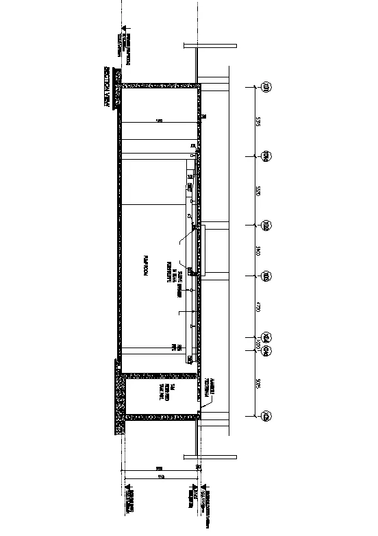
3. Create the section view of an industrial building as shown in Figure. Provide appropriate hatches and dimensions wherever required. Also, provide annotations to the drawing.
Aim:
To create the section view of an industrial building as shown in the figure
Introduction:
Create the section view of an industrial building as shown in figure. Provide appropriate hatches and dimensions wherever required. Also, provide annotation to the drawing
Procedure:
- First of all refer to the dimension of the section drawing and start to draw as the given drawing
- Here, Line command is using for draw the section drawing and assuming the not given the dimensions in the drawing
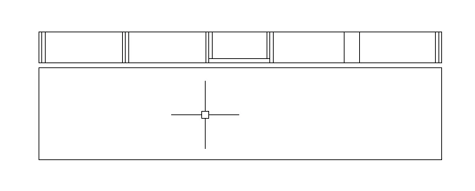
- Here, draw the duct pipe lines and the sprinklers as given in the question
- And, draw the manhole pit
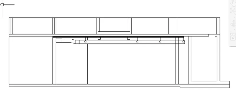
- Then, take the dimensions of this drawing using DIMLINEAR command
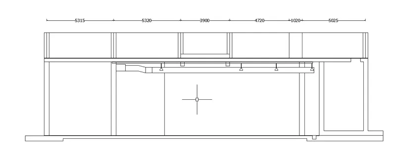
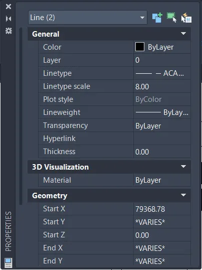
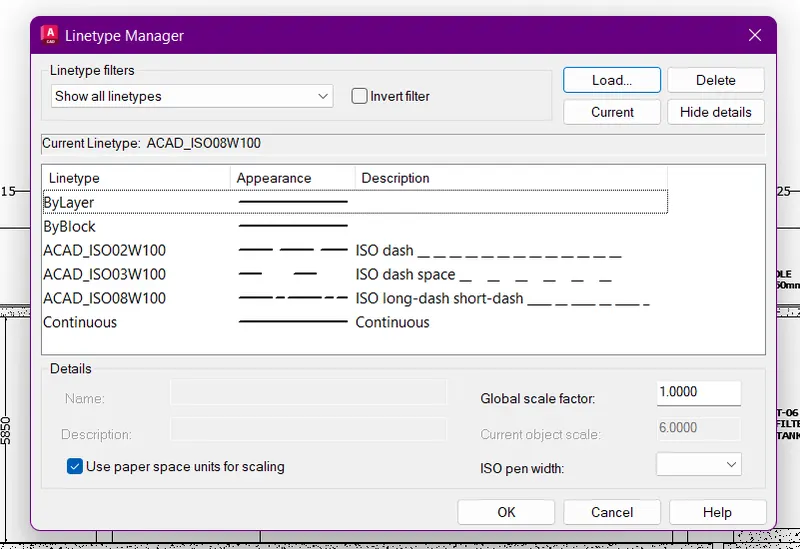
- Take the dot line for identifying the level lines in the drawing
- Using the Properties box and load this line
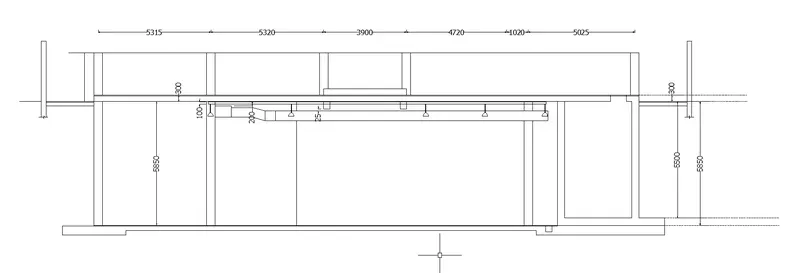
- Then, give the dimensions as in the question drawing
- Using the Hatch command for identify the surronding walls, roof and beam sections
- The hatch scale is 50 is given for the
- And he hatch name is AR-CONC

- Here, click the points the hatches is where i want to show
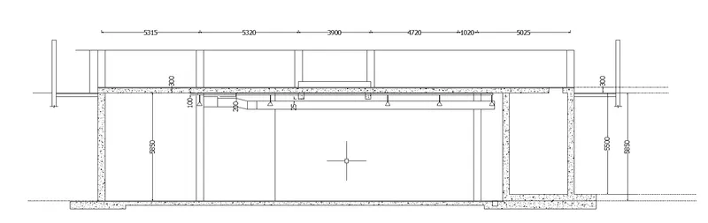
- Then, Bottom line is drawn using the line command and give the hatch of Solid to identify that position
- And using the MText command for give the parts of this drawing
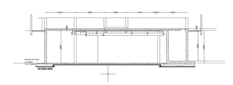
- Finally give a name for grid position of this drawing by using the MText and Circle command
- Scale the texts as i want to place in the drawing
- And finish this drawing as given in the question drawing
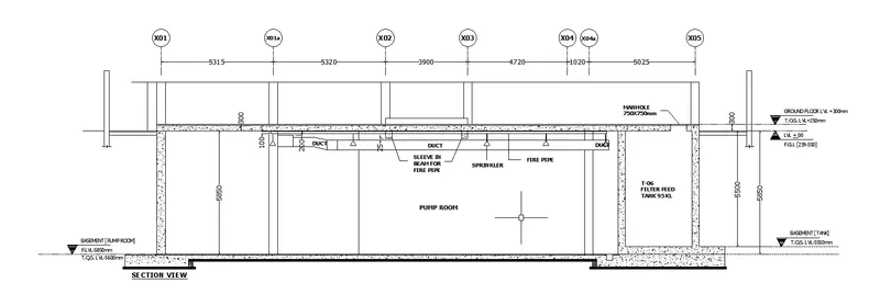
- The drawing is finally drawn as given in the question
- And then, finally screenshot this drawing using the Snipping Tool
- The shortcut of snipping tool is Windows key+Shift+S
Result:
The section view of the industrial building is drawn with reference of the question drawing and draw the sketch using the AutoCAD software