Creating Kitchen layout, Hatching of Architectural elements and sectional view of an Industrial Building in AutoCad
1. Create the layouts of the Kitchen and provide hatches pattern as shown. Also, use blocks wherever required. Provide appropriate dimensions in the plan. Assume the size of doors, appliances and others as per the standards.
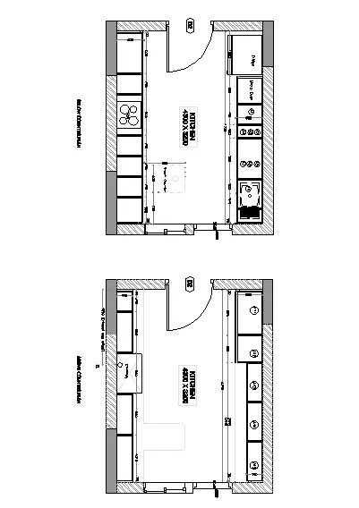
AIM:
To create the layout of the kitchen and provide hatches to it using the AutoCAD in detail.
INTRODUCTION:
The kitchen layout is the shape that is made by the arrangement of the countertop, major appliances and storage areas. The layout and floor plan create the kitchen's primary work triangle, which is the path that you make when moving from the refrigerator to the sink, to the range when preparing a meal.
COMMANDS USED:
- Limits command
- Line command
- Offset command
- Hatch command
- Dimlinear command
- Dimstyle command
- Units command
- Extend command
- Fillet command
- Trim command
- Join command
- Line weight command
- Line type command
- Object snap command
PROCEDURE:
STEP: -1
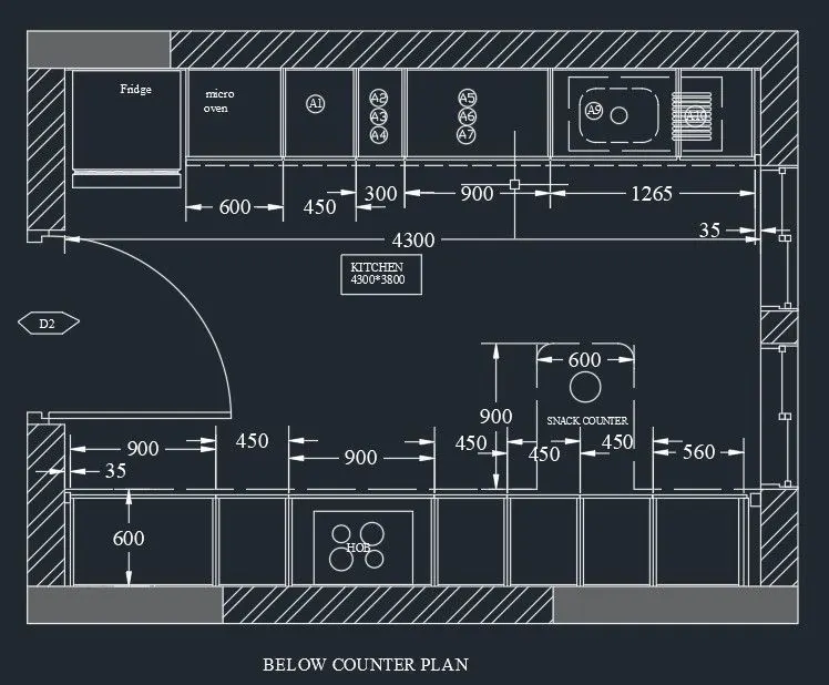
- Below is a counter plan.
- First, we have to draw the line horizontally with the length of 4300mm.
- Next draw another line from the previous line with the length of 3200mm
- Next again we draw the line from the previous line with the length of 4300 mm horizontally backwards at the top. Next, we have to join the first line and the last line which we have drawn previously.
- Next offset the four sides with the offset of 20mm outside. Next, we have to offset the line inside with the offset command with the length of 600mm, including the fridge.
- Afterwards we draw the fridge separately with other dimensions in the kitchen layout.
- Next, we need to draw a line on the opposite side to create the parts of the kitchen.
- Next divide the seven parts downsides with different dimensions compared to the upper side portion. Next leave the left and right corners with the length of 35mm at the top and bottom.
- Next put the dimensions for every part in the diagram.
- Next indicate the door as D2.
- Next, we have used the single text command and indicate the parts wherever it requires with single text command.
- And put the dimensions for every part in the diagram.
- Next draw the snack counter with the length of 600mm and width of 900mm. And draw the create the hub in the middle at the bottom of the kitchen.
- And create the windows using the line command and trim command, which is shown in the below figure.
STEP: -2
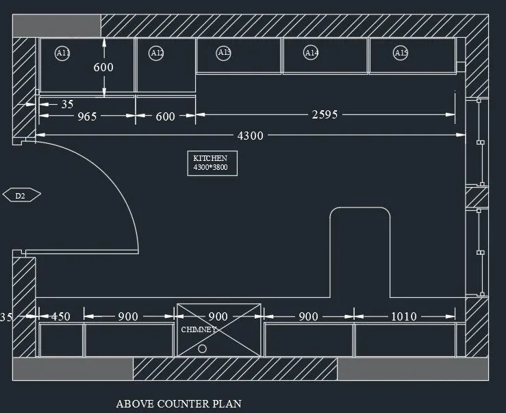
- Above counter plan:
- First, we have to draw the line horizontally with the length of 4300mm.
- Next draw another line from the previous line with the length of 3200mm vertically upwards
- Next again we draw the line from previous line with the length of 4300 mm horizontally backwards at the Next we have to join the first line and the last line which we have drawn previously
- Next offset the four sides with the offset of 20mm outside.
- Next, we have to offset the line inside with the offset command with the length of 350mm, and again we do offset of 600mm in the same side.
- And leave the space for both side corners with the length of 35mm. And do offset for the inside parts with the length of 10mm for all sides of the all parts in
- Next, we have to do the offset of 350mm at the bottom portion of the kitchen. And the bottom portion into five parts, and again offset them with the length of 10mm.
- Next, we have to use the different hatch styles to hatch the walls in the kitchen layout.
- Next, we have to draw the doors using the line command, circle command and trim command
- Next, we have to draw the windows using the line command and trim command.
- And next we have to use the dimlinear command to put the dimensions wherever they are required.
- Next use the single text command to indicate the kitchen parts in the kitchen layout which we have drawn in the below figure. Finally, we draw the snack counter with the length of 600mm and width of 900mm.
RESULT:
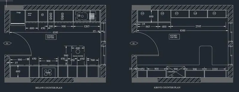
- The kitchen layout is drawn successfully in the AutoCAD with proper hatches provided in detail.
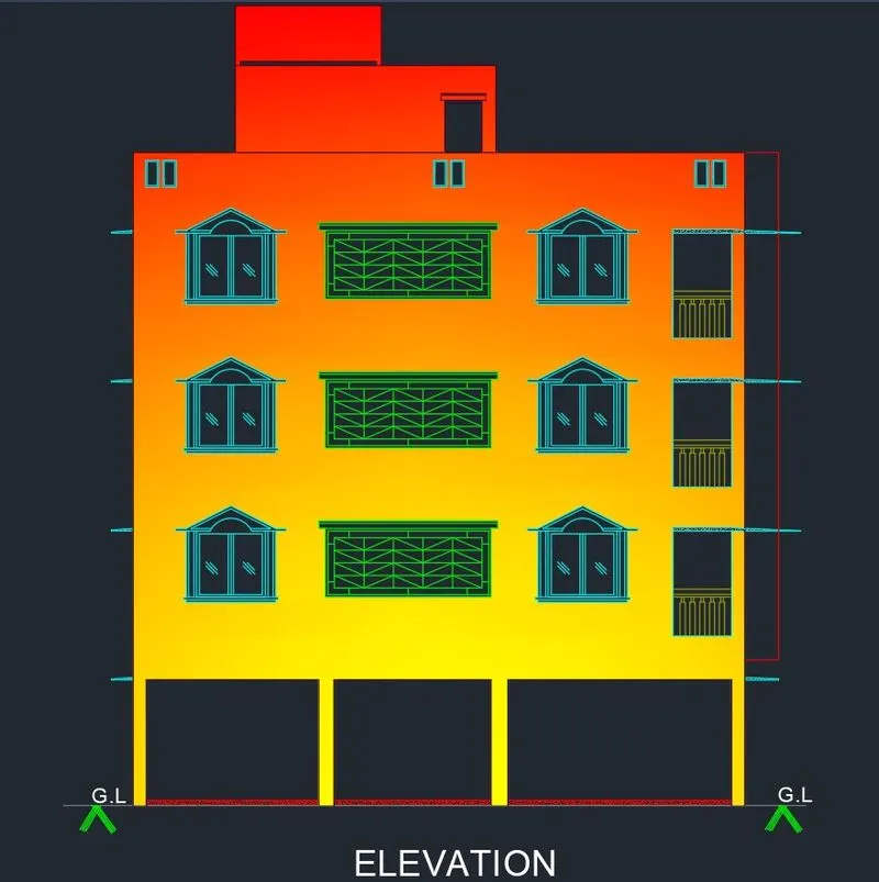
2. Create the elevation of the plan created in Challenges 7 and apply proper hatch in the walls, doors, windows, and other architectural elements. Refer to the dimensions in Plans and sections in Challenges 7.
Refer to the elevation that needed to be created.
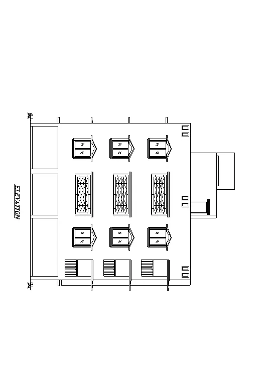
AIM:
To Create the elevation of the plan created in Challenges 7. And need to apply proper hatches in the walls, doors, windows, and other architectural elements
INTRODUCTION:
COMMANDS USED:
- Limits command
- Line command
- Offset command
- Hatch command
- Dimlinear command
- Dimstyle command
- Units command
- Extend command Fillet command
- Trim command
- Join command
- Line weight command
- Line type command
- Object snap command
- Rectangle command
- Zoom command
PROCEDURE:
STEP 1) SELECTION OF MODAL FOR DRAWING
- Open AutoCAD
- STARTUP enters for new drawing
- Enter new value for startup 1 enter
- Create new file (a dialog box open START FROM SCRATCH)
- Select default setting as METRIC click on OK
- UN enter for unit setting
- Select DECIMAL, precision 0 in type
- Insertion scale select MILIMETER Click OK
- LIM enter for set limit
- Specify lower left corner 0,0 enter
- Specify upper right corner 20000,20000 enter
- Z enters for zoom
- Zoom for select ALL or A enter
STEP 2) ATTACHING DRAWING
- Enter XREF for external reference command
- Click on icon to attach drawing
- Select reference file from dialog box
- Browse and open 7th week of challenge
- Attach external reference dialog box open then click on ok
- Now again, enter command XREF for attached drawing to bind>insert
STEP3) CRETAE DRAWING
- Select exist layer as wall
- With the help of XL line command create projection of the floor plan
- Create horizontal line for level of floor
- Trim and erase to remove unwanted line
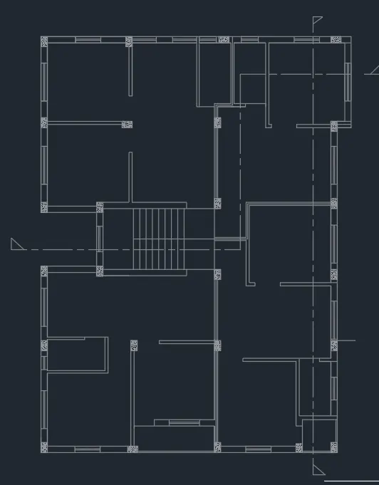
STEP4) CREATE WINDOW
- With the help of line command to create window
- First of all, create window frame by the offset command at 50 distances
- Then create window panel
- The create pillars for chajja with the help of offset
- Create an incline line then mirror it
- Create arc for chajja
- After that trim and erase to remove all unwanted lines
- Finally get the shape of window

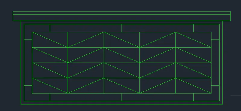
STEP 5) CREATE VARANDA GRILL
- Create grill in the projection lines of between columns
- Line command to help the creation of the design like given in drawing
- Offset and trim command used to create the grill
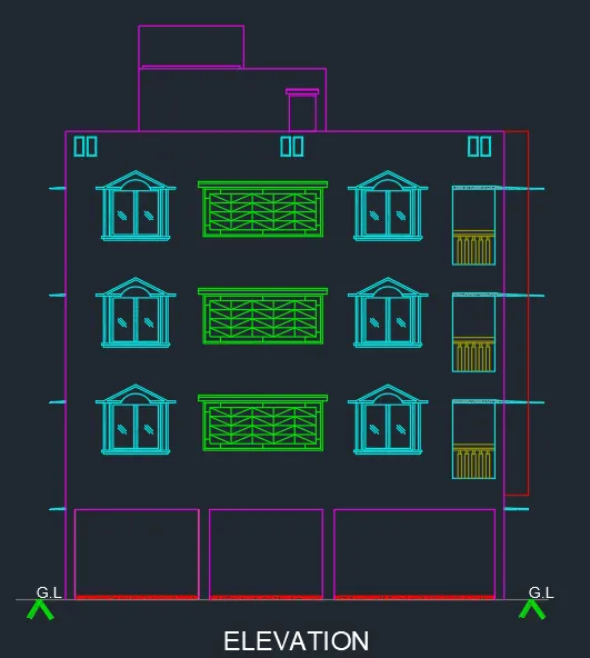
STEP 6) CREATE ELEVATION
- Choose layer according to elements
- Copy window and grill to paste each level
- Create chajja and other designs which are given in drawing
- Create balcony railing and chajja
- Create mummty slab level
- Create an overhead tank
STEP 7) HATCHING
- H enters for hatch
- Select gradient linear
- Change colure
- Pick internal point
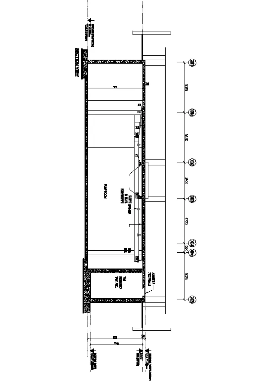
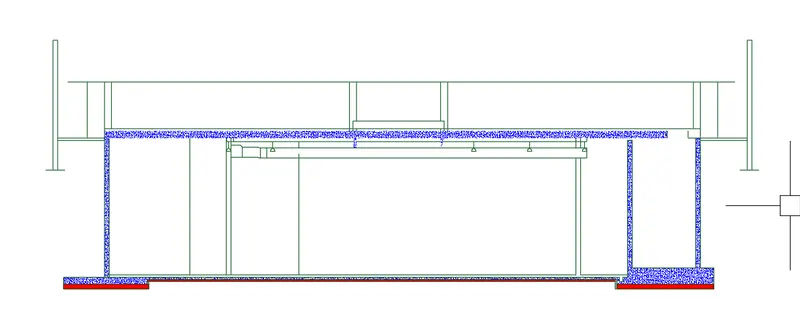
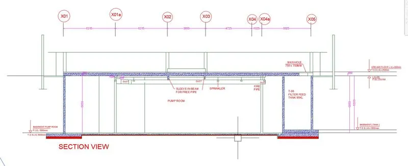
3. Create the section view of an industrial building as shown in Figure. Provide appropriate hatches and dimensions wherever required. Also, provide annotations to the drawing.
AIM:
To draw the section view of an industrial building as shown in figure.
INTRODUCTION:
The section is created in AutoCAD by using tools like Draw, Modify, Annotation, Layer and Properties. Text, dimension and hatch are provided. The procedure of kitchen layout is explained in detail with figures and the final result is given.
PROCEDURE:
STEP 1) SELECTION OF MODAL FOR DRAWING
- Open AutoCAD
- STARTUP enters for new drawing
- Enter new value for startup 1 enter
- Create new file (a dialog box open START FROM SCRATCH)
- Select default setting as METRIC click on OK
- UN enter for unit setting
- Select DECIMAL, precision 0 in type
- Insertion scale select MILIMETER Click OK
- LIM enter for set limit
- Specify lower left corner 0,0 enter
- Specify upper right corner 20000,20000 enter
- Z enters for zoom
- Zoom for select ALL or A enter
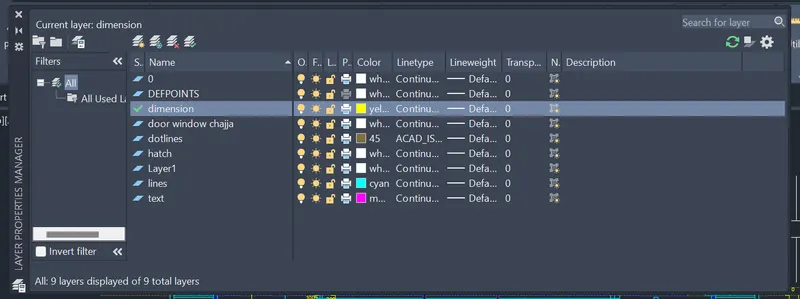
STEP 2) ASSIGNED LAYER PROPERTY
- Create some new layer for the section
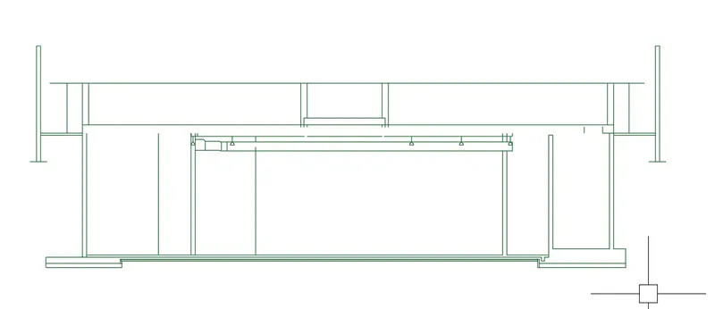
STEP 3) CREATE LINES FOR SECTION
- XL line command to create horizontal and vertical line
- Trim over intersection point
- Take offset as given distance
- Create as per given drawing
STEP 4) HATCH
- H enters for hatch
- Fill the wall with pattern of AR-CONC and set scale
- Bottom fill with solid pattern
STEP5) TEXT AND DIMENSION
- Create multileader for showing the direction of element
- And type the of element
- Multiline text used for other text
- Change font and style of text
- Set layer after provide text
- DIMLIN enter of showing distance
-
RESULT:
After following the above step by step procedure got result as shown below