Creating Kitchen layout, Hatching of Architectural elements and sectional view of an Industrial Building in AutoCad
-
- AIM:- To draw (a) Kitchen Layout (b) Elevation (c) Section
- Commands used :
1. Dimension - Command "DIM".
- To edit dimension style, text, etc. command "D"
- To move the dimension line select the grip point and move
- If we place the mouse on grip points of extension lines, we can see options such as stretch, continue dimension baseline dimension, and flip arrow.
- If we need to move or change the text's position, right-click the text's grip point: stretch, move with the dim line, move text only, proceed with the leader, above the dim line, center vertically, reset text position.
- Command "DIMEDIT" is used to edit the dimension line, to make it oblique, rotate, and change it to default.
- For text justification, the justification tab is selected from the toolbar in annotate tab.
- Command "DIMBREAK" to break the overlapping dimensions.
- Command "DIMCONTINUE" to continue dimensioning.
2. Dimension Style - Command "DIMSTYLE".
- We can create our dimension style from the "new" menu.
- In this, all the lines included in dimension (extension line, dimension line), their properties (color, lineweight, etc.) can be changed, and we can suppress extension lines.
- In Symbols and Arrows, we can change the shape of the arrowhead, arrowhead size, center marks, breaksize, etc.
- In the text, we can set the height of the text, color, and style.
- In fit option, if there is no space to place text and arrows in extension lines, options can be selected whether either text or arrows or both text or arrows, etc., text placement, overall scale adjustments (all the features of dimension lines i.e. arrows, text, etc. will change to be input scale accordingly).
- Primary units, we can select the unit format (decimal, engineering, architectural), precision, decimal, separator, etc.
- In alternate units, we can set another unit other than the primary unit, then two units will be displayed in the units position is all managed here.
- In tolerance, we can set the tolerance level and how it should be displayed in the drawing.
3. Offset - Command "O"
4. Trim - Command "TR"
5. Line - Command "L"
6. Text - Command "TEXT"
7. Layer - Command "LAYER"
8. Match properties - Command "MATCHPROP"
9. Multileader - Command "MLEADER"
10. Rectangle - Command "REC"
- KITCHEN LAYOUT:
- Aim: To draw a Kitchen layout
- Procedure:
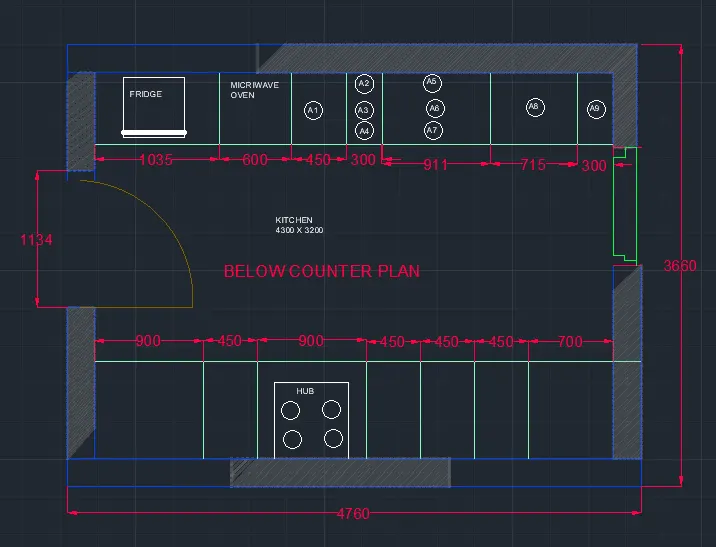
- Below counter plan
- Drawing the WALL
- Draw a rectangle of 4300 x 3200mm
- Draw an offset of 230mm as wall thickness towards the outside.
- Drawing Cabinets:
- The fridge is drawn on the leftmost side by a rectangle tool.
- Take an offset of 1000mm and start drawing the slab showing the cabinet below.
- Offset 600mm for the cabinet below for the microwave oven, give an offset of 20mm to show the partition of the cabinet below.
- For the width of the cabinet give 600mm offset, give 20mm inside offset, and 10mm offset for thickness.
- From 600mm offset of microwave cabinet, give an offset of 450mm for A1.
- From that gives 300mm offset A2, A3, and A4.
- From 300mm offset give another offset of 900mm for A5, A6, and A7.
- Draw a 35mm offset from the right side for the hinge and give a thickness of 20mm.
- From the 35mm draw an offset of 300mm towards the left for the cabinet below the sink drain and the rest will be the cabinet below the sink (assumed 300mm from the right).
- Erase the extended line and trim the horizontal line for the opening of doors.
- Drawing right cabinets and hob:
- Give 35mm offset from the left and create a hinge.
- For the width of the cabinet give 600mm offset, give 20mm inside offset, and 10mm offset for thickness.
- For 35mm give 900mm offset.
- Give an offset of 450mm from the 900mm offset.
- Again offset at a distance of 900mm.
- Offset a distance of 450mm three times from the respective preceding offset.
- From the right side offset 35mm for the hinge and the rest distance will be 630mm which shows the top of the cabinet.
- Offset a distance of 20mm on both sides of all offset lines (from all divisions).
- To create doors, extend the line of all the divisions and give a 10mm offset on both sides in the 10mm offset given for thickness.
- Erase the extended line and trim the horizontal line for the opening of doors.
- Extend the center line to the thickness of 3 cabinets from the left.
- Hob is drawn with a rectangle and circle tool in the plan of the third cabinet from the left.
- Layer the objects and do the dimensions and annotation.
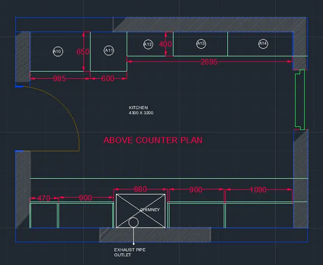
- Above Counter plan: Copy the wall of the below counter plan as the dimension are the same.
- Drawing right side counter:
- draw a width of 350mm from the wall to the inside and offset 20mm to show the thickness.
- Offset a distance of 35mm from the left side of the wall.
- Next, offset 450mm for the top of the cabinet.
- offset 900mm 3 times for the next cabinets.
- From the right side offset 35mm, the rest distance of 1095 will be cabinet.
- For the second 900mm offset, draw a rectangle and from a distance of 1650mm from the left side of the wall, draw a circle for the chimney.
- For the rest of the offset, offset 20mm on both sides for the thickness.
- Drawing left side counter:
- From the left side, the wall takes a 35mm offset to draw the hinge.
- Draw 600mm offset as width from the horizontal wall.
- Draw 10mm offset to dhow the door.
- Draw an offset of 38mm from the 10mm door for the cabinet.
- From 35mm hinge offset 965mm to the right A11.
- From that offset 600mm for the next cabinet A12.
- Take an offset of 350mm from the horizontal wall as the width of the next cabinets.
- Offset a di 35mm from the right.
- The rest distance is 2665mm which is divided into 3 equal parts A13, A14, and A15.
- Then offset 20mm on both sides of divisions and also 20mm in front for doors.
- offset 10mm on the backside for showing thickness.
- Layer the objects and do the dimensions and annotation.
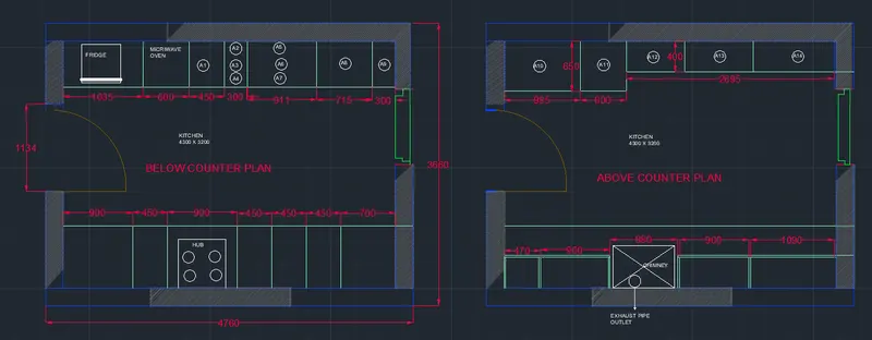
- RESULT:
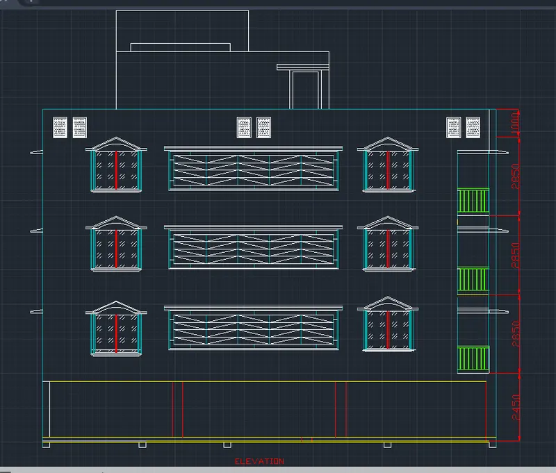
- ELEVATION OF PLAN IN CHALLENGE 7
- Aim: To draw the elevation plan of challenge 7 and do the hatching.
- Procedure:
- Copy the plan from the previous drawing of challenge 7 to pick the measurements.
- Select the outer wall lines of the plan and copy these lines separately.
- Refer to the drawing in the challenge for the elevation drawing.
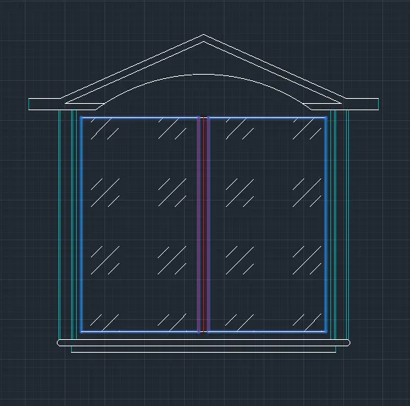
- Draw a rectangle of 1500 x 1500 mm for the side windows.
- Offset at 50mm towards inside.
- Explode both the rectangles.
- Divide the inner rectangle into the half with a line to create window panels.
- Offset at 35mm towards the outer side to draw the Jamb.
- To draw the shed above the window draw a triangle with a height of 200mm.
- Draw an arc with 3 points.
- Copy the window at all the respective spaces for the windows.
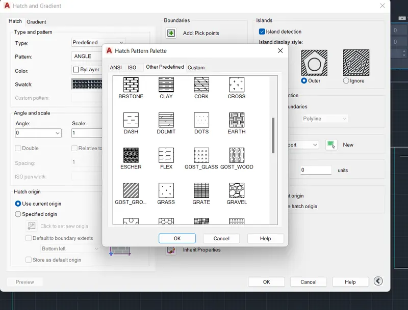
- Select the hatch option.
- Go to the options in the hatch and select the hatch pattern of Glass.
- Specify the hatch scale as 10.
- Pick the internal points to do the hatching on the window glasses.
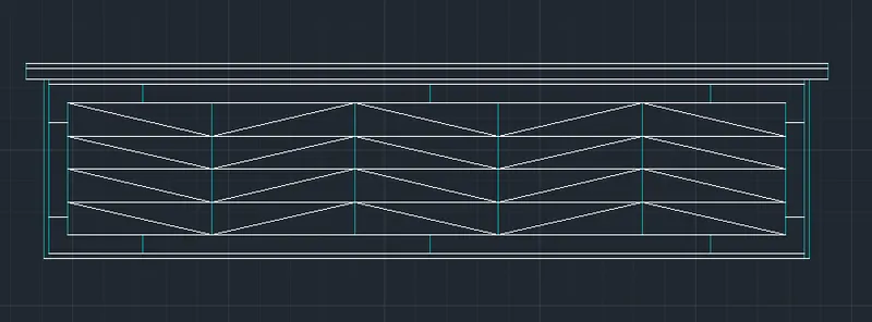
- For the windows in the middle, Draw a rectangle of 10000mm X 1500mm.
- Offset the rectangle at 30mm towards the inside.
- Again offset the rectangle at 150mm towards the inside.
- Explode all the three rectangles.
- Offset the top line of the outermost rectangle at 50mm and 30mm for the shed.
- Now divide the innermost rectangle into 5 equal parts vertically and 4 equal parts horizontally with the help of calculated and offset.
- Upon getting the mesh to draw zig-zag lines with the help of the line command.
- Copy the zig-zag line to all the boxes.
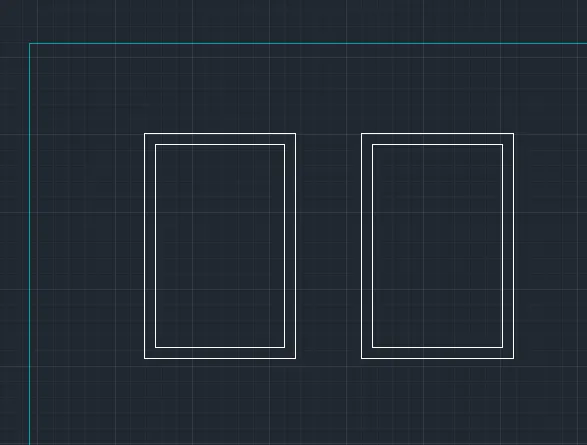
- Draw a rectangle of 400m x 730mm
- Offset the rectangle at 35mm towards the inside.
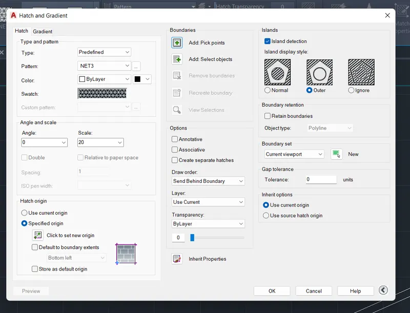
- Select the hatch option.
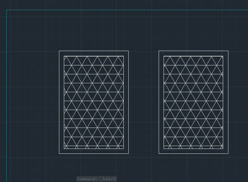
- Select the NET3 pattern and scale at 10.
- Select the points to do the hatching of the ventilators.
- Copy the ventilators at the appropriate places.
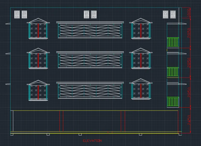
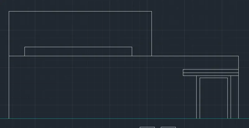
- Select the line command and draw the mummy and overhead water tank.
- Draw the door in mumty of 1500mm x 3000mm.
- RESULT:
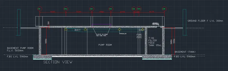
- SECTION VIEW OF INDUSTRIAL BUILDING.
- Aim: To draw a sectional view of an industrial building, hatch, and annotate.
- Procedure:
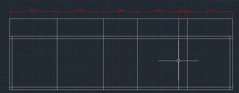
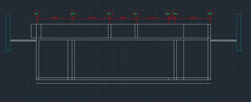
- Draw the bottom lines with the help of line command at the distances of 5315mm, 5320mm, 3900mm, 4720mm, 1020mm, and 5175mm.
- Offset the bottom line at a distance of 300mm for the flooring.
- Again offset the above line at 5550mm for the slab level.
- Again offset the slab line at 300mm for the slab thickness.
- And lastly, offset at the distance of 2000mm for the roof of the building.
- Draw vertical lines from bottom to top at each node.
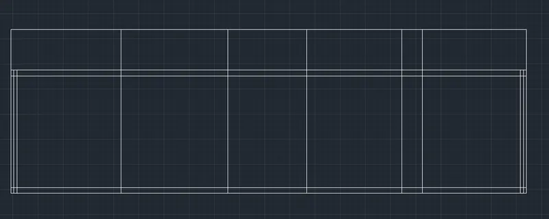
- Select the DIM command and do the dimensioning.
- Draw the circles and mark the columns in them with help of MTEXT.
- Give them a color through layer option.
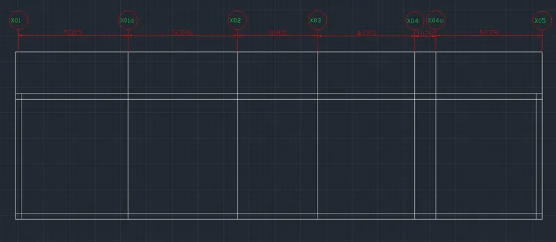
- Trim off the unnecessary lines.
- Offset the lines at X01o, X02, X03, and X04o at 150mm towards both sides.
- Draw boundary walls on both sides of the building.
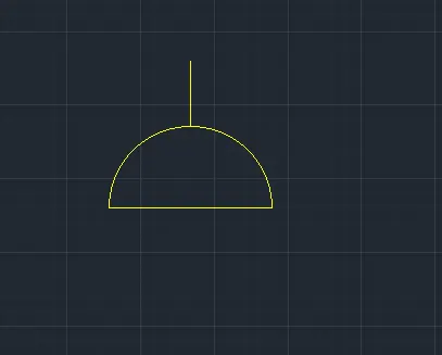
- Draw a circle.
- Draw its horizontal diameter.
- Trim off half of it.
- Draw a line on it to make a sprinkler.
- Give it a color through the layer specified as the SPRINKLER.
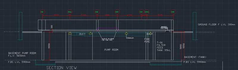
- With the help of MTEXT do the annotations accordingly in the drawing.
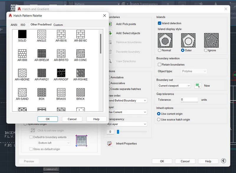
- Select the hatch option.
- Select the hatch pattern as AR-CONC with the scale specified as 1.
- Pick the internal points to depict the concrete structures.
- Again select the hatch option.
- Select the SOLID color WHITE and pick the internal points to depict the PCC.
- RESULT: