Creating Kitchen layout, Hatching of Architectural elements and sectional view of an Industrial Building in AutoCad
1.AIM
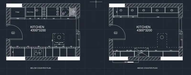
To Create the Kitchen Layout and provide hatches pattern as shown in the Figure below
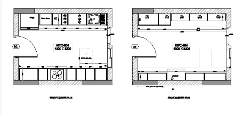
INTRODUCTION
Kitchen layout planning is very important if you want to get the most from your new kitchen .It will help ensure you are able to keep your space neat and tidy .
COMMANDS USED
- Unit command
- Limit command
- Line command
- Offset command
- Trim command
- scale command
- Rectangle command
- Dimlinear command
- Mtext command
- Dtext command
- Dimstyle command
- Move command
- Copy command
- Divide command
- Block command
- Insert command
PROCEDURE
STEP 1
- Open a new file
- In the command line type units , select the unit and also set the precision
- In the command line type 'LIMITS' and specify the limits at lower left corner and upper right corner as
- Then zoom all
STEP 2
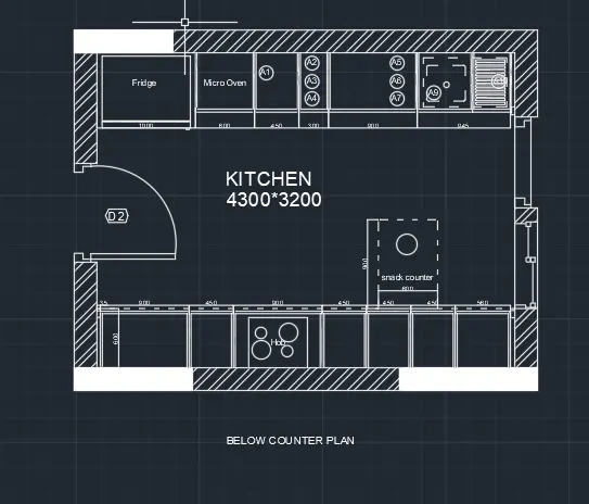
BELOW COUNTER PLAN
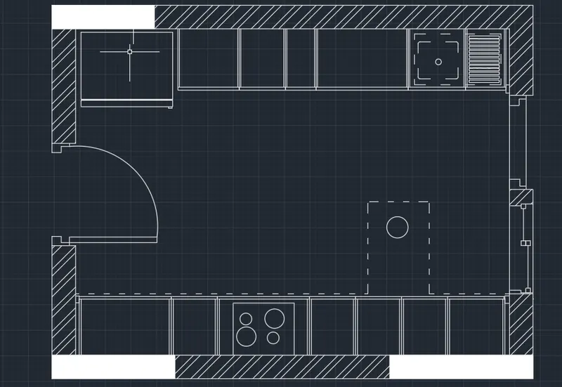
- Using rectangular command draw a rectangle of 4300*3200 and explode it
- Using offset command offset the rectangle by 230
- Then by using fillet command fillet the offsetted edges
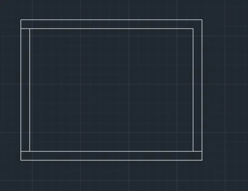
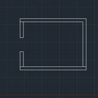
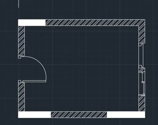
- Make door opening of 1000
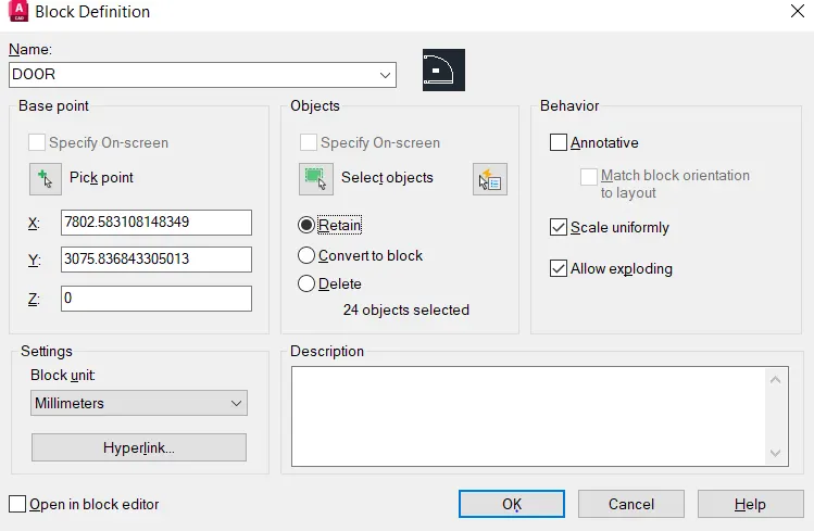
- make the door block and insert it in the drawing using insert command
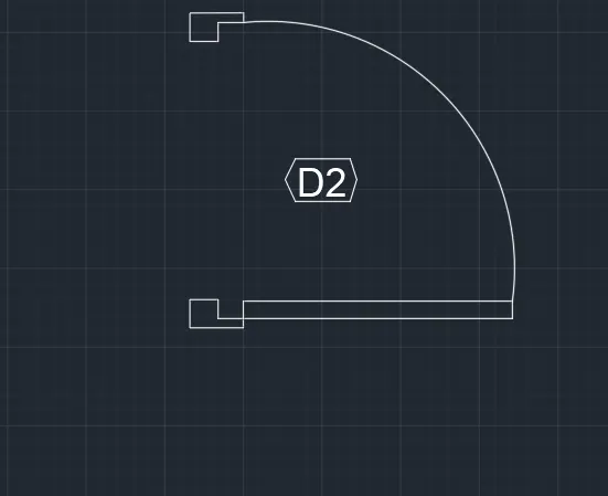
- Window opening is made
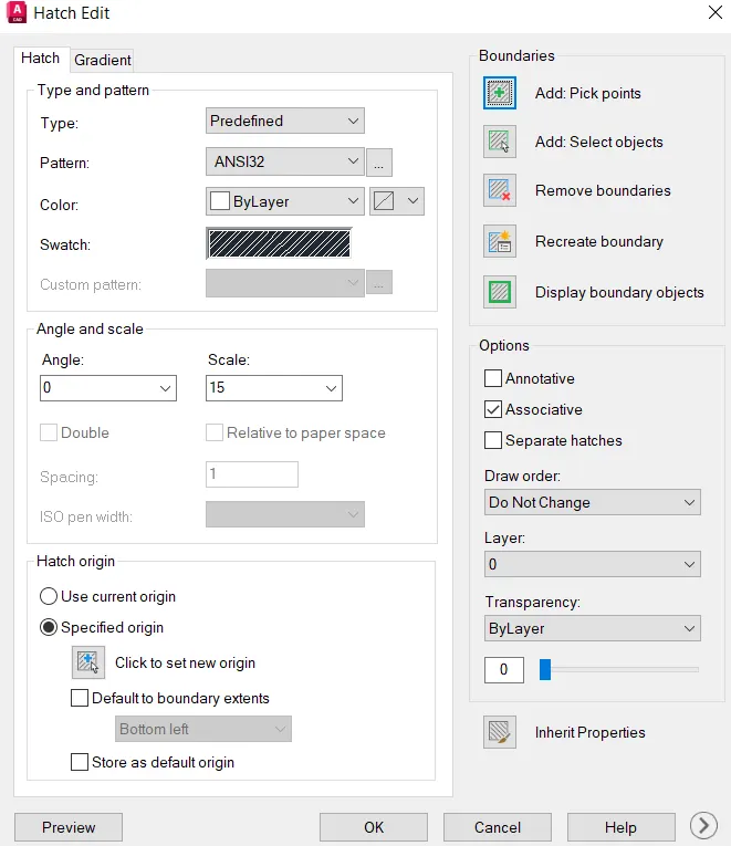
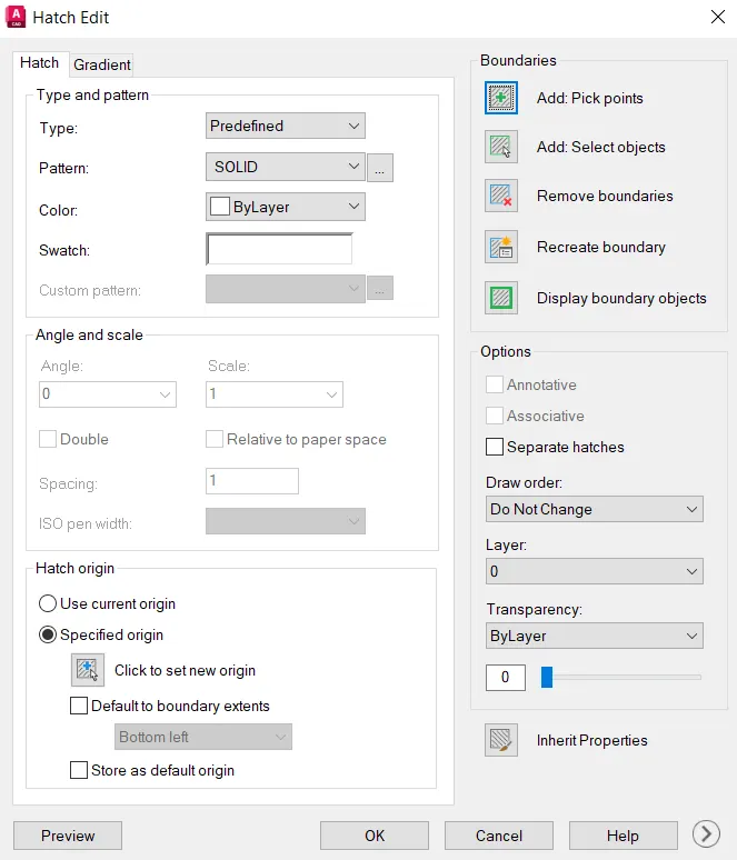
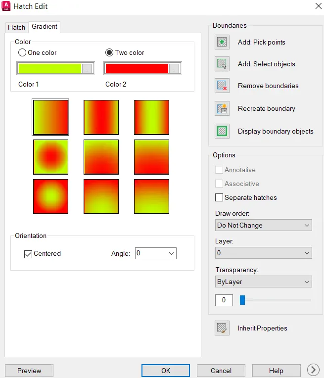
- Using the hatch command hatching is done for the wall
- Select the pattern here for wall ANSI32 is selected and solid
- Scale the pattern accordingly
- Then click the area or object to be hatched and then press enter
- Using properties panel can change the hatch type, colours , angle and can scale for the hatch
- Using offset command offset 600 from top of the room to draw kitchen platform
- Using rectangular command draw rectangle as per the dimention for drawing fridge
- by using offset command offset it by 600 from side to get micro oven ,450 for A1 part,300 for A2/A3/A4, 900 for A5/A6/A7 and 300 ,945 and 35
- in the bottom portion of the room offset from side by 35, 900,450,900,450,450,450,560,35 and from bottom offset by 600
- trim the unwanted lines
- in the command using line type load the dotted lines
- Using text command to text the given annotations
- using dimension command DIMLIN given dimension to the plan
STEP 3
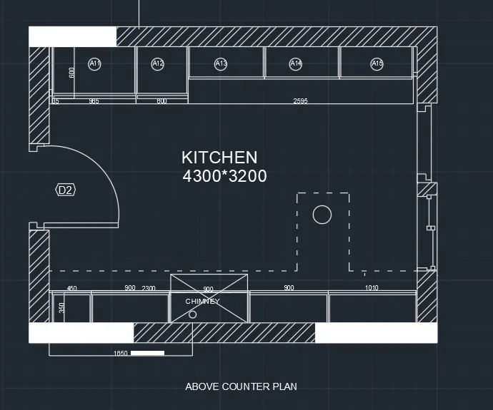
ABOVE COUNTER PLAN
- Using rectangular command draw a rectangle of 4300*3200 and explode it
- Using offset command offset the rectangle by 230
- Then by using fillet command fillet the offsetted edges
- Make door opening of 1000
- make the door block and insert it in the drawing using insert command
- Using the hatch command hatching is done for the wall
- Select the pattern here for wall ANSI32 is selected and solid
- Scale the pattern accordingly
- Then click the area or object to be hatched and then press enter
- Using properties panel can change the hatch type, colours , angle and can scale for the hatch
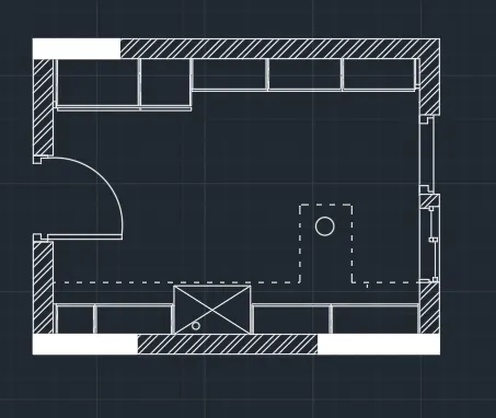
- Using offset command offset 600 from top of the room to draw kitchen platform
- Offset from left side first 35 then again offset as 965,600,2595
- Offset 350 from the bottom portion of the kitchen
- in the bottom portion of the room offset from side by 35,450,900,900,900,1010,35
- trim the unwanted lines
- Using text command to text the given annotations
- using dimension command DIMLIN given dimension to the plan
RESULT
------------------------------------------------------------------------------------------------------------------------------------
2.AIM
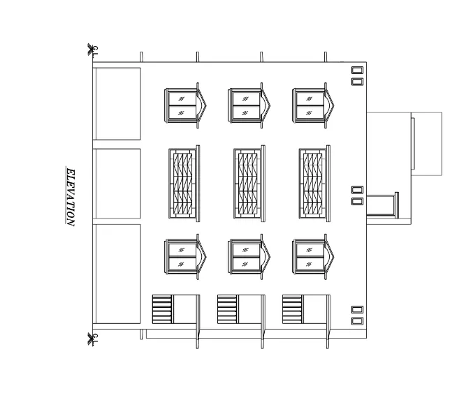
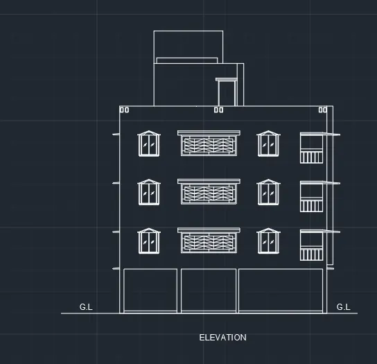
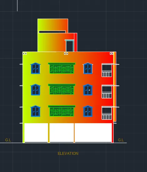
To create the elevation of the plan and apply proper hatch in the walls, doors, windows, and other architectural elements.
INTRODUCTION
- An elevation drawing is drawn on a vertical plane showing a vertical depiction
- Specific type of drawing used to illustrate a building or portion of a building
- Elevation drawings are orthographic projections
- There are different type of elevation drawings :
- Elevation
- Interior elevation
- Elevation call out
- Elevation Detail
COMMANDS USED
- Unit command
- Limit command
- Line command
- Offset command
- Trim command
- scale command
- Rectangle command
- Dimlinear command
- Mtext command
- Dtext command
- Dimstyle command
- Move command
- Copy command
- Divide command
- Block command
- Insert command
PROCEDURE
STEP 1
- Open a new file
- In the command line type units , select the unit and also set the precision
- In the command line type 'LIMITS' and specify the limits at lower left corner and upper right corner as
- Then zoom all
STEP 2
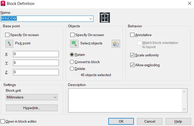
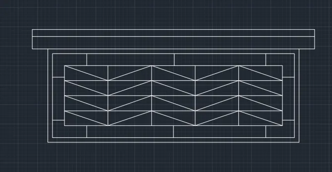
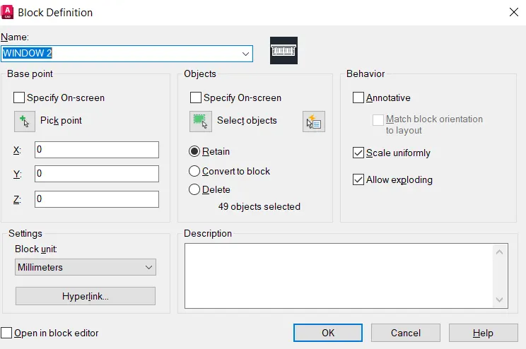
window
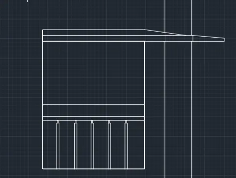
- According to the standard size window, architectural elements and balcony are drawn and created it as block using block command
- using line , rectangle, offset ,trim and arc command is created
- Balcony
STEP 3
- Project the lines from the plan using construction line
- trim the unwanmted lines
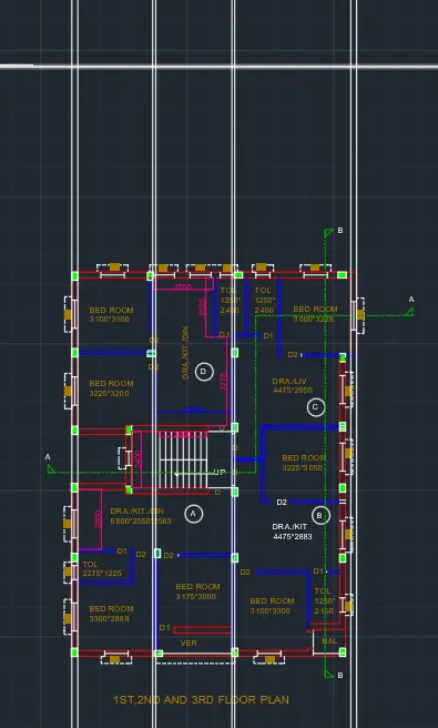
- using offset command offset 150 mm from the ground level
- Then offset 2450 for ground floor
- offset 2850 for second floor
- offset 2850 for third floor
- offset 1000 for parapet wall
- offset 2500 from terrace level to mumty
- offset 600 and 1200 for O.T.H
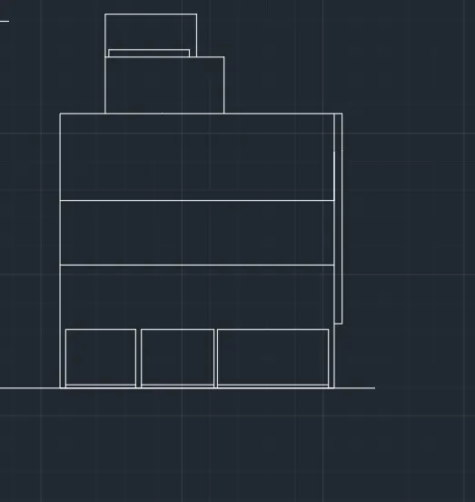
- Next we need to draw the sunshades as provided in the drawings
- then have to insert the windows , architectural elements and balcony into the drawing
- using Mtext command enter the text
STEP 4
- Using hatch command hatch the doors , windows and architectural elements
RESULT
---------------------------------------------------------------------------------------------------------------------------------------------
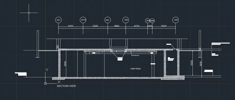
3.AIM
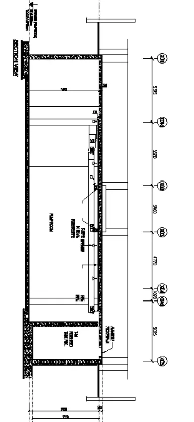
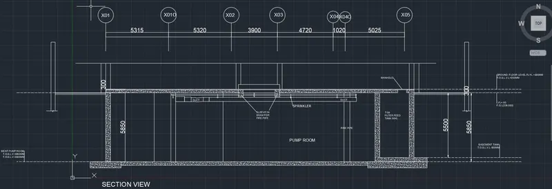
To create the section view of an industrial building as shown in Figure
INTRODUCTION
- A section drawing is also a vertical depiction , but one that cuts through space to show what lies within
- This is represented as a 'section drawing' or 'sectional drawing'.
COMMANDS USED
- Unit command
- Limit command
- Line command
- Offset command
- Trim command
- scale command
- Rectangle command
- Dimlinear command
- Mtext command
- Dtext command
- Dimstyle command
- Move command
- Copy command
PROCEDURE
STEP 1
- Open a new file
- In the command line type units , select the unit and also set the precision
- In the command line type 'LIMITS' and specify the limits at lower left corner and upper right corner as
- Then zoom all
STEP 2
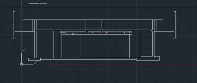
- Using Xline draw horizontal line
- Using offset command offst the line to top to adistance of 5850mm
- Offset the last offseted line to a distance of 300mm to the top
- Using xline draw vertical line
- Then offset to right at a distance of 10635mm
- Offset the last offsetted line to a distance of 3900
- Offset the last offsetted line to a distance of 5740
- Offset the last offsetted line to a distance of 5025
- Offset the left and right edges to a distance of 500mm
- Using trim command trim all the unwanted lines
STEP 3
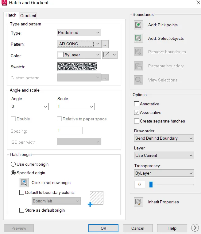
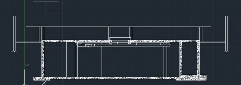
- Using the hatch command hatching is done
- Select the pattern here AR-CONC is selected
- Scale the pattern accordingly
- Then click the area or object to be hatched and then press enter
- Using properties panel can change the hatch type, colours , angle and can scale for the hatch
STEP 4
- Using MTEXT command all the text are made
- Using Dimlinear all the dimensions are marked
RESULT
--------------------------------------------------------------------------------------------------------------------------------------------