Creating Kitchen layout, Hatching of Architectural elements and sectional view of an Industrial Building in AutoCad
1.
Aim: To design Kitchen layout with proper dimension techniques to dimension the kitchen layout.
Introduction: To design Kitchen layout with proper dimension techniques and to hatch the kitchen layout by assuming some dimensions.
Procedure:
- First we need to set the dimension to mm which is given in the drawing.
- Then understand the drawing from which point to start the drawing.
- First take the Below counter plan and by calculating the inner dimesions, assume wall thickness and draw the outer lines.
- Then first you need to draw the outer portion of the drawing by using line command.
- After taking the dimensions, draw the plan by using line and offset command.
- You need to assume some dimensions which are not given in the drawing as shown in the given drawing.
-
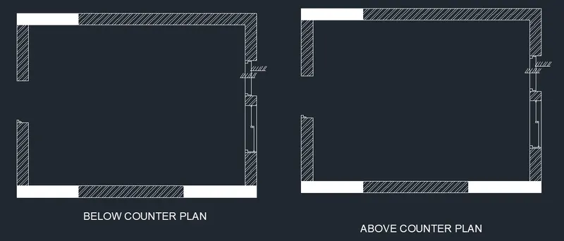
- Now take the given inner dimensions and draw one side at the below counter level plan.
- Then take the assumed door portion and trim the door portion in above and below counter plans.
- Now draw the door with assumed dimensions and insert the door in the trim portion as shown in the drawing.
- Then show the kitchen area and all the area which is given in the drawing.
- Also show the dimension to the inner part which is shown in the drawing as in the attached drawing.
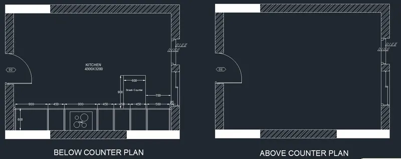
- Now take the given inner dimensions and draw other side at the below counter level plan.
- Now give the hatch to the outer wall as shown in the drawing.
- Then show the kitchen area and all the area which is given in the drawing.
- Also show the dimension to the inner part which is shown in the drawing as in the attached drawing.
-

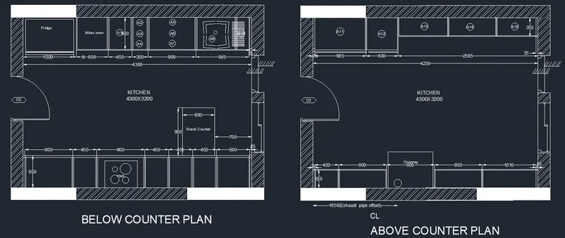
- By using the same procedure, draw the above counter plan.
- Then take the assumed door portion and trim the door portion in above counter plans.
- Now give the hatch to the outer wall as shown in the drawing.
- Finally mention all the dimensions which are given in the attachment and final drawing is attached in the result.
Result:
2. Aim: To create the elevation of plan created in challenge 7.
Introduction: To create the elevation of plan created in challenge 7 and to apply hatch to walls, doors, windows and other architectural elements.
Procedure:
- Before creating the drawing, we need to set the units by entering un command.
- And also set the limits in limmax command in x and y directions.
- Then we need to draw the elevation from the plan as in the given attachment.
- The elevation part is given in the attachment and we need to assume the dimensions.
- Or else wee can draw the elevation simply by using line command.
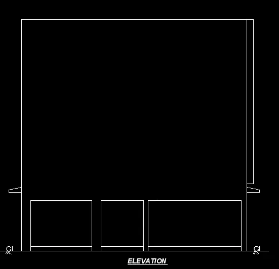
- By using the line command outer part of the elevation is drawn as shown in the below attachment.
-
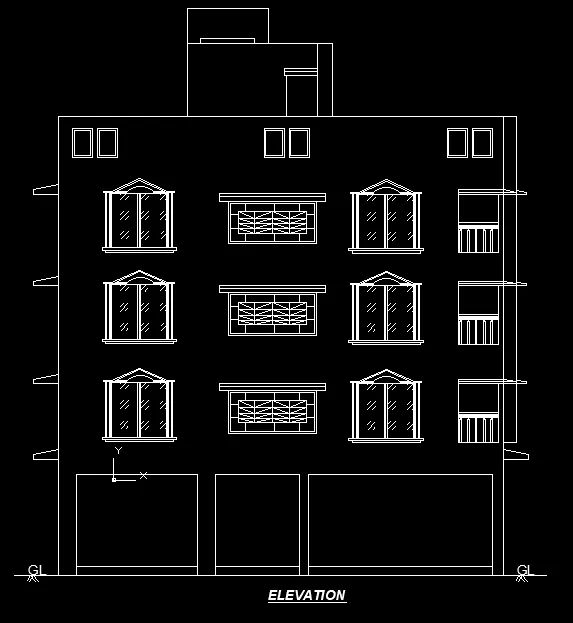
- Then after this there is a windows shown in the elevation which is shown in the plan.
- This windows are projected from the plan towards the elevation part.
- Then by using the line command we have to draw the window shape in the elevation.
- This window shape can be drawn by any model which can be shown neatly.
- And there is a lintel projected towards the wall for the windows wherever window is placed.
- Finally with all these drawig is ready and attached in the result.
Result:
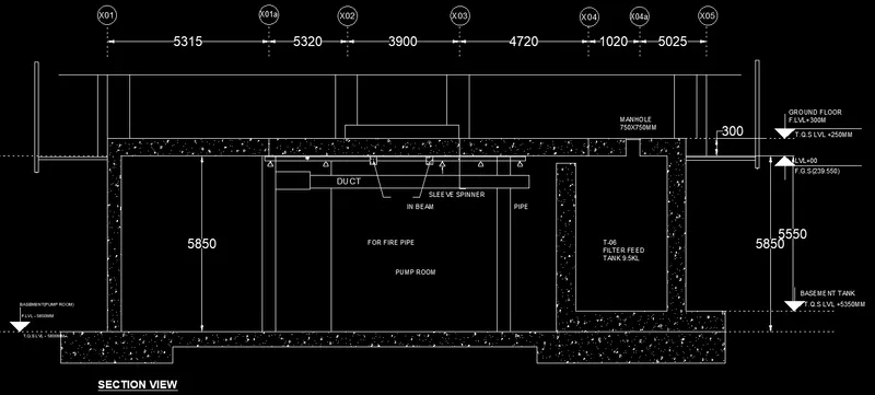
3. Aim: To create the section view of an industrial building.
Introduction: To create the section view of an industrial drawing as shown in the figure by providing hatches and dimensions.
Procedure:
- Before creating the drawing, we need to set the units by entering un command.
- And also set the limits in limmax command in x and y directions.
- Now there are the dimensions given in Millimeters to draw the sectional view.
- So we have to draw the outer part first by taking the dimensions wherever given.
- If the dimensions are not given then we can assume the dimension as per the construction standards.
- There is a pump room and duct area which is shown in the drawing.
- For this section, there is ground level to be mentioned in the drawing.
- And the drawing is attched below.
-
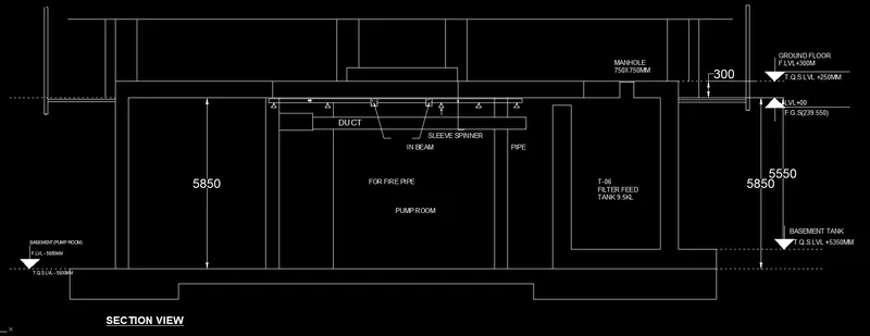
- Now after creating the portion, there is hatch portion shown in the drawing.
- This hatch portion represents the concrete slab level at the construction site.
- So we need to show the hatch wherever require with proper scale for clear view.
- This hatch portion should be a closed polyline with clear measurement.
- And dimensions to be shown wherever required and shown in the drawng.
- Finally the drawing is ready and attached in the result.
Result: