Creating Kitchen layout, Hatching of Architectural elements and sectional view of an Industrial Building in AutoCad
Ans 1:
Aim:
To create the layouts of the Kitchen and provide hatches pattern as shown. Also, use blocks wherever required. Provide appropriate dimensions in the plan. Assume the size of doors, appliances and others as per the standards.All dimensions are in mm.
Procedure:
1.Use line command to draw lines wherever required
2.Use rectangle command to draw room size (4734 * 3688)
3.The arch command is used to draw doors
4.Hatch command is used to show brickwork
5.Offset is used for wall thickness (230mm)
6.Use line type and load the dotted lines to show hidden object
7.Type text to text the given annotation
8.Use dimension command to show the dimension of the object
9.Leader command is used to name the dimension
10.Trim extra lines.
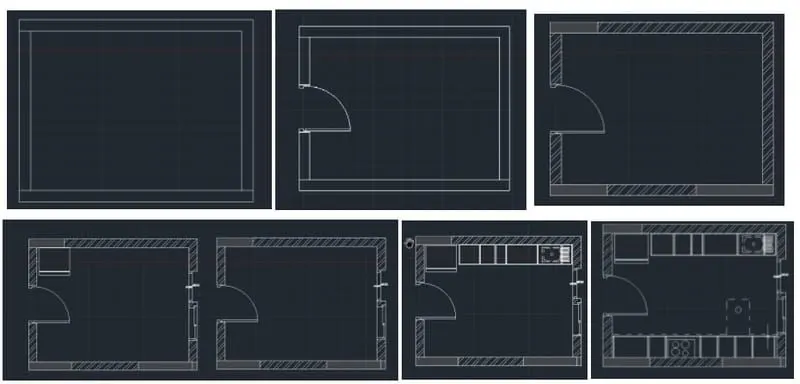
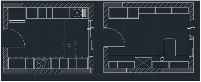
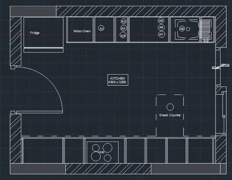
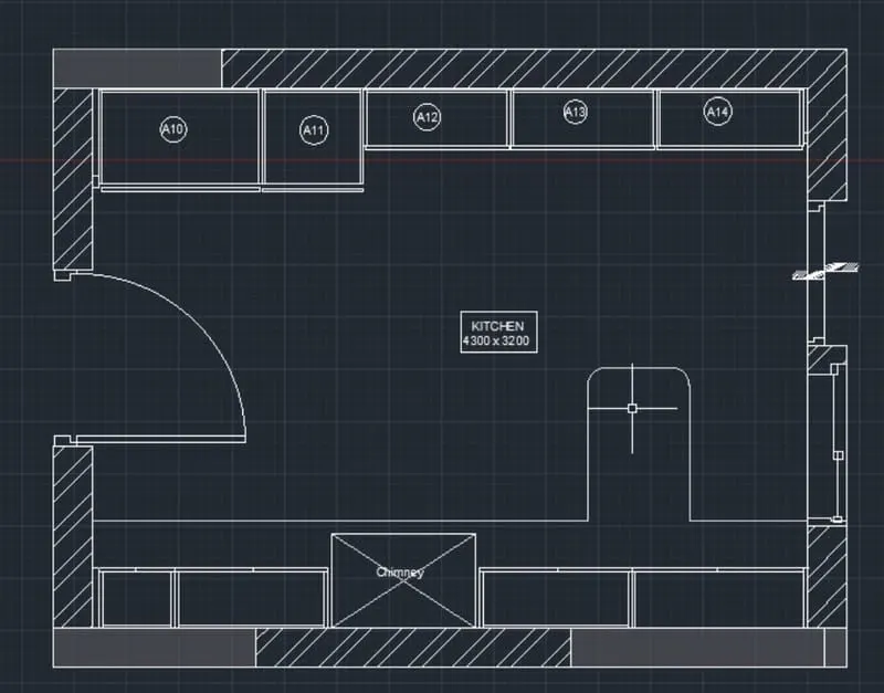
FINAL RESULT :
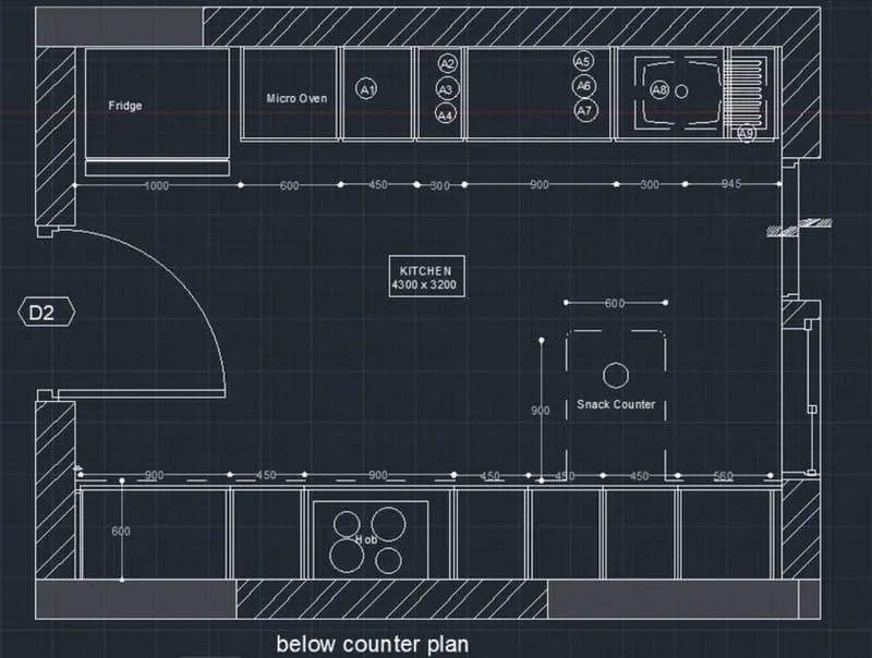
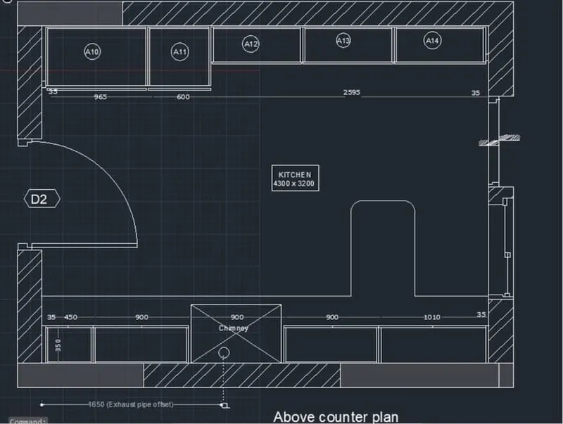
RESULT:
The given layout of the kitchen is created using AutoCAD.\
ANS 2:
AIM
To create the elevation of the given plan with hatch
PROCEDURE
1.Use line command to draw lines wherever required
2.Use rectangle command to draw room size
3.The arch command is used to draw doors
4.Hatch command is used to show brickwork
5.Offset is used for wall thickness
6.Use line type and load the dotted lines to show hidden object
7.Type text to text the given annotation
8.Use dimension command to show the dimension of the object
9.Leader command is used to name the dimension
10.Trim extra lines.
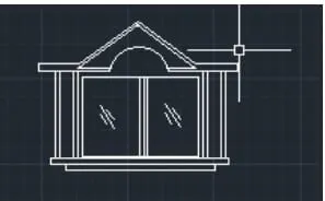
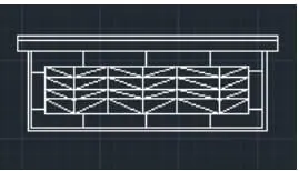
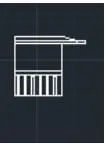
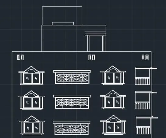
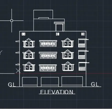
Final result:
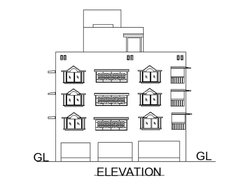
RESULT:
The given elevation is created using AutoCAD.
ANS 3:
AIM
To create section view of industrial building
PROCEDURE
1.Draw a line using the line command
2.In the ribbon bar > Hatch > AR.CONC
3.Draw rectangle where required
4.Command LT is used to draw dotted lines
5.Type c to draw a circle
6.Mt command is used to draft text
7.The dim command is used to show dimension.
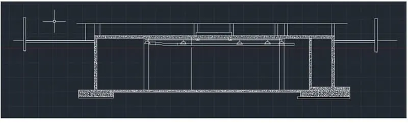
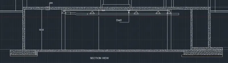
FINAL RESULT:
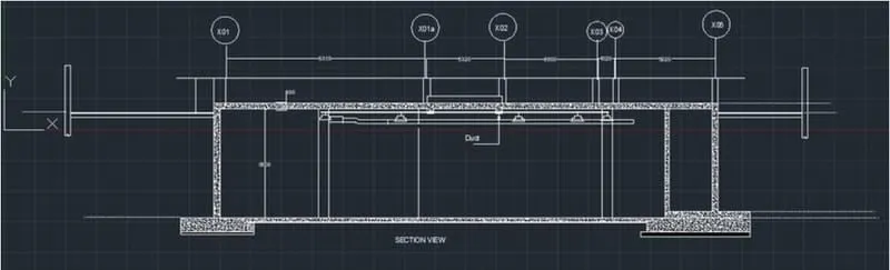
RESULT
The given industrial building section view is created using AutoCAD.