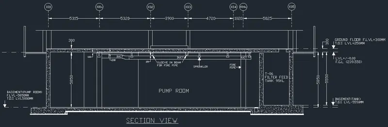
Creating Kitchen layout, Hatching of Architectural elements and sectional view of an Industrial Building in AutoCad
1) AIM: To create the layouts of the Kitchen and provide hatches pattern as shown.
PROCEDURE:
- Open Auto cad and open new drawing.
- Type ‘LIMITS’ in command bar and set the sheet limit as per drawing.
- Type ‘UNITS’ in command bar and set the unit type as Decimal and unit in millimeters set precision as required for drawing.
- Keep ortho on so that the lines move only in Right angles.
- Use line command and draw the outer wall and inner wall of the room.
- Next do the door using line and trim command.
- Use line command to show the frame and door length and thickness.
- Start with the below counter plan which includes stove sink and fridge etc.
- Trim off the lines carefully here trimming plays a major role.
- See in given drawing where the cutting is and where to be trimmed.
- After completing the drawing start with dimensioning.
- Select dotted in the dimension style and start the dimension.
- Before starting the dimension work go to prefix and select decimal as 0.
- Select the linear dimension and then select continue dimension.
- Now we have to only click of which we need dimension.
- It automatically starts from where we ended last.
- Then use Mtext and do all the naming where ever required.
- Make sure that the dimension and text size are clearly visible.
- Here we have 6 columns so place them as required.
- After the completion of drawing now start with the hatching.
- Type H in the command box and a dialogue box will appear as shown below
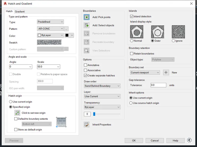
- First we have to select the boundaries so select Add pick points.
- Go to drawing and select the place where we need the hatch.
- Select the type of the hatch we need in pattern there are many pattern of different materials.
- Select the color angle and adjust the scale as required.
- If needed go for preview to see the hatch character.
RESULT:
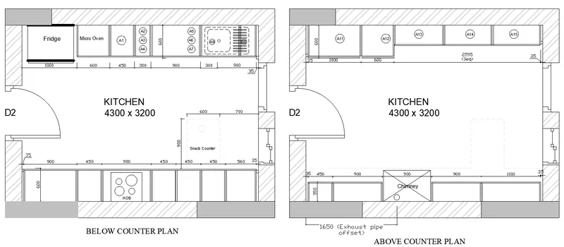
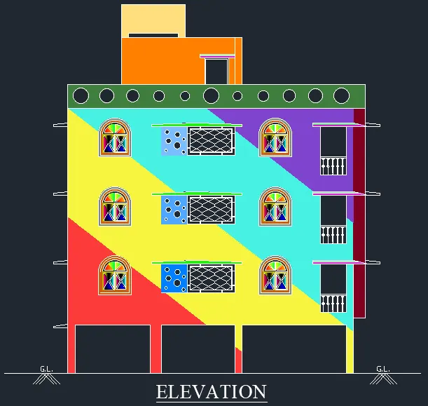
2) AIM: To create the elevation of the plan created in the Challenges 7 and apply proper hatch in the walls, doors, windows, and other architectural elements.
PROCEDURE:
- Open cad application in the pc and set all the limits required.
- Set the units as required for drawing. Set units in decimal and scale in Millimeters.
- Keep ortho on for easily drawing lines in right angles.
- Select construction line and draw the outer line of the wall.
- Make a base where drawing will be started.
- Draw the drawing as per the view.
- Imagine that you are standing in front of the building.
- Draw the Chajja and start with the front window and balcony.
- Show the front view of the window by doing the offset of the thickness of frame and material.
- First do all the window and balcony of full building which comes in the view.
- Do all the architectural drawing completely and next start with the hatch.
- Draw the diagonal lines in the front wall in the design we need.
- Type H in the command box and a dialogue box will appear as shown below
- First we have to select the boundaries so select Add pick points.
- Go to drawing and select the place where we need the hatch.
- Be careful while selecting the points in the window because the thickness is very less.
- Select the type of the hatch we need in pattern there are many pattern of different materials.
- Select the color angle and adjust the scale as required. Which matches the materials?
- If needed go for preview to see the hatch character.
- Here we can also use gradient method of hatching. Where we can add either two colors or only one color.
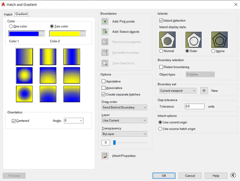
- Here we can select the type of gradient color method and required color also.
- Here we can also select the type of orientation of gradient there are several types.
- We can also change the gradient angles.
- There are also many types to select the area for hatching in Islands.
- There are many methods and uses in this hatching command.
- Once the hatching is done we can also edit it and change material, type, angle, scale anything.
- After all the hatching is done save the drawing.
- Here we have to select the scale in such a way that it is clearly visible.
RESULT:
3) AIM: To create the section view of an industrial building as shown in Figure.
PROCEDURE:
- Open Auto cad and open new drawing.
- Type ‘LIMITS’ in command bar and set the sheet limit as per drawing.
- Type ‘UNITS’ in command bar and set the unit type as Decimal and unit in millimeters set precision as required for drawing.
- Keep ortho on so that the lines move only in Right angles.
- Use line command and draw the centerline using given dimension.
- Trim off the lines carefully here trimming plays a major role.
- See in given drawing where the cutting is and where to be trimmed.
- Use offset to show the thickness of given drawing for detailing.
- DO all the offset so that there are no error.
- After completing the drawing start with dimensioning.
- Select dotted in the dimension style and start the dimension.
- Before starting the dimension work go to prefix and select decimal as 0.
- Select the linear dimension and then select continue dimension.
- Now we have to only click of which we need dimension.
- It automatically starts from where we ended last.
- Then use Mtext and do all the naming where ever required.
- Make sure that the dimension and text size are clearly visible.
- Start with the hatching where ever required with respect to materials.
- Do the hatching as mentioned in above procedures.
- Make sure the hatch is clearly visible and are not fully conjusted.
RESULT: