Creating Kitchen layout, Hatching of Architectural elements and sectional view of an Industrial Building in AutoCad
1Q]
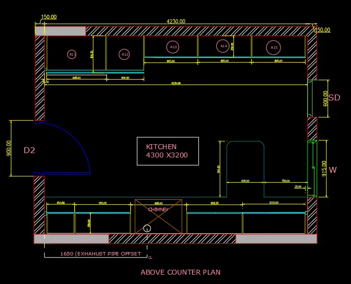
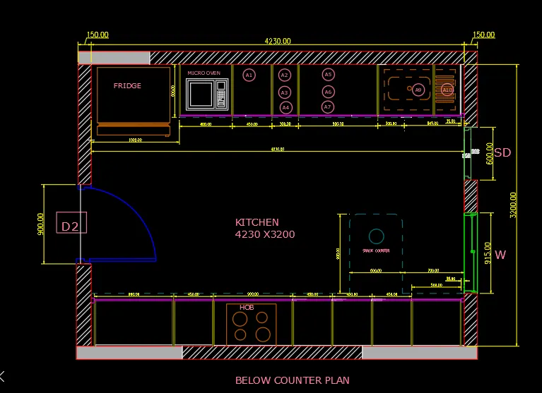
AIM: -
Create Layouts of Kitchen
Provide Hatches pattern as shown.
Use blocks wherever required.
Provide appropriate Dimensions and Annotation.
PROCEDURE: -
Start the AutoCAD with units as Metric
Set the Units to Decimals
Type XREF
Open External References Tab
Select “Attach Dwg “ option
Choose the Challenge 6 Kitchen.dwg file
Open the file as External reference.
Drawing file acts as a External reference. Here we can’t edit the layers.
To edit the Layers and work on it,
Type XREF
Right click on the Attached file that is Challenge 6 Kitchen dwg file.
Select Bind option
Bind Tab opens, select bind option and press OK
Now the External Reference file converts to block.
Type EXPLODE
Select the block
The block turns to an object
Now we can work on the drawing.
Before we start the drawing create Blocks in the respective Layers.
Select Layer as WINDOWS
Type “B”
Open Block Definition box
Name: Challenge_10_window
Base point: Pick point of window
Objects: Select window on screen
Click on Convert to block
Behaviour: Scale uniformly
Allow Exploding
Press OK.
Type “B”
Open Block Definition box
Name: Challenge_10_slide door
Base point: Pick point
Objects: Select slide door on screen
Click on Convert to block
Behaviour: Scale uniformly
Allow Exploding
Press OK.
Select layer as DOOR
Type “B”
Open Block Definition box
Name: Challenge_10_door
Base point: Pick point of door
Objects: Select window on screen
Click on Convert to block
Behaviour: Scale uniformly
Allow Exploding
Press OK.
Type ATTDEF
Open ATTRIBUTE DEFINITION box
Mode: Preset
Lock Position
Attribute:
Tag: A1
Prompt: what is the value?
Default: A1
Insertion Point: Specify on Screen
Text Settings:
Justification: left
Text height: 40
Press OK.
Draw Circle
Place the Attribute A1 at the centre of the circle.
Type “B”
Open Block Definition box
Name: Challenge_10_A1
Base point: Pick point of door
Objects: Select window on screen
Click on Convert to block
Behaviour: Scale uniformly
Allow Exploding
Press OK.
Type “I”
Open current drawing in Insert Box
Here you see the list of Blocks created.
Select the window block
Insertion Point specify on screen
Scale : 1
Rotation angle: 0
Press OK.
Locate the window at the respective positions.
Type “I”
Open current drawing in Insert Box
Here you see the list of Blocks created.
Select the slide Door block
Insertion Point specify on screen
Scale : 1
Rotation angle: 0
Press OK.
Locate the Slide Door at the respective positions.
Type “I”
Open current drawing in Insert Box
Here you see the list of Blocks created.
Select the Door block
Insertion Point specify on screen
Scale : 1
Rotation angle: 0
Press OK.
Locate the Door at the respective positions.
Type “I”
Open current drawing in Insert Box
Here you see the list of Blocks created.
Select the A1 block
Insertion Point specify on screen
Scale : 1
Rotation angle: 0
Press OK.
Locate the A1 bock at the respective positions.
Type ATTEDIT
Select the Block Reference
Edit Attributes box opens
Change the value to A2
Press OK.
Locate this A2 block wherever required.
Repeat this till A15 value and locate these wherever required as per the figure given.
Type “ADC”
Open the Design Centre Box
Go to AutoDesk > AutoCAD 2020 > Sample > en-us > Design Centre > kitchens dwg > blocks
Drag the Micro oven Block to the screen
Scale the block and place it at the appropriate position.
Type “H”
Open Hatch and gradient Settings box
Type: predefined
Pattern: ANSI132
Boundaries: Add pick points
Scale: 10
Island Detection: outer
Options: Click on Associative
Click on Create Separate hatches.
Check Preview
If everything is OK
Press OK
Type “H”
Click on the object wherever the ANSI132 hatch is to be done.
Press Enter.
Type LAYER
Set the Dimensions as Current Layer
Provide Dimensions to each cabin and wall thickness
Set the TEXT as Current Layer
Provide Text as per given in the figure.
RESULT: -
We creatd Layouts of Kitchen by providing Hatches pattern as shown and by using blocks wherever required.
Provided appropriate Dimensions and Annotation.
2Q]
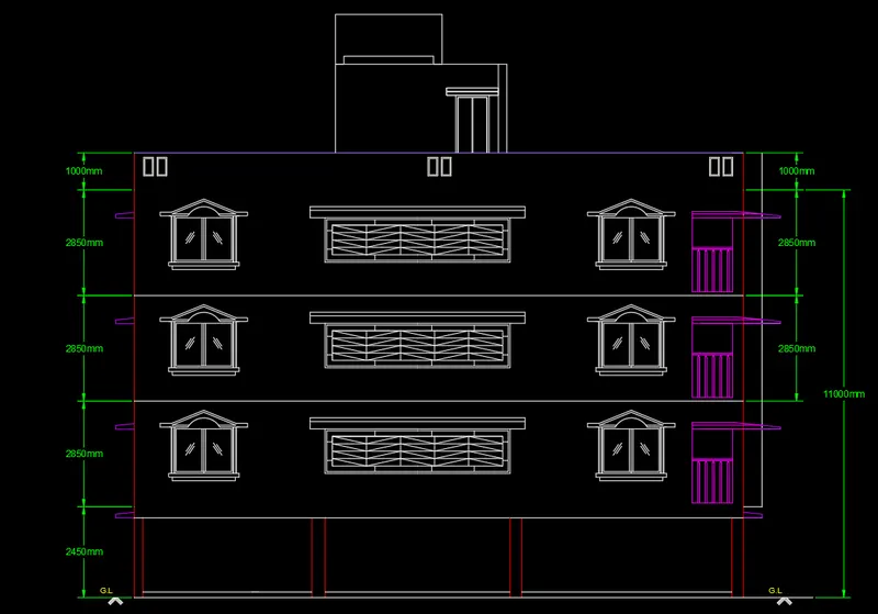
AIM: -
Create the Elevation for the plan created in Challenge 7.
Apply proper Hatch in the walls, Doors, windows and other Architectural elements.
PROCEDURE: -
Start the AutoCAD with units as Metric
Set the Units to Decimals
Type XREF
Open External References Tab
Select “Attach Dwg “ option
Choose the Challenge 7 Floor Plan.dwg file
Open the file as External reference.
Drawing file acts as an External reference. Here we can’t edit the layers.
To edit the Layers and work on it,
Type XREF
Right click on the Attached file that is Challenge 6 Kitchen dwg file.
Select Bind option
Bind Tab opens, select bind option and press OK
Now the External Reference file converts to block.
Type EXPLODE
Select the block
The block turns to an object
Now we can work on the drawing.
Type XLINE
Select Hor option and project column position and windows location to Elevation.
Measure the Elevation Length from the plan.
Refer plan details for thickness of wall.
Trim the edges using TRIM command
Type “L”
Select Line tool and Provide to the Elevation.
From G.L to 1st floor provide height of 2450 units
From 1st floor to 2nd floor provide height of 2850 units.
From 2nd floor to 3rd floor provide height of 2850 units.
Provide parapet wall height of 1000 units on above 3rd Floor.
Draw Balcony at 1st floor.
Copy and paste for 2nd floor and 3rd floor.
Provide window shades at each floor.
Draw Staircase room
Draw Door for the staircase room
Draw O.H.T above the staircase room as given in the figure.
Type LAYER
Select Create new layer
Name: Hatch
HATCH WINDOWS
Hatch for window BOTTOM CHAJJA
Type “H”
Open Hatch and gradient Settings box
Type: predefined
Pattern: ANGLE
Boundaries: Add pick points
Scale: 15
Island Detection: outer
Options: Click on Associative
Click on Create Separate hatches.
Check Preview
If everything is OK
Press OK
Hatch for window SIDE PANELS
Type “H"
Open Hatch and gradient Settings box
Type: predefined
Pattern: AR-PARQ1
Boundaries: Add pick points
Scale: 0.1
Island Detection: outer
Options: Click on Associative
Click on Create Separate hatches.
Check Preview
If everything is OK
Press OK
Hatch for window PANELS
Type “H”
Open Hatch and gradient Settings box
Type: predefined
Pattern: NET3
Boundaries: Add pick points
Scale: 40
Island Detection: outer
Options: Click on Associative
Click on Create Separate hatches.
Check Preview
If everything is OK
Press OK
Hatch for window TOP CHAJJA OUTER
Type “H”
Open Hatch and gradient Settings box
Type: predefined
Pattern: ESCHER
Boundaries: Add pick points
Scale: 5
Island Detection: outer
Options: Click on Associative
Click on Create Separate hatches.
Check Preview
If everything is OK
Press OK
Hatch for window TOP CHAJJA INNER
Type “H”
Open Hatch and gradient Settings box
Type: predefined
Pattern: HOUND
Boundaries: Add pick points
Scale: 5
Island Detection: outer
Options: Click on Associative
Click on Create Separate hatches.
Check Preview
If everything is OK
Press OK
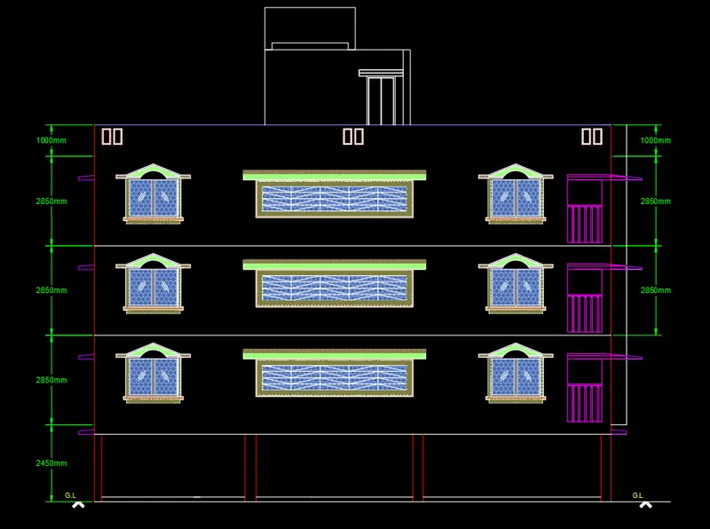
Apply HATCH to COLUMNS.
Type “H”
Open Hatch and gradient Settings box
Type: predefined
Pattern: AR-CONC
Boundaries: Add pick points
Scale: 1
Island Detection: outer
Options: Click on Associative
Click on Create Separate hatches.
Layer: Hatch
Check Preview
If everything is OK
Press OK
Apply HATCH to PARKING FLOOR.
Type “H”
Open Hatch and gradient Settings box
Type: predefined
Pattern: AR-HBONE
Boundaries: Add pick points
Scale: 0.5
Island Detection: outer
Options: Click on Associative
Click on Create Separate hatches.
Layer: Hatch
Check Preview
If everything is OK
Press OK
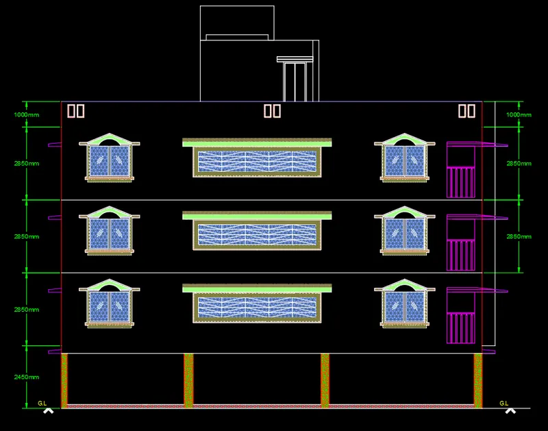
Apply HATCH to WALLS OF 1ST, 2ND AND 3RD FLOOR.
Type “H”
Open Hatch and gradient Settings box
Type: predefined
Pattern: AR-B816
Boundaries: Add pick points
Scale: 1
Island Detection: outer
Specify origin
Options: Click on Associative
Click on Create Separate hatches.
Layer: Hatch
Check Preview
If everything is OK
Press OK
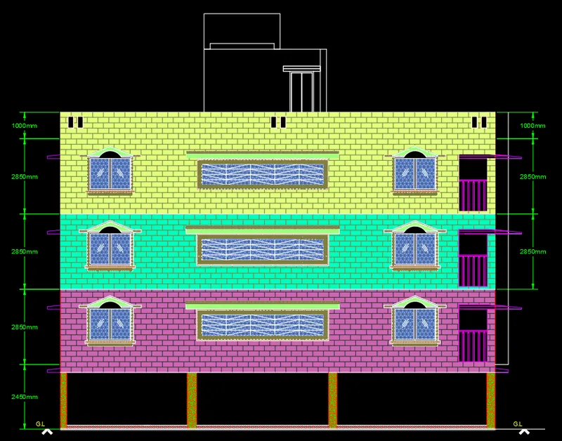
Apply HATCH to STAIRCASE ROOM WALL
Type “H”
Open Hatch and gradient Settings box
Type: predefined
Pattern: HOUND
Boundaries: Add pick points
Scale: 15
Island Detection: outer
Specify origin
Options: Click on Associative
Click on Create Separate hatches.
Layer: Hatch
Check Preview
If everything is OK
Press OK
Apply HATCH to STAIRCASE ROOM DOOR
Type “H”
Open Hatch and gradient Settings box
Type: predefined
Pattern: EARTH
Boundaries: Add pick points
Scale: 10
Island Detection: outer
Specify origin
Options: Click on Associative
Click on Create Separate hatches.
Layer: Hatch
Check Preview
If everything is OK
Press OK
Apply HATCH to O.H.T
Type “H”
Open Hatch and gradient Settings box
Type: predefined
Pattern: HONEY
Boundaries: Add pick points
Scale: 15
Island Detection: outer
Specify origin
Options: Click on Associative
Click on Create Separate hatches.
Layer: Hatch
Check Preview
If everything is OK
Press OK
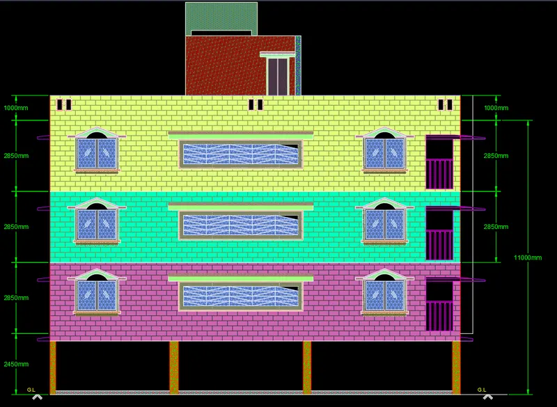
Set the Dimensions as Current Layer
Provide Dimensions
RESULT: -
We created Elevation from Floor Plan challenge 7 and applied HATCH to each Architectutal elements.
3Q]
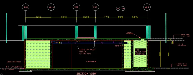
AIM: -
Create the Section View of Industrial Building.
Provide appropriate dimensions and hatches.
Provide Annotations.
PROCEDURE: -
Start the AutoCAD with units as Metric
Set the Units to Decimals
Type XLINE
Select Hor option and draw Horizontal line on screen.
Select Vert option and draw Vertical line on screen.
Select Horizontal line and provide OFFSET with offset distance as 5850mm
Select horizontal line and provide OFFSET with offset distance as 300mm
Select vertical line and provide OFFSET with offset distance as 300mm
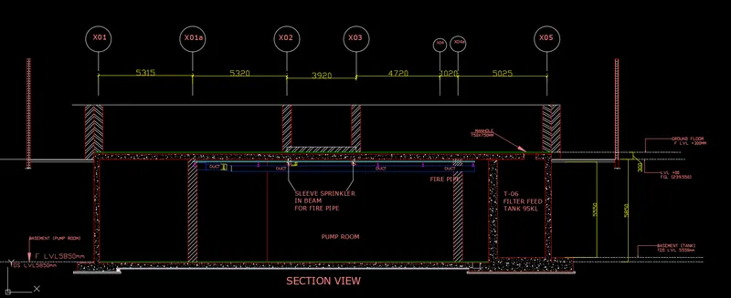
Column is formed with height 5850 units with slab thickness as 300 units.
Mark the centre line of this column using centre line command
Label this centreline as “X01”
Provide OFFSET to this centreline at a distance of 5315 units.
Draw column at this position.
Column is formed with height 5850 units with slab thickness as 300 units.
Label this centreline as “X01a”
Provide OFFSET to this centreline at a distance of 5320 units.
Label this centreline as “X02”
Provide OFFSET on both sides of this centreline.
Draw column on above the slab
From “X02” centreline, provide vertical offset at distance of 3900 units
Draw column on above the slab.
Draw beam below the slab.
Mark this centreline as “X03”
Draw column on above the slab.
Draw beam below the slab.
From “X03” centreline, provide vertical offset at distance of 3900 units
Label this line as “X04”
From “X03” centreline, provide vertical offset at distance of 1020 units
Label it as “X04a”
At X04a draw a column below the slab.
From “X04a” centreline, provide vertical offset at distance of 5025 units
Name it as “X05”
In between X04a and X05 :
Draw walls to Filter Feed Tank as given in figure.
Draw manhole of size 750 x 750 units. to this tank
Now trim all the unnecessary lines.
Provide Footing to the Column at “X01” and to the Feed Tank as shown in figure.
Type LAYER
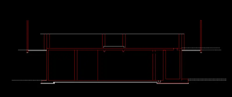
Select Create new layer: OUTER LINES.
Set colour to this layer.
Type LAYER
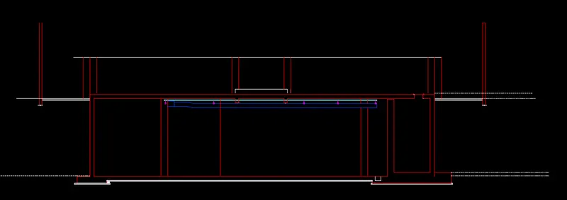
Select Create new layer: sprinkler.
Set colour to this layer.
Below the slab draw Sprinkler from X01a to X04a passing through the beams
Type LAYER
Select Create new layer: DUCT.
Set colour to this layer.
Draw the duct of thickness 200 units below the beams from X01a to X04a
Type LAYER
Select Create new layer: CONNECTIONS.
Set colour to this layer.
Provide links to sprinkler and Duct.
HATCH for Columns connecting slab,and footing.
Type “H”
Open Hatch and gradient Settings box
Type: predefined
Pattern: AR-CONC
Boundaries: Add pick points
Scale: 2
Island Detection: outer
Specify origin
Options: Click on Associative
Click on Create Separate hatches.
Layer: Hatch
Check Preview
If everything is OK
Press OK
HATCH for Columns above slab
Type “H”
Open Hatch and gradient Settings box
Type: predefined
Pattern: ANSI132
Boundaries: Add pick points
Scale: 15
Island Detection: outer
Specify origin
Options: Click on Associative
Click on Create Separate hatches.
Layer: Hatch
Check Preview
If everything is OK
Press OK
Select ANNONTATE in Ribbon
Under TEXT dialogue box
Choose Multiline Text tool
Using MTEXT label the details
Select command: ‘_STYLE
Create new style with Font name - Arial and Font Style – Regular
Set current.
Type LAYER
Name: Text
Set colour to the layer
Set current.
Type all the TEXTS given in the Figure
Select LEADERS PALETTE
Choose MULTILEADER STYLE MANAGER
Create new style
Modify the Leader format, Leader structure, Content
And Set current.
Use LEADERS command wherever required.
Select LAYER properties dialogue box
Create New Layers
Select different COLOUR to each layer created.
Set the Dimensions as Current Layer
Select ANNONTATE in Ribbon
Under DIMENSION dialogue box
Select DIMLINEAR command to mark column dimensions, and then
Select DIMCONTINUE command to mark the distances between partitions.
Select Centrelines palette
Choose CENTRELINE command to draw centreline wherever required.
Provide Dimensions to all the objects.
RESULT: -
We create the Section View of Industrial Building.
We provided appropriate dimensions, Annotations and hatches.