Creating Kitchen layout, Hatching of Architectural elements and sectional view of an Industrial Building in AutoCad
1-Create the layouts of the Kitchen and provide hatches pattern as shown. Also, use blocks wherever required. Provide appropriate dimensions in the plan. Assume the size of doors, appliances and others as per the standards.
AIM:
To create kitchen layout and details by using AutoCAD with the help of given figure.
INTRODUCTION:
The kitchen layout is created in AutoCAD by using the tools like Draw, Modify, Annotation, Layer, Block and Properties. All the dimensions are in MM. The procedure of kitchen layout is explained in detail with figure and the final result is given.
PROCEDURE:
STEP 1) SELECTION OF MODAL FOR DRAWING
- Open AutoCAD
- STARTUP enter for new drawing
- Enter new value for startup 1 enter
- Create new file (a dialog box open START FROM SCRATCH)
- Select default setting as METRIC click on OK
- UN enter for unit setting
- Select DECIMAL, precision 0 in type
- Insertion scale select MILIMETER Click OK
- LIM enter for set limit
- Specify lower left corner 0,0 enter
- Specify upper right corner 10000,10000 enter
- Z enter for zoom
- Zoom for select ALL or A enter
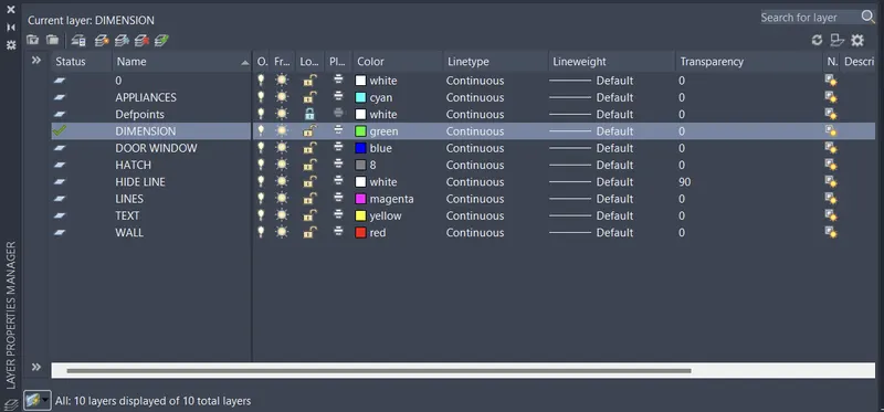
STEP 2) ASSIGNED LAYER PROPERTY
- RIBBON > LAYER PROPERTIES
- CREATE NEW LAYER > RENAME LAYER > WALL, DOOR, TEXT, HATCH, APPLIANCES, DIMENSION etc.
- Change colour for different layer
- Change transparency of HIDE LINE layer as 90
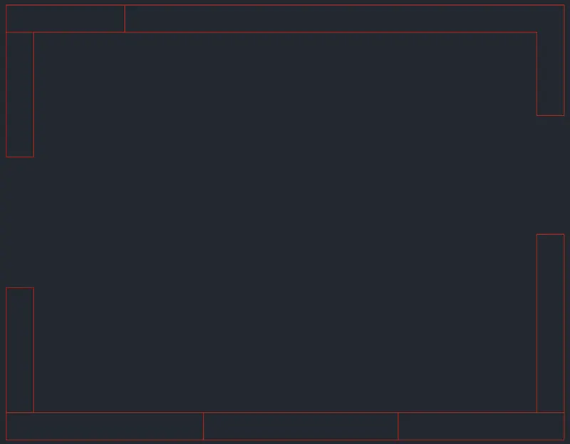
1)Walls
- Set layer as a Wall
- REC enter for Rectangle
- Specify first corner point 0,0
- Specify other corner point @4230,3200
- O enter for Offset
- Specify offset distance 230 enter
- Select object to offset click on rectangle
- Specify point on side to offset move cursor outside of the rectangle Esc
- X enter for Explode
- Select objects click on both rectangles then press enter
- Trim, erase and offset command used to provide opening for door and window
- Select particular line use grip to stretch and move wherever required
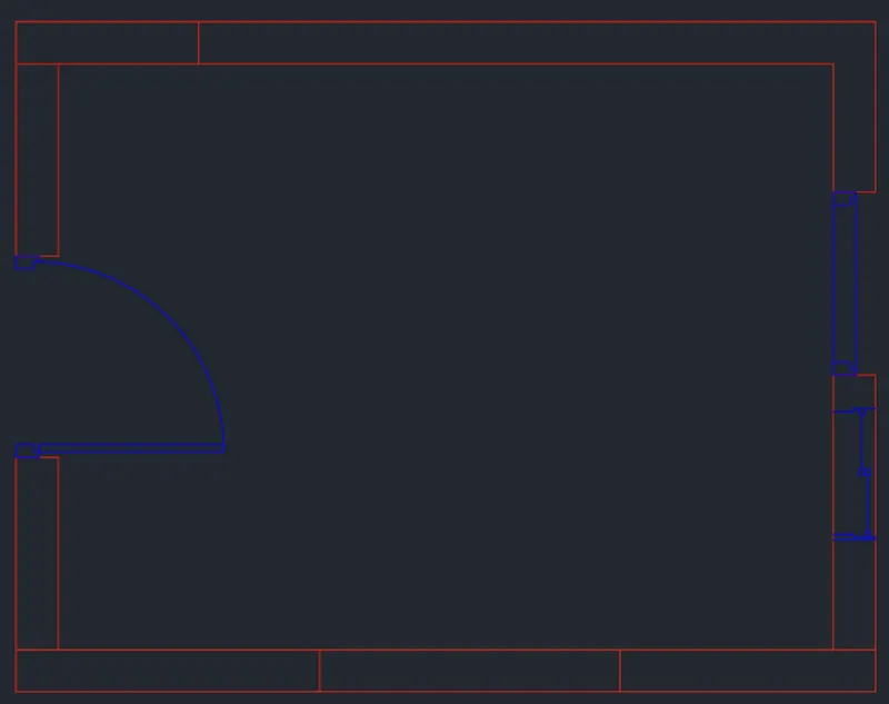
2)Door’s window
- Change layer as Door Window and Ventilation
- create door window then convert into block
- Doors, Windows insert as a Blocks
- Then select to place at required position or location
- Make a copy of this plan for above counter plan
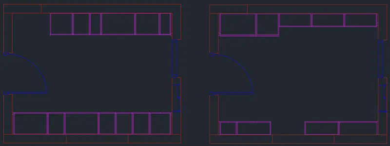
3)Lines
- Select layer as Lines from layer property and created lines as per given dimension in drawing for below and above counter plan with the help of Line, copy, offset, mirror, trim and extend command
- Select layer as Hide Line form layer property and create snack counter table, counter table
- Select these hide line for below counter plan and change the properties of linetype ISO dash with scale 1
4)Hatch
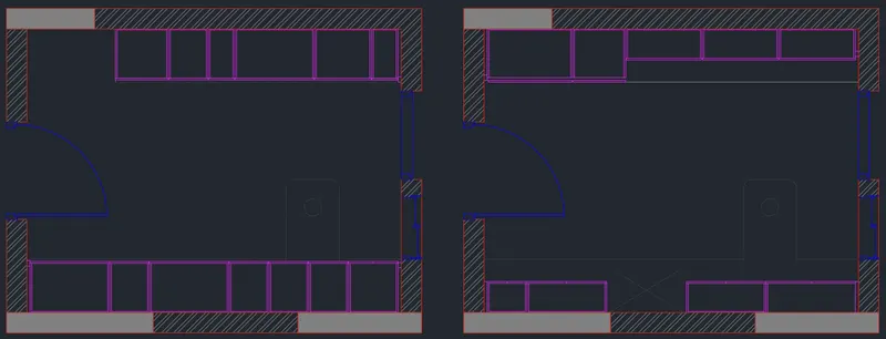
- Set layer as hatch from layer property
- Hatching provides as reference taken from given drawing
- pattern solid and ANSI32
5) Appliances
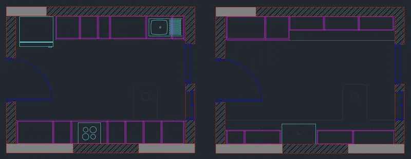
- Ribbon > View > Palettes > Design Center
- Select fridge and sink copy them to the drawing and to be scale for the positions and size
- Hob and chimney created by the help of line and circle command
6)Text
- Set layer as Text
- ST enter for STYLE TEXT dialog box
- Select the font name as ARIAL
- and change the text height as 80
- Apply > Set Current > Close
- MT(MTEXT) enter multiline text
- Specify the name of objects
- Edit the text as required size
7)Dimension
- Set layer as Dimension
- D enter for Dimension Style Manager
- Change extension line suppress check mark on Ext line 1 and Ext line 2 from Lines Tab
- Change the arrowheads first & second Dot Small from Symbols and Arrow Tab
- Text placement vertical & horizontal select centred from Text Tab
- Use over all scale of 30 from Fit Tab
RESULT:
After following above step by step procedure got result as shown below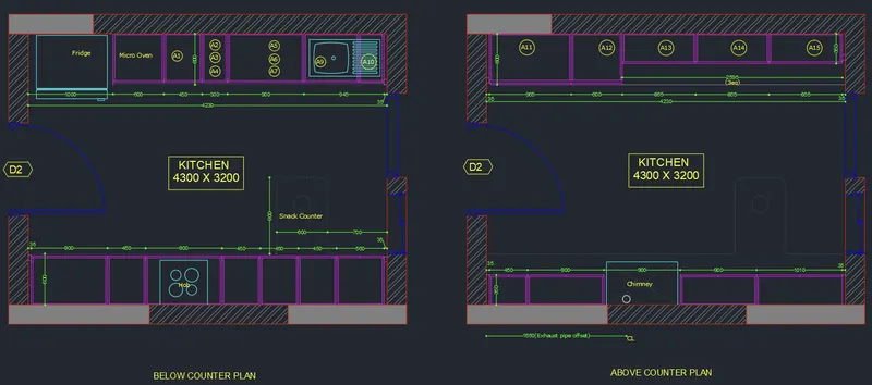
2. Create the elevation of the plan created in the Challenges 7 and apply proper hatch in the walls, doors, windows, and other architectural elements. Refer to the dimensions in Plans and sections in Challenges 7.
Refer to the elevation that needed to be created.
AIM:
To draw the elevation of the plan created in challenges 7 and apply proper hatch in the wall, doors, window, and other architectural elements in AutoCAD
INTRODUCTION:
The elevation is created in AutoCAD by using tool like Draw, Modify, Annotation, Layer and Properties. Text, dimension and hatch are provided. The procedure of kitchen layout is explained in detail with figure and the final result is given.
PROCEDURE:
STEP 1) SELECTION OF MODAL FOR DRAWING
- Open AutoCAD
- STARTUP enter for new drawing
- Enter new value for startup 1 enter
- Create new file (a dialog box open START FROM SCRATCH)
- Select default setting as METRIC click on OK
- UN enter for unit setting
- Select DECIMAL, precision 0 in type
- Insertion scale select MILIMETER Click OK
- LIM enter for set limit
- Specify lower left corner 0,0 enter
- Specify upper right corner 20000,20000 enter
- Z enter for zoom
- Zoom for select ALL or A enter
STEP 2) ATTACHING DRAWING
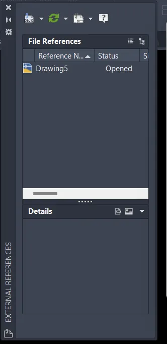
- Enter XREF for external reference command
- Click on icon to attach drawing
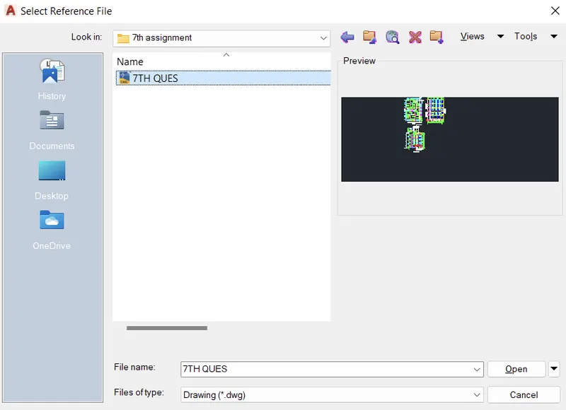
- Select reference file from dialog box
- Browse and open 7th week of challenge
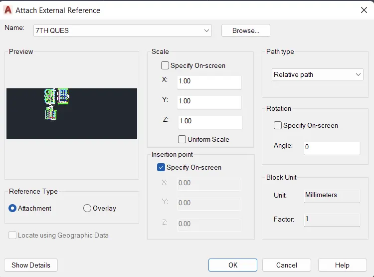
- Attach external reference dialog box open then click on ok
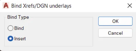
- Now again, enter command XREF for attached drawing to bind>insert
STEP3) CRETAE DRAWING
- Select exist layer as wall
- With the help of XL line command create projection of the floor plan
- Create horizontal line for level of floor
- Trim and erase to remove unwanted line
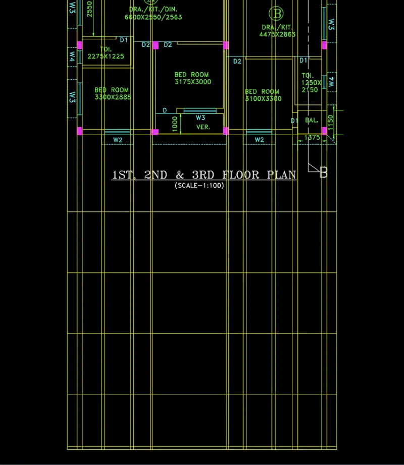
STEP4) CREATE WINDOW
- With the help of line command to create window
- First of all, create window frame by the offset command at 50 distances
- Then create window panel
- The create pillars for chajja by the help of offset
- Create incline line then mirror it
- Create arc for chajja
- After that trim and erase to remove all unwanted line
- Finally get the shape of window

STEP 5) CREATE VARANDA GRILL
- Create grill in the projection lines of between columns
- Line command to help the creation of the design like given in drawing
- Offset and trim command used to create the grill
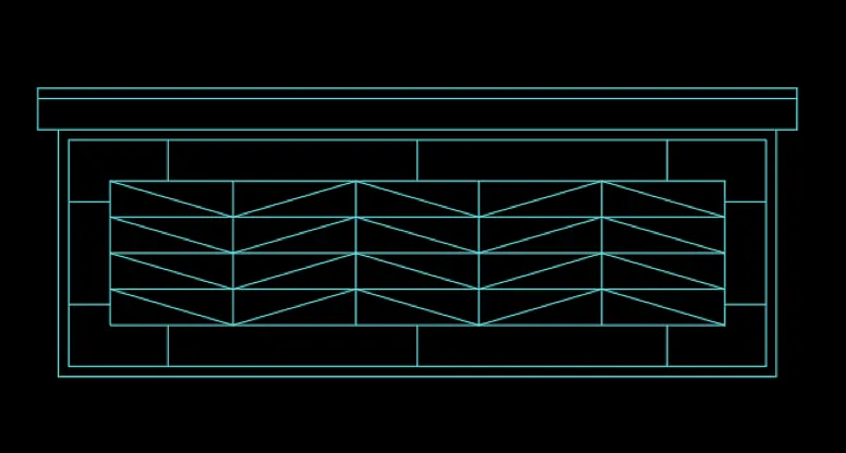
STEP 6) CREATE ELEVATION
- Choose layer according to elements
- Copy window and grill to paste each level
- Create chajja and other design which is given in drawing
- Create balcony railing and chajja
- Create mummty slab level
- Create overhead tank
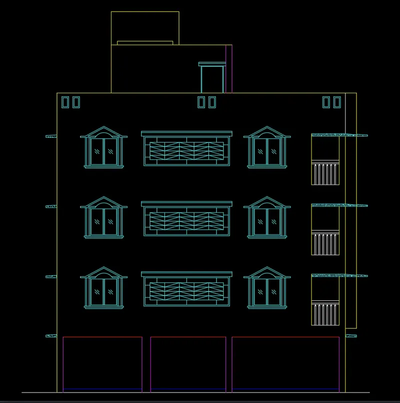
STEP 7) HATCHING
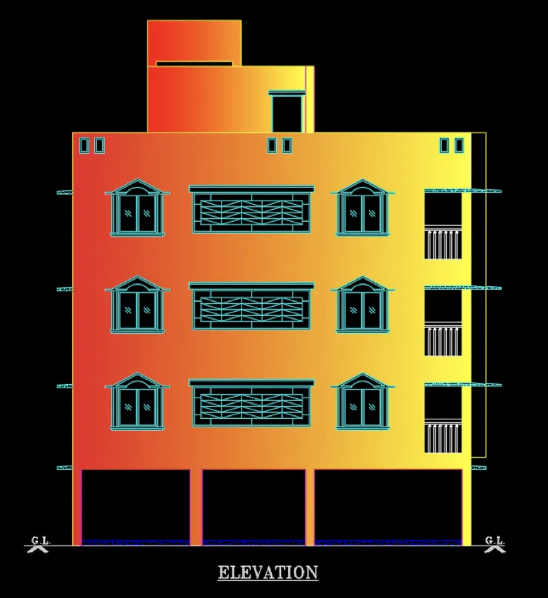
- H enter for hatch
- Select gradient linear
- Change colure
- Pick internal point
RESULT:
After following above step by step procedure got result as shown below
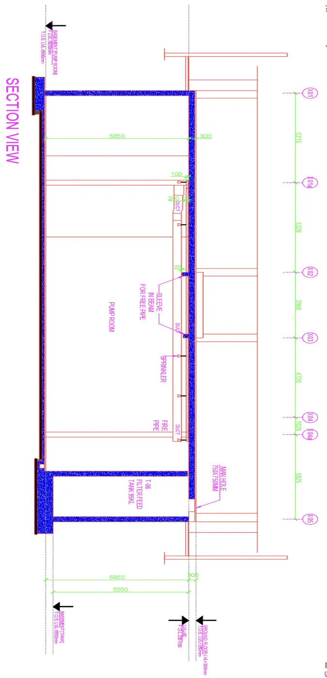
3. Create the section view of an industrial building as shown in Figure. Provide appropriate hatches and dimensions wherever required. Also, provide annotations to the drawing.
AIM:
To draw the section view of an industrial building as shown in figure.
INTRODUCTION:
The section is created in AutoCAD by using tool like Draw, Modify, Annotation, Layer and Properties. Text, dimension and hatch are provided. The procedure of kitchen layout is explained in detail with figure and the final result is given.
PROCEDURE:
STEP 1) SELECTION OF MODAL FOR DRAWING
- Open AutoCAD
- STARTUP enter for new drawing
- Enter new value for startup 1 enter
- Create new file (a dialog box open START FROM SCRATCH)
- Select default setting as METRIC click on OK
- UN enter for unit setting
- Select DECIMAL, precision 0 in type
- Insertion scale select MILIMETER Click OK
- LIM enter for set limit
- Specify lower left corner 0,0 enter
- Specify upper right corner 20000,20000 enter
- Z enter for zoom
- Zoom for select ALL or A enter
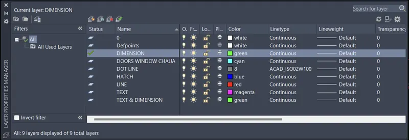
STEP 2) ASSIGNED LAYER PROPERTY
- Create some new layer for the section
STEP 3) CREATE LINES FOR SECTION
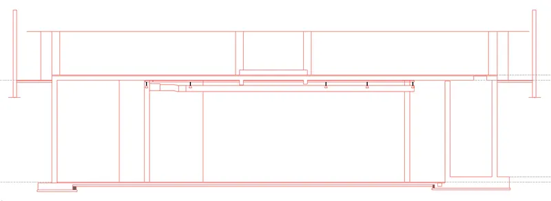
- XL line command to create horizontal and vertical line
- Trim over intersection point
- Take offset as given distance
- Create as per given drawing
STEP 4) HATCH
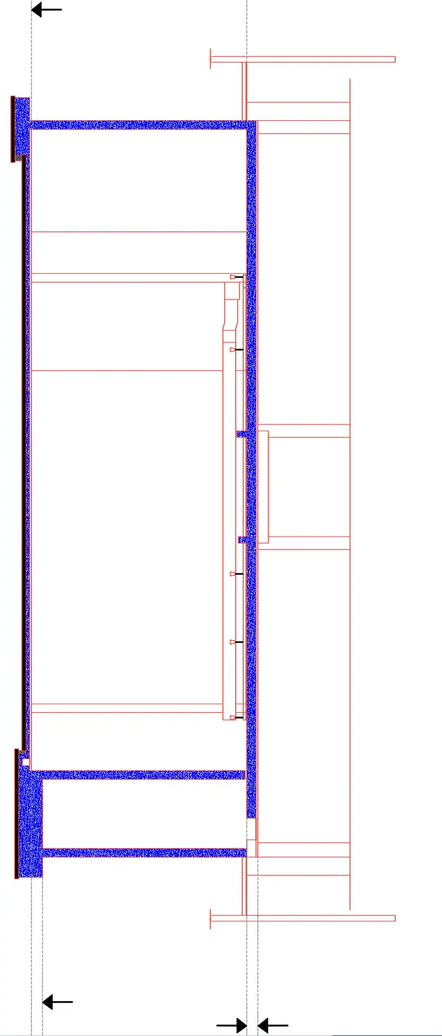
- H enter for hatch
- Fill the wall with pattern of AR-CONC and set scale
- Bottom fill with solid pattern
STEP5) TEXT AND DIMENSION
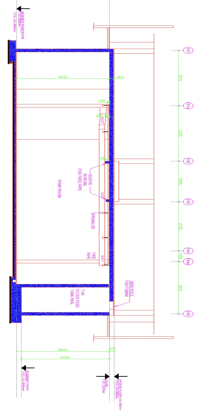
- Create multileader for showing the direction of element
- And type the of element
- Multiline text used for other text
- Change font and style of text
- Set layer after provide text
- DIMLIN enter of showing distance
RESULT:
After following above step by step procedure got result as shown below